Review of the Air Force Academy
No.1 (36)/2018
REAL-EMULATED-SIMULATED INTEGRATED ENVIRONMENT FOR TESTING COMPUTER NETWORKS
Daniel-Mihai BENGA, Marian ALEXANDRU Transilvania University, Brasov, Romania (
[email protected],
[email protected]) DOI: 10.19062/1842-9238.2018.16.1.6 Abstract: The goal of this paper is to identify the various problems that may arise within a computer network and monitor them by testing various scenarios encountered in everyday life. The network was configured with the GNS3 emulator simultaneously with SNMP and OSPF protocols in order to highlight the shortest way of data packets from source to destination. The results of the different scenarios tested can be interpreted using the MIB Browser (iReasoning), the SNMP protocol, and the CACTI tool so that the results of the different scenarios in the network could be observed. Keywords: GNS3, OSPF, SNMP, CACTI, iReasoning
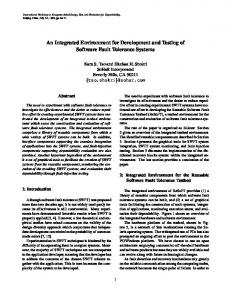
1. INTRODUCTION The goal of this paper is to present Cloud integration of modern IP switching and monitoring techniques, validated through complex scenarios that include real, emulated and simulated nodes, with traffic generation, events and failures as well as checking prescheduled routing strategies. Classical routing architectures use virtually a single numbering space that corresponds to the Internet Protocol (IP) and is used to find details about a device, its location and its identity within the network it is part of. One of the most noticeable effects of using a single numbering address was the fast increase of the Default Free Zone (DFZ), which is a consequence of using Traffic Engineering multi-homing or an unacceptable address allocation. One of the biggest problems that the Internet is facing these days is the worrying rise of the routing tables. If this routing table reaches the limit, then some older routers will be out of memory and will no longer be the default gateway for the parts of the Internet that they connect. Additionally, the existence of larger tables will increase the stabilization time after a change in connectivity, leaving the network inoperative for a period of time. This issue was addressed in different papers [4]. The negative effect of the increase in this Internet routing table was admitted and from that moment the whole community has begun to analyse the separating possibilities of the location from the identity of a host. This possibility has been discussed over many years, actually looking for a solution to reduce the size of the DFZ area in the Internet. This problem has been restricted by some conditions, such as: limitation of IPv4 addressing space in the context of the explosion of devices that are connected to the network. A second condition is the emergence of the increasingly prominent market of routers that support both IPv4 and IPv6. The only difference between IPv4 addressing and IPv6 addressing is just the size of the address. 39
Real-Emulated-Simulated Integrated Environment for Testing Computer Networks
FIG. 1. Increasing the number of prefixes in the Internet (Source: https://en.wikipedia.org/wiki/File:BGP_Table_growth.svg)
The advancement of the monitoring techniques - by completing any real node configuration via as many virtual nodes as possible and any kind of traffic - has reached the level where the simulator-emulator can become a network manager. The diversification of representation techniques (User Graphic Interfaces), interpretation (QoS calculations - "benchmarking") plus the development of scenarios can be immediately completed with a final step that closes the loop, namely the optimal decision for managing the resources and various exploitation situations (congestion, damage, etc.). The most advanced policy access control policies (PCRF - Policy and Charging Rules Functionality) come in support of these management functions. 2. MONITORING-TEST-ADMINISTRATION The main purpose for monitoring a computer network is not only to continuously track the operating status of the communicating equipment, or the equipment which is intended for certain services, but also the simultaneous monitoring the load of the communicating channels. All the information resulting from the monitoring of a network provides support for the rapid identification and fixing of the discovered defects. Two protocols are used to implement these functions: ICMP (Internet Control Message Protocol) and SNMP (Simple Network Management Protocol) [3]. ICMP is a protocol running at level 3 of the OSI model (network layer), and it is not necessary to use a transport protocol (TCP or UDP) or a communication port. The ICMP parameters can be configured to generate a response from the communicating equipment traversed by ICMP packages (trace route, ping route). SNMP [7] is an application-level protocol that includes one or more management stations and multiple managed network elements (server, switch, hub, router, etc.). The SNMP is a communications protocol that allows remote monitoring and management of devices running on an Ethernet network. Remote administration of a network has some requirements: a SNMP manager, a SNMP agent, a communication protocol (SNMP) and a Management Information Base (MIB). MIB iReasoning browser [8] is a powerful and easy-to-use tool designed by iResoning SNMP API. This is an indispensable tool for engineers to manage the use of SNMP, network devices and applications. It allows users to upload standard or proprietary MIBs. CACTI is a web-based monitoring, open-source and graphics tool that has been designed as an open-source front-end application, allowing a user to analyse services at predetermined intervals, and to make a graph of the data. It is generally used to make graphs from time series of measurements such as CPU load and grid usage.
40
Review of the Air Force Academy
No.1 (36)/2018
3. ARCHITECTURE IN GNS3. CREATION OF ARCHITECTURE TOPOLOGY, STRUCTURE, IP PLAN
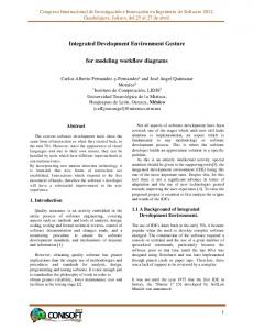
FIG. 2. Network emulated in GNS3
The network emulated in GNS3 is made up of a network that is configured with the OSPF (Open Shortest Path First) protocol [6]. It consists of intermediate equipment such as routers and switches, as well as end devices. The OSPF protocol [2] is a link-state dynamic routing protocol, unlike other routing protocols such as RIP (Routing Information Protocol) and IGRP (Interior Gateway Routing Protocol) that are distance-vector protocols. This means that all routes know the complete network topology and can make routing decisions without the risk of looping into the network. In the next figure the algorithm based on which the OSPF routing protocol works is presented, meaning the minimum cost route to a particular destination. As an example for this demonstration PC1 and PC2 were used.
FIG. 3. Trace route between PC1 and PC2
To set the costs on each interface, it was necessary to configure each router with the following parameters.
41
Real-Emulated-Simulated Integrated Environment for Testing Computer Networks
FIG. 4. Costs Checking on Router Interfaces 1
To start monitoring the network created in GNS3, the routers configuration is needed, using the SNMP protocol as follows:
FIG. 5. Configuration R1 with SNMP protocol
For traffic monitoring, and for network administration, the CACTI application was used. To monitor the topology created in GNS3, each device we wanted to monitor was implemented in CACTI [5]. To begin network monitoring, in the Graph Trees menu, a new database was created on the devices we want to monitor. Once the database has been created, it required the introduction of each device that we want to monitor. From the Devices menu, the device was selected and then Create Graph for this Host. After selecting the Create Graph for this Host menu, the type of router tracking we want from the Graph Types menu was selected. Also, two options for monitoring, traffic and processor loading can be selected. To start the device monitoring process in CACTI, is necessary to click on the Graph Trees menu, then select the database, TEST LICENSE TEST.
FIG. 6. Devices monitored with the CACTI application
42
Review of the Air Force Academy
No.1 (36)/2018
FIG. 7. Selecting the database
After completing the add-on process of the type of devices intended to be monitored, the router's monitoring process is started, instantiating the router processor request tracking charts, as shown in the figure below. Devices can be monitored for different periods of time, from the last half an hour to months or years. Monitoring is done on routers in different ways: the traffic on each interface, CPU usage.
FIG. 8. Selecting the monitoring period
43
Real-Emulated-Simulated Integrated Environment for Testing Computer Networks To receive the alarms related to a possible problem with a router, it will be monitored in a MIB browser, iReasoning being used in this case. It tries to restore the connection between the Fa0/1 interface of the router 2 and the F0/0 interface of the router 3. As long as the interface is administratively closed, the transfer of the packets between source and destination is done on another route. When the status of the interface monitored in its original state was changed, iReasoning issued a warning message about how to restore the status of the interface to its original state.
FIG. 9. The appearance of a warning about the incorrect operation of an interface
4. CONCLUSIONS In order to integrate service-oriented modern IP techniques and computer network monitoring, specialized literature was consulted in order to identify and choose the most modern working technologies. The test-integration environments have become so powerful that the emulator can turn into a network manager. The analysers can instantiate graphical and statistical representations in the nodes of the tested network for which the modern CACTI solution has been chosen and the scenarios can benefit from the decision-making functions offered by artificial intelligence for which the Management Information Base browser (MIB) was used. REFERENCES [1] *** uCertify.com, uCertify Guide for CompTIA Exam N10-004 Network, Pass your Network Certification in first attempt, 2010, ISBN-13: 978-1616910051; [2] H. Helmi, Monitor the Routing Using OSPF Protocol with Down State Neighbour, 2011; [3] A. S. Tanenbaum, Computer Networks, 4th Edition, Byblos, 2003; [4] D.M. Curpen, O.M. Machidon, Retele de calculatoare, Transilvania University Press, 2012, ISBN 978606-19-0177-7; [5] T. Bălan, D. Robu, F. Sandu, Integrarea Sistemelor de Calcul şi Telecomunicaţii, Transilvania University Press, ISBN 978-606-19-0609-3 [6] R. S. Zahidur, OSPF Network Routing, Scholars' Press, 2015; [7] L. Walsh, SNMP MIB Handbook, Wyndham Press, 2008; [8] D.T. Perkins and E. McGinnis, Understanding SNMP MIBs, Prentice Hall, 1996.
44