Jul 18, 2004 - by the OpenGL function gluUnproject. .... [4] ISO/IEC JTC 1/SC 29 14496-2, âInformation technology - Coding of audio-visual objects (MPEG-4) ...
REAL-TIME 3D GRAPHICS STREAMING USING MPEG-4 Liang Cheng, Anusheel Bhushan, Renato Pajarola, and Magda El Zarki School of Information and Computer Science University of California, Irvine, CA 92697 {lcheng61, anusheel, pajarola, magda}@ics.uci.edu July 18, 2004
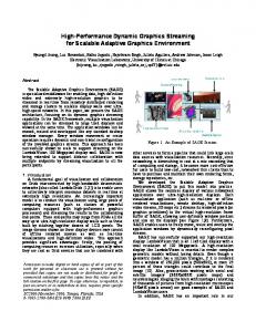
Abstract In this paper, we consider a real-time MPEG-4 streaming architecture to facilitate remote visualization of large scale 3D models on thin clients, which denote most of the hand-held devices that have limited computing resources. MPEG-4 serves as a key component to handle the compression, transmission, and visualization of the high-end supercomputer rendered image sequence, allowing the synchronization of the data in both the terminal and the server. The MPEG-4 encoding speed is thus the bottleneck of the system, in particular, the motion estimation process takes more than half of the total encoding time. We propose a fast motion estimation algorithm that expedites the MPEG-4 encoding process. Our algorithm utilizes the 3D data available at the server and is able to directly calculate the motion vector on a block basis without having to employ the expensive MPEG motion searching procedure. In addition, our algorithm can be implemented on the Graphic Processor Units(GPUs) such that most of the motion estimation process can be done in parallel to the encoding process. Our preliminary results show that the proposed motion estimation is able to significantly speed up the encoding process while maintaining the encoding quality.
1
1
INTRODUCTION
With rapidly expanding data sizes from scientific experiments, measurements and numerical simulations, the datapeople collocation problem becomes increasingly difficult to solve. Data to be visualized and analyzed cannot be moved in real-time to any location where scientists need access to it. In fact, not only the data but also the computing resources are often not portable. Interactive visualization of 3D data sets is one particular instance of such a data-people collocation problem. For example, if doctors want access to medical imaging data sets and interactively visualize CT or MRI scanner data, it requires doing so where the computing and visualization resources are located. The same holds for scientists visualizing simulation results. This, more often than not, is not the location where doctors or scientists collaborate or meet clients. The clients typically used for remote data visualization like cellular devices have low computing power. Moreover, specialized graphics hardware support is usually required to render huge data models at reasonable frame rates. In addition, limited bandwidth hinders the 3D models from being widely accessible to low-end devices. Thus, remote access and visualization of 3D data is a flexible approach that can accommodate for varying client graphics power and network bandwidth. In this paper we plan to explore an approach that brings 3D visualization to any network connected location by way of streaming 3D graphics. The idea is to define a client-server architecture that by exploiting the state-of-theart video streaming techniques allows interactive visualization of 3D environments and data sets on clients with thin computing and rendering resources. Within this architecture, the clients send commands and manipulate the 3D models that are stored at the remote server. The visualization server performs 3D rendering and streaming, allowing the clients to view the results of their requests in real-time. Unlike conventional video streaming, the server should enable the transmission of real-time encoded video from 3D graphics instead of pre-compressed video. Hence, one of the key problems for the proposed architecture is to expedite the encoding process such that the delay at the server is reduced.
2
A major challenge in MPEG-based video encoding is the motion-vector estimation stage. While discrete cosine or wavelet transformation on pixel blocks, vector quantization and entropy coding stages of an MPEG codec have limited time cost, motion estimation involves a time-consuming block matching, which takes more than half of the total encoding time. Over the past years, varied fast motion search methods are proposed, such as [1]. However, block matching method is still considered as the only way to estimate the video motion vector. Unlike natural video, for a graphics rendered video, information of the rendering process can be used to devise a more efficient motion estimation strategy. [2] and [3] talked about such an approach, where they both use information of the rendering process to predict the motion vectors and combine them with a conventional motion search strategy. They use their method to provide a good starting guess for MPEG based motion searching. Their methods, when comparing to the conventional MPEG motion estimation with limited searching range, offer considerable gain. This is because some of the blocks have large motion vectors and the MPEG motion estimation with limited searching range cannot reach their matching blocks in the reference frame. However, if we increase the searching range, MPEG motion estimation could have similar result as these schemes. Moreover, because they still employ motion searching for each block, their schemes are not significantly faster than the conventional searching scheme.
In this paper, we propose to better utilize information of the rendering process to achieve a much faster motion estimation. Specifically, we calculate the motion vectors as part of the rendering process itself with minimal overhead. We are able to directly calculate the motion vector on a block basis without having to employ the expensive MPEG motion searching procedure. The programmable graphics pipeline available in today’s GPUs allows us to calculate the per pixel displacement. Together with the color frame-buffer, the 3D rendering engine also provides the z-buffer information for each frame. As the graphics server has full information of the 3D geometry, the user viewpoints and the generated images of consecutive frames, it can in fact exactly compute where a pixel in frame number i + 1 was visible, if at all, in the reference frame number i. Each pixel can thus be projected back to the 3D model from different viewpoints. 3
Also, by comparing the depth values, we can determine visibility of a pixel from different viewpoints. The obtained motion vectors are directly incorporated into the encoding loop without going through any block matching. Moreover, our motion estimation computation is accomplished on the Graphics Processing Unit(GPU), which considerably lowers the load of the CPU and thus further accelerates the encoding speed. The GPUs are stream processors that are specifically targeted at fast processing of such streaming graphics data. Moreover, the GPU and CPU work in a pipeline structure enabling higher frame rates. Our proposed algorithm is composed of two parts: (1) the acquisition of the precise per pixel motion vectors given the known geometry and (2) the conversion of the per pixel motion vectors to per block motion vectors, as well as the selection of the block types, including 16 × 16 and 8 × 8. We only use the full MPEG searching method for macroblocks whose motion vectors cannot be directly acquired by our method. The number of these macroblocks is however very low. The rest of the paper is organized as follows. In the section 2, we will present the architecture of our proposed 3D streaming system. In the section 3, we will discuss some basic fundamentals of MPEG-4 [4] encoding. In the section 4, we will explain our motion vector estimation algorithm. Section 5 shows our simulation results. We will conclude our work and discuss the future work in section 6.
2
SYSTEM OVERVIEW
A high-level framework of the anticipated client-server 3D streaming and rendering system is given in Figure 1. The whole framework can be vertically divided into three planes: control plane, data plane, and transmission plane. The control plane is responsible for the translation of the user’s interactivity and its transmission. The user interactivity includes the object’s moving, spinning, and other 3D scene control commands. These commands are in turn encapsulated and transmitted by Transport Control Protocol(TCP) to the server side, where the Command Request Handler translate these commands into the parameters that can be recognized by the 3D 4
Control 3D Scene Database Data
Co mmand Request Handler
TCP socket
TCP socket
Hu man User Interface
3D Data Access Module MV Module
3D Renderer
Co mmand Manager
Video Renderer IP Network MPEG-4 Decoder
MPEG-4 Encoder Transmission RTP/ UDP/IP socket
RTP/ UDP/IP socket
Server
Client
Figure 1: System Architecture. Data Access Module. The TCP protocol guarantees the reliability of the whole control plane. Our contribution in this paper essentially reside on the Data plane. The 3D Data Access Module retrieves the 3D data from the 3D Scene Database and renders the data with the desired parameters, such as the viewpoint and size, with the aid of the graphics processing units (GPUs). That is, the entire interactive 3D rendering is performed on the graphics server. Meanwhile, at the MV Module, the 3D model data and the received parameters are used to generate the per-pixel and per-block motion vector estimates. This calculated motion data enables a faster and more accurate motion estimation, which may replace the motion searching process featured by the MPEG-4 encoder. The rendered image sequence is compressed by the MPEG-4 encoder before entering the network. In our system, real-time protocol (RTP) [5] is used to ensure the promptness of the data transfer. At the client side, the received stream is in turn received, unpacketized and decoded. The decoding module only consists a regular MPEG-4 decoder and a raw-video renderer, which is feasible for thin client devices, such as the hand-held computers or wireless phones. The most time consuming modules in the pipeline are the motion vector estimation and the transmission
5
modules. Thus, increasing the compression ratio of the encoding or reducing the motion estimation time would increase the frame rate of the overall system.
3
MPEG-4 motion estimation
MPEG-4 is designed for the video streaming over the bandwidth constrained network. The MPEG-4 encoding process is, however, CPU intensive and time consuming, especially when compressing a high resolution video sequence. In this section, we will describe the basis of the traditional MPEG-4 motion estimation and encoding procedure. The most time-consuming process in the motion video encoding is known to be motion estimation, which uses the temporal redundancies between frames by predicting motion of macroblocks from the reference frames as shown in Figure 2. A block matching method is commonly used for prediction whereby the best match from the reference frame is the one with the lowest residual error between itself and the current source macroblock being coded. This residual error is then DCT transformed, quantized and coded by using variable length coding (VLC).
Current Frame
Previous Reconstructed Frame
Figure 2: Motion Estimation. The Block Matching algorithm involves computing the sum of absolute difference (SAD) between the current macroblock and candidate blocks of the reference frame using Equation 1. S(i, j) denotes the pixel value on the ith column and j th row in the current macroblock. p × p refers to the size of the block. R(i, j) denotes the corresponding value in the reconstructed reference image. u and v range from −w to w, as is seen in Figure 4. w × w thus equals the number of block matching candidates. 6
Current Frame
Previous Reconstructed Frame
Figure 3: 4MV Motion Estimation.
SAD(u, v) =
p � p �
|S(i, j) − R(i + u, j + v)|,
(1)
i=1 j=1
p+2w w p+2w
p w
p
w
w
Figure 4: Block Matching. The state-of-the-art video compression standards, such as MPEG-4 [4], achieve superior quality by using finer block matching and increasing the range of the motion estimation. For example, the 4-motion-vector mode (4MV) option is included in the MPEG-4 basic toolset. The 4MV is illustrated in Figure 3. The extended motion searching range is up to [-1024, 1024] in pixel units. However, the processing time increases linearly with the number of block types used and the size of the searching range, as is seen in Equation 1. For each 16 × 16 block, we have up to 4198401 motion vector candidates. Furthermore, the motion searching mode (i.e., either 16 × 16 7
or 8 × 8) has to be determined. The task of block type decision and full motion searching in real-time is thus formidable. Of course, a smaller searching range [−8, 8] is usually allowed and the 4M V mode can be disabled by the encoder to reduce the low encoding latency. This, however, leads to a degradation in the coding efficiency. Motion estimation is thus the most time consuming part of the MPEG encoding process. Using a fast motion estimation strategy can significantly speed up the encoding.
4
GPU BASED MOTION VECTOR CALCULATION
In this section, we will describe our fast motion vector estimation algorithm using information of the rendering pipeline. The process is composed of two steps: (1) the acquisition of the per pixel motion vectors and (2) the conversion from the per pixel motion vectors to the per block motion vectors.
4.1
Per pixel motion vectors
We make use of standard z-buffered raster graphics hardware for rendering. The frame buffer stores the attributes (intensity or shade) of each pixel in the image space; while the depth buffer stores the z-coordinate, or depth of every visible pixel. This depth information is used to calculate the precise motion vectors between successive viewpoints. There is no search involved in estimating the motion vectors. The rendering process consists of projecting each 3D primitive onto the image plane. Figure 5 shows this image formation process from two successive viewpoints. Given the viewpoints and the projection parameters, the projection matrix M can be calculated, that takes 3D points X to pixels x in the image i.e. x = M X. This projection of 3D points to 2D image pixels is performed by the OpenGL[6] function gluproject as used in Figure 6. If we reverse this process, each pixel x in the image can be projected back into a ray M −1 x. The corresponding 3D point X lies on this ray(shown in green). Given the depth estimate z of X, we can find X by taking the intersection of the z plane with the ray. The back projection using the depth estimate is performed by the OpenGL function gluUnproject. 8
x
x1
x2
C1
C2
Figure 5: Motion Estimation. We wish to find an estimate for the motion vector of each pixel in the destination image. This procedure is shown in Figure 6. For each pixel x2 in the destination image, we project x2 back to its corresponding 3D point X. The corresponding pixel x1 can then be found by taking the projection of X using the camera C1 . However, if a pixel is occluded in the source image, the depth estimate of the pixel found by projecting it in the source image will not match the actual depth value at that pixel. This test can be used to identify such pixels and a more expensive MPEG motion searching can later be used to find the motion vector for this pixel. We flag such pixels as occluded pixels. These pixels however constitute a small percentage of the total pixels. Hence, we can calculate the precise motion vectors for majority of the pixels without having to employ an expensive search procedure. Moreover, this calculation is done on the GPU which is optimized for such streaming computations.
9
Per-pixel motion estimation () for each pixel x2 in destination image X = gluUnproject(x2 ,depth in destination image, C2 ) < x1 , projected depth in source image > = gluproject(X, C1 ) if (projected depth in source image �= actual depth in source image) flag x2 as being occluded in source image. if (projected depth in source image ∼ actual depth in source image) motion vector[x2 ] = x2 - x1 .
Figure 6: Per-pixel Motion Estimation Algorithm.
4.2
Per block motion vectors
Given the per-pixel motion vectors, we need to calculate motion vectors for 8 × 8 and 16 × 16 pixel blocks. This procedure is shown in Figure 7. The motion vector for a block can be found by simply taking an average of the motion vector values calculated for individual pixels in the block. This constitutes the most frequently occuring case. However, in the case when there are a large number of occluded pixels (i.e., larger than a threshold ρ), this estimate would not be optimal. Thus, we use MPEG motion vector estimation to calculate the motion vector for this block. Also, if the per pixel motion vector values in a block have a high variance (i.e. higher than a threshold σ), our scheme provides a good starting point for the MPEG search. Different settings of the parameters ρ and σ allow a trade-off between the time for motion estimation and the size of the encoding. From our simulations, we found the number of these uncertain macroblocks is not significant, compared to the total number of macroblocks (≤ 15% in our experiments). That is, we save at least 85% of the search time
10
Block motion vector estimation () for each block in destination image compute number of occluded pixels if (number of occluded pixels/block size > ρ ) /∗ Too many occluded pixels ∗/ use MPEG4 motion search to find motion vector for this block. else compute average motion vector and variance motion vector if (variance motion vector > σ) /∗ motion vectors in the block have high variance ∗/ use Mpeg4 motion search to find motion vector for this block. else block motion vector = average motion vector
Figure 7: Block Motion Vector Estimation.
regardless of the searching strategy, thereby considerably speeding up the encoding process.
5
SIMULATION
We used the MPEG-4 reference code[7] developed by Microsoft in our simulations. We made modifications in its exhaustive motion estimation module, using the GPU generated motion vectors in run time. For the macroblocks whose motion vectors cannot be determined, the normal exhaustive motion searching procedure was followed.
11
Any faster motion searching strategies can actually be used to replace the exhaustive motion estimation and achieve faster motion estimation. We use the 3D geometry information to get per-pixel motion vectors, based on which we obtain the per block motion vectors in different block sizes. MPEG-4 supports two block modes: 8 × 8 and 16 × 16. Hence, for each macroblock, we have five motion vector values: one for 16 × 16 and four for 8 × 8. The MPEG-4 encoder determines the encoding mode based on the SAD between the current block and its reference block. The mode decision procedure is described in Figure 5. MPEG motion estimation mode decision () SAD8 = SAD8 topLef t + SAD8 topRight + SAD8 bottomLef t + SAD8 bottomRight; if (SAD8 < SAD16) 4M V mode = TRUE; else 4M V mode = FALSE;
Figure 8: MPEG motion estimation mode decision.
The testbed server consisted of an Intel Pentium 4(1.99 Ghz) with a 512 MB DDR system memory and a PNY 980XGL Quadro 4 128MB 8X AGP Video Adapter. The server and client machines were connected together to a D-Link 100 Mbit switch. The testing sequence is a continuous stream of rendered images from the 3D model of a “Bone”, as is seen in Figure 9-a. The image resolution is 512 × 512. We manipulate the 3D model and generate three sequences representing three typical visualization processes: fast translation, rotation, and fast rotation followed by zooming.
12
Through all of our tests, we use variable bit rate encoding and set the quantization parameter as 10. Thus, we have similar quality (as is seen in Figure 9-b and Figure 9-c), but with different compression rate for these two motion estimation methods.
(a)
(b)
(c)
Figure 9: The first frame of the sequence “bone”. (a) is the original image. (b) is the reconstructed image by MPEG-4. (c) is the reconstructed image by the proposed scheme.
The simulation results coincide with our expectation. In Figures 10-a, Figure 11-a and Figure 12-a, we show that the proposed method significantly reduced the time used for the motion estimation. This is as expected, since most of the macroblocks are exempted from the expensive motion search computation. The search time for both motion estimation methods rises with an increase in the search range. This is because the number of the motion matching candidates increase. Note that the proposed scheme cannot determine the motion vectors of some macroblocks, which in turn are subject to the MPEG motion search. These macroblocks actually determine the significant part of the motion estimation time of the proposed scheme. However, these macroblocks constitute a small fraction of the total. In Figure 10-b, Figure 11-b and Figure 12-b, we notice that the proposed scheme has a slightly higher compression rate than the MPEG-4 motion searching methods. As is seen in Figure 11-b, the compression ratio
13
for the motion estimation doesn’t always rise with the increase in the search range, whereas in Figure 10-b and Figure 12-b, we observe a more consistent increase in the compression rate. This is because in Figure 11-b, the motion is slower than that in Figure 10-b and Figure 12-b. 900
Time (ms)
700
Compression Ratio
3d mpeg
800 600 500 400 300 200 100 0 2
4
6
8
10
12
200 180 160 140 120 100 80 60 40 20 0
3d mpeg
2
14
4
6
Search Range
8
10
12
14
16
Search Range
(a)
(b)
Figure 10: Fast translation. (a) is the motion estimation time. (b) is the compression rate.
900
Time (ms)
700
Compression Ratio
3d mpeg
800 600 500 400 300 200 100 0 2
4
6
8
10
Search Range
12
14
200 180 160 140 120 100 80 60 40 20 0
3d mpeg
2
16
4
6
8
10
12
14
Search Range
(a)
(b)
Figure 11: Slow rotation. (a) is the motion estimation time. (b) is the compression rate.
14
16
900
Time (ms)
700
Compression Ratio
3d mpeg
800 600 500 400 300 200 100 0 2
4
6
8
10
12
14
16
200 180 160 140 120 100 80 60 40 20 0
3d mpeg
2
4
6
8
10
12
14
16
Search Range
Search Range
(a)
(b)
Figure 12: Fast rotation and zooming. (a) is the motion estimation time. (b) is the compression rate.
6
CONCLUSION
In this paper, we propose a real-time MPEG-4 based streaming architecture that enables remote manipulation and visualization of 3D data on a thin client. To accelerate the MPEG-4 encoding process, we developed an online algorithm to calculate the block motion vectors using 3D information without having to employ an expensive search. Moreover, this computation is performed on the GPU, which can be performed in parallel with the video encoding. We use MPEG block matching technique to further search for the blocks whose motion vectors cannot be directly determined. The experiments showed that these uncertain blocks constitute a small percentage. Considering that the motion estimation process normally takes more than half of the MPEG encoding time, our GPU based motion estimation significantly expedites the encoding process while maintaining the encoding size. Changing σ and ρ leads to a trade-off between the encoding efficiency and the motion estimation time. In our future work, we plan to further study the roles of these parameters to accommodate for varying client graphics power and network bandwidth. Also, since the proposed GPU based motion estimation can be applied to the blocks with arbitrary shape and size, we are investigating its application to the emerging H.264/AVC [8] encoding standard, which supports up to seven types of block in the motion estimation process.
15
References [1] R. Li, B. Zeng, and M.L. Liou, “A new three-step search algorithm for block motion estimation,” IEEE Trans. Circuits System, Video Technology, vol. 4, Aug. 1994. [2] Y. Noimark and D. Cohen-Or, “Streaming scenes to mpeg-4 video-enabled devices,” Computer Graphics (Web Graphics), Feb. 2003. [3] D. Wallach, S. Kunapalli, and M. Cohen, “Accelerated mpeg compression of dynamic polygonal scenes,” IEEE Computer Graphics (Proc. SIGGRAPH), Jul. 1994. [4] ISO/IEC JTC 1/SC 29 14496-2, “Information technology - Coding of audio-visual objects (MPEG-4) Part 2: Video, international standard,” 2002. [5] H. Schulzrinne, S. Casner, R. Frederderick, and V. Jacobson, “RTP: A transport protocol for real-time applications,” IETF RFC 1889, Jan. 1996. [6] M. Woo, J, Neider and T. Davis, OpenGL Programming Guide, Addison-Welsley, 2000. [7] “Information technology - Coding of audio-visual objects (MPEG-4) Part 5: Reference software,” 2001/Amd 1: 2002. [8] Joint Video Team (JVT) of ISO/IEC MPEG and ITU-T VCEG, “Joint Model Number 1, Revision I(JM-1r1),” ITU-T SG16 Q.5 (VCEG) and ISO/IEC JTC 1/SC 29/WG 11 (MPEG), 2002-01-18.
16