modules needed for simulating real-time virtual humans in distant virtual ... For head and hands we use software called
. Animating Virtual Humans
Real-Time Animation of Realistic Virtual Humans R
ecent innovations in interactive digital television1 and multimedia products have enhanced viewers’ ability to interact with programs and therefore to individualize their viewing experience. Designers for such applications need systems that provide the capability of immersing real-time simulated humans in games, multimedia titles, and film animations. The ability to place the viewer in a dramatic situation created by the behavior of other, simulated digital Our system of simulating a actors will add a new dimension to existing simulation-based products virtual human allows realfor education and entertainment on interactive TV. In the games market, time animation of the body, convincing simulated humans rejuvenate existing games and enable head, and hands with the production of new kinds of games. Finally, in virtual reality deformations. A (VR), representing participants by a virtual actor—self-representation in CyberTennis game and the virtual world—is an important factor for a sense of presence. This CyberDance performance becomes even more important in multiuser environments, where demonstrate its capabilities. effective interaction among participants contributes to the sense of presence. Even with limited sensor information, you can construct a virtual human frame in the virtual world that reflects the real body’s activities. Slater and Usoh2 indicated that such a body, even if crude, heightens the sense of presence. We have been working on simulating virtual humans for several years. Until recently, these constructs could not act in real time. Today, however, many applications need to simulate in real time virtual humans that look realistic. We have invested considerable effort in developing and integrating several modules into a system capable of animating humans in real-time situations. This includes interactive modules for building realistic individuals and a texture-fitting method suitable for all parts of the head and body. Animating the body, including the hands and their deformations, is the key aspect of our system; to our knowledge, no competing system integrates
42
September/October 1998
Prem Kalra, Nadia Magnenat-Thalmann, Laurent Moccozet, and Gael Sannier University of Geneva Amaury Aubel and Daniel Thalmann Swiss Federal Institute of Technology
all these functions. We also included facial animation, as demonstrated below with virtual tennis players. Of course, real-time simulation has a price, demanding compromises. Table 1 compares the methods used for both types of actors, frame-by-frame and real-time. Real-time virtual-human simulation environments must achieve a close relationship between modeling and animation. In other words, virtual human modeling must include the structure needed for virtual human animation. We can separate the complete process broadly into three units: modeling, deformation, and motion control. We have developed a single system containing all the modules needed for simulating real-time virtual humans in distant virtual environments (VEs). Our system lets us rapidly clone any individual and animate the clone in various contexts. People cannot mistake our virtual humans for real ones, but we think them recognizable and realistic, as shown in the two case studies described later. We must also distinguish our approach from others. We simulate existing people. Compare this to Perlin’s scripted virtual actors3 or to virtual characters in games and films like “Doom,” Lara Croft characters from “Tomb Raiders,” or Toy Story heroes.
Constructing real-time virtual humans Computer graphics gives us the power to model and animate virtual humans. To simulate humans requires real-time visualization and animation, taking into account constraints on the data used for these avatars (virtual humans representing users). For example, scanning devices provide a fast method for constructing avatars, regardless of meta-information within the data. Real-time animation requires a small number of polygons and specific data structures to accelerate the computing process. Due to differences in modeling and animation between head, hands, and body, we divide our virtual humans into separate parts. Table 2 shows our methods and tools.
Sculpting the shape For head and hands we use software called Sculptor,4 dedicated to modeling 3D objects. This sculpting
0272-1716/98/$10.00 © 1998 IEEE
.
Table 1. Comparison between frame-by-frame and real-time virtual humans.
Surface Modeling Deformations Skeletal Animation Locomotion
Grasping Facial Animation
In Virtual Environments In the Real World Shadow Clothes Skin Hair
Frame-by-Frame Virtual Humans
Real-Time Virtual Humans
No limitations on complexity May be calculated using metaballs, FFD, splines Any method may be used
Limitations on the number of polygons Requires fast transformations, for example based on cross-sections
Any model/method may be used: motion capture, kinematics, dynamics, biomechanics Complex models may be used, including inverse dynamics Complex models may be used, including muscles with finite elements Not applicable May be composed offline using a video composer True shadows may be computed Autonomous clothes calculated using mechanical models Model with wrinkles Individual hairs possible
Requires real-time processing, which may prevent using expensive methods based on inverse dynamics or control theory Dynamic models may be too CPU intensive
Kinematics and heuristic methods should be used Simplified models should be used; limitations on the facial deformations No specific problems except limitations for immersive applications Requires real-time blending using a powerful video card Only shadows of approximate primitives may be calculated Texture mapping Texture mapping Only a polygonal shape with possible texture may be applied
Table 2. Methods and tools for modeling, animation, and deformations.
Head/Face Body
Hands
Modeling Method
Modeling Tool
Animation Method
Animation Tool
Deformation Method
Deformation Tool
Polygon mesh deformation Multilayer approach (metaballs) Polygon mesh deformation
Sculptor
MPAs
Face
Rational FFDs
Dodylib
BodyBuilder
Skeletal animation
Track
Contour manipulation
Dodylib
Sculptor
Skeletal animation
Track
Dirichlet FFDs
Dodylib
approach relies on local and global geometric deformations. Basic features provided by Sculptor include adding, deleting, modifying, and assembling triangle meshes. Real-time deformations and manipulation of the surface give designers the same facilities as real clay or wax sculpting. Head modeling. Using the Sculptor program instead of a scanning device while modeling the head lets us take into account the constraints of real-time animation. Manipulating objects in real time requires as few polygons as possible, while beautifying and animating the 3D shape requires more polygons. Designing the head with this program lets us directly create an object with the appropriate number of polygons. We can do this knowing which region needs animation (requiring lots of polygons) and which region requires less or no animation (needing fewer polygons). Designers can also model simpler objects knowing the texture will add
specific details, like wrinkles and shadows. Starting with a prototype head accelerates the creation process. Figure 1 on the next page shows modeling a face by starting with an already existing one. The more prototypical heads we have, the less time we need to spend. With no prototype, the designer can model half of the head starting from a simple primitive like a hemisphere and use a symmetric copy for the other half. In the final stages, however, the designer should make small changes on the whole head because asymmetric faces look more realistic. Hand modeling. We use two basic sets of 3D hands, one for each gender. The existing male hands were refined to give a feminine look using the interactive sculpting tool. The proposed hand simulation model lets us model morphological variations. Deformations of the muscular layer can be parameterized according to some morphological changes, such as hand thickness or skele-
IEEE Computer Graphics and Applications
43
. Animating Virtual Humans
1 Head created from a template in the Sculptor program.
articulated skeleton hierarchy schematically similar to a real human skeleton. You can define all the human postures using this skeleton. The virtual human’s proportions are designed at this stage, as described later.
(a)
2 Changes in various hand morphologies: (a) the middle finger lengthened, (b) the thumb extended from the hand and its size modified, and (c) an increase in the hand’s thickness.
(b)
(c)
ton finger length. The muscle layer is first fitted to the skeleton or scaled to the given morphological parameters, then the muscular operators are applied to the hand surface to create a new hand. The resulting new hand data set can then be used directly for animation. In Figures 2a and 2b, morphology changes are parameterized by the underlying skeleton’s changes. Figure 2c shows a global morphology change: the thickness of the hand increases. This change is parameterized independently from the skeleton.
Body creation BodyBuilder software helps in creating human body envelopes. We wanted realistic and efficient human modeling that let us use this data for real-time motion and deformation. We developed a multi-layered approach for the design of human bodies,5 as follows. First layer. The first layer provides an underlying
44
September/October 1998
Second layer. The second layer consists of grouped volume primitives, which fall into two categories: blendable and unblendable. Also known as metaballs or ellipsoids, these volume primitives have different colors depending on their selected functions: blendable or unblendable, deformable or nondeformable, or positive or negative shapes. Because metaballs can be joined smoothly and gradually, they give shape to realistic, organic-looking creations suitable for modeling human bodies. Attached to the skeleton’s proximal joint, they can be transformed and deformed interactively to define the 3D shape of a virtual human. Figure 3 shows male and female human body prototypes constructed by positioning, scaling, and rotating these volumes as well as attaching them to a desired joint articulation of the avatar’s skeleton. Designers can start from a simplified structure leading to a rough shape, then go back into the model by increasing the number of volumes. The latter technique gives— step by step—a higher level of detail. The human form is a very complex shape to reproduce. Modeling it proves tedious, since the human eye is very sensitive to inaccuracies in the human figure. The most challenging part is to manipulate these volumes in a 3D environment to simulate the muscles’ shapes and behaviors. Therefore, this kind of assignment requires strong skills in anatomy or in drawing and sculpting human figures. Third layer. The third layer is the equivalent of the human skin. We define the body envelope with spline surfaces using a ray-casting method. In this way, metaballs have observable effects on the surface shape. We use this approach because human limbs exhibit a cylindrical topology, and the underlying skeleton provides a natural centric axis upon which we can define a number of cross-sections.
Texture fitting A well-known method in computer graphics, texture mapping improves virtual objects’ quality by applying
.
3 real images onto them. Its low cost in terms of computation time proves very useful for real-time applications. For virtual humans, the texture can add grain to the skin, including details like variations in the hair and mouth color. These features require correlation between the image and the 3D object. A simple projection doesn’t always realize this correlation: the object—designed by hand—can differ slightly from the real image. An interactive fitting of the texture is required. In Figure 4, the wrinkles of the hands have been fitted to the morphology of our 3D model. Figure 4a shows the texture applied to the 3D hand shown in Figure 4b. We developed a new program for fitting the texture to the 3D object’s features.6 The program enables the designer to interactively select a few 3D points on the object, which are then projected onto the 2D image. The projection can be chosen and set interactively, hence the designer can adjust these projected points to their correct position on the image. This method obtains the texture coordinates for the selected 3D points. One problem faces us with this method, however: we want to avoid interactive specification of the texture coordinates for all the 3D points needed to map a whole surface. We implemented a method for finding these texture coordinates by interpolating from the already existing ones. Thus, all the 3D points are projected onto the 2D image. Using a Delaunay triangulation with the 2D points marked, we can select which points are projected inside the Delaunay area—those belonging to the 3D surface to be textured. The barycentric coordinates are calculated for all the projected points inside a Delaunay triangle, giving the position of each. After the motion of a marked point (vertex of a Delaunay triangle), the positions of the projected points are recalculated using their barycentric coordinates. Finally, the texture coordinates of all the surface’s 3D points are given by the positions of the corresponding points on the image.
Animating the body A real-time virtual human is one that can act at the same speed as a real person. Virtual reality, interactive television, and games require real-time virtual-human
Male and female human body modeling using metaballs.
4 (a) Texture; (b) applied to a 3D hand.
(a)
(b)
bodies. The generally accepted approach models the body in two layers, skeleton and skin; a third layer— cloth—could also be added. The skeleton layer consists of a tree-structured, fixed-topology hierarchy of joints connecting limbs, each with minimum and maximum limits. The skin layer, attached to the skeleton, generates the skin surfaces of the body. Animation of the virtual body affects the skeleton layer. Animation of skin and cloth are automatically computed by deforming or transforming vertices. This means that the skeleton animation doesn’t normally depend on the two other layers and could be defined in very different ways (as shown in the next section).
Skeleton animation Motion control lies at the heart of computer animation. In the case of a digital actor, it essentially assists in describing, with respect to time, the changes to the joint angles of a hierarchical structure called “skeleton.” Hierarchical skeleton. Based on a general hierarchy manager library, we built a specialized library to model the human body. This hierarchy is defined by a set of joints, which correspond to the main joints of real humans. Each joint consists of a set of degrees of freedom (DOF), typically rotation and translation, which can vary between two limiting values based on real human mobility capabilities. Applying a set of scaling methods to several points of this skeleton obtains different bod-
IEEE Computer Graphics and Applications
45
. Animating Virtual Humans
ies in terms of size (global scaling of body parameters) and characteristics (local scaling like spin, or lateral or frontal scaling). Our current virtual skeleton—the hierarchical model—totals 32 joints corresponding to 74 DOF, including a general position-orientation joint (6 DOF) henceforth referred to as the global joint.7 Once we have defined the body in terms of shapes and mobility, we use a global motion-control system to animate the virtual human skeleton within 3D worlds. Animating the joint angles over time accomplishes this. However, this type of animation strongly relates to the type of motion control, as we’ll discuss next. Skeleton motion control. We see three distinct categories of approaches to skeleton motion control for virtual humans. 1. The skeleton motion, captured in real time, drives a pure avatar. A participant actor—the avatar—is a virtual copy of the real user. This actor’s movements exactly reflect those of the real user, meaning that the skeletal motion must be determined in real time to interactively animate the avatar. A teleconferencing application clearly illustrates this: multiple participants from distant sites can share, move, and act within the same 3D environment.8 This approach requires many sensors to track every degree of freedom in the real body. However, limitations in the technology and number of sensing devices generally make this impossible. Therefore, the tracked information is used in conjunction with human animation behavioral knowledge and different motion generators to “interpolate” the untracked joints. Currently, the motion-capture system directly drives 34 DOF with 12 magnetic sensors. In addition, one digital glove controls 25 finger DOF and 2 wrist DOF. In addition, the motion can be recorded as keyframes and played back with additional information, such as the joints’ trajectories. This information helps in analyzing the motion for incremental improvements of a desired recording (especially for sports). The straightforward method for motion capture sets each body segment’s location by 6D data (position and orientation) from an attached sensor. However, for a variety of reasons this can produce abnormal relative translations between adjacent segments, giving the impression that the body is an unnatural and unrealistic collection of independent elements. Possible sources for the mismatch between the virtual model and the performer postures include ■ Calibration error ■ Slippage of the sensors with respect to underlying
bones ■ Electronic noise ■ Oversimplified rotational joints on the graphical
model To solve the problem, we developed an anatomical converter9 based on a very efficient method for capturing human motion after a simple calibration. The sensor
46
September/October 1998
data is converted into the anatomical rotations of bodies’ hierarchical representations. Such a choice facilitates a wider use of the motion for other human models with the same proportions. It’s also easy to integrate motion capture and immersion display devices, as the head-tracking sensor can both animate the neck joint (thus moving the model’s head) and set the viewing parameters for the head-mounted display. 2. The skeleton motion is selectively activated from a database of predefined motions. A guided actor is completely controlled in real time by the user, but the actions do not correspond directly to the user’s motion. The participant uses input devices to update the virtual actor’s position. You can exert this local control by computing the incremental change in the actor’s position and, for example, estimating the rotation and velocity of the center of the body. A simple method is to play back a specific sequence, for example by hitting a key or clicking the mouse in the right place. Again, you can use motion capture to solve this problem. The anatomical converter provides the ability to easily record keyframe sequences of all or part of the body. The design time is greatly reduced compared to pure keyframe design even if you plan a second stage of motion refinement after the capture. However, designing and combining these predefined movements requires combining various techniques to achieve realistic motion with relative efficiency. Consequently, we based our approach on integrated methods. Integrating different motion generators is vital for designing complex motion where the characterization of movement can quickly change in terms of functionality, goals, and expressivity. This induces a drastic change in the motion control algorithm at multiple levels: making behavioral decisions, optimizing global criteria, and actuating joint-level controllers. Until now, no global approach could reconfigure itself with such flexibility. Consequently, the Track system— an interactive tool for visualizing, editing, and manipulating multiple track sequences—has two major goals. First, it integrates a wide range of motion generators within the unified framework of multiple track sequences, and second, it provides a set of tools for manipulating these entities. A sequence is associated with an articulated figure and can integrate different motion generators such as walking, grasping, inverse kinematics, dynamics, and keyframing within a unified framework. The system provides a large set of tools for track space manipulations and Cartesian space corrections. 3. The skeleton animation is dynamically calculated. Applications like complex games or interactive drama need not only motion control but also a way of providing autonomy or artificial intelligence to virtual humans. By autonomy, we mean that the virtual human doesn’t require a viewer’s continual intervention. An autonomous actor may act without the user’s intervention. Autonomous actors can have behavior, thus must have a manner of conducting themselves. Behavior
.
doesn’t mean just reacting to the environment—it should also include the flow of information by which the environment acts on the animated creature, as well as the way the creature codes and uses this information. The behavior of autonomous actors relies on their perception of the environment. Typically, the actor should perceive the objects and other actors in the environment through visual, tactile, and auditory virtual sensors.10 The actors’ behavioral mechanism will determine the actions they perform based on the perceived information. Actors may simply evolve in their environments. Alternatively, they may interact with these environments or even be aware of other actors and real people. Moreover, they can communicate interactively with other actors, whether real or virtual. With such an approach, we should be able to create simulations of situations such as digital actors moving in a complex environment they may know and recognize, or playing ball games based on their visual and tactile perception. The referee in the tennis game described later typifies an autonomous virtual human. A collaborative application can combine a virtual human controlled by a participant with autonomous virtual humans controlled by internal engines. We should also mention the hybrid case where predefined motion is dynamically replayed based on the autonomous actors’ decisions and not in response to user intervention.
Body deformations Few attempts at producing virtual humans have reached the right compromise between realism and animation speed. On the one hand, some applications emphasize speed and interaction. Typically, they use a polygonal representation: the skin wrapped around the skeleton is represented with a fixed mesh divided at important joints where deformations occur. Because no deformations are computed within a body part—that is, between two joints—the virtual human appears “rigid” and lacks realism. Moreover, visually distracting artifacts may arise at joints where two body parts connect, for example when limbs are bent. On the other hand, some applications stress visual accuracy. Such applications generally compute the skin from implicit primitives and use a physical model to deform the body’s envelope. Though this approach yields very satisfactory results in terms of realism, it proves so computationally demanding that it’s unsuitable for real-time applications. We investigated a third approach that combines some elements of the previous ones, allowing a good tradeoff between realism and rendering speed. Our simple yet powerful system smoothly deforms the skin, greatly enhancing the human appearance of our virtual characters while preserving a high frame rate to meet the real-time requirements of virtual environments. Constructing a body mesh. After modeling a virtual human in BodyBuilder and generating the three layers, we can output body data as cross-sectional contours. A (cross-sectional) contour is the set of coplanar, outermost points around a skeleton’s segment. Since BodyBuilder divides a human body into several logical
5
Arm deformation.
(a)
(b)
parts—neck, torso, shoulders, forearms, waist, pelvis, thighs, and calves—we get skin contours for these body parts as well. While dedicated graphics hardware doesn’t render complex primitives very well, it performs far better when rendering polygons, especially triangle meshes. It therefore seems logical to convert our data to triangle meshes. We can easily construct a triangle strip from two adjacent cross-sections by connecting their points. Thus, we can construct an entire triangle mesh for each body part directly from the contours’ points. Connecting two different body parts proves a bit more complicated, since the contours may have a different number of points, but the idea remains essentially the same. We eventually obtain a single, seamless body mesh. Deforming by manipulating skin contours. The basic idea for fast deformations of human limbs and torso is to manipulate the cross-sectional contours. This transforms a complicated 3D operation into a 2D operation that’s more intuitive and easier to control. We have seen that a contour is by definition a set of points that lie in a plane. By setting the orientation and position of this plane, we achieve a smooth deformation of the skin. First, every joint in the skeleton is associated with a contour. We make sure every joint lies in the plane of its contour when the skeleton is in the at-rest posture. If we consider the arm deformation as an example, as illustrated in Figure 5a and 5b, we have three joints and two segments whose directions are L1 and L2. Let Nu, N0, and Nl be the normal vectors of the cross-section planes at the segments’ ends. Note that these planes are precisely those mapped to the three joints. Consequently, the shoulder joint, elbow joint, and wrist joint respectively drive the orientation and position of Nu, N0, and Nl. Finally, let Oi and Ni be the center and normal respectively of the ith cross-section plane along the upper segment. Then, a simple interpolation of the two normal vectors N0 and Nu gives us Ni. If we now suppose Ni is the normal vector of the ith contour belonging to the forearm, we can similarly compute Ni by direct interpolation between N0 and Nl. Obviously, once the normal vector Ni is known, it becomes straightforward to compute the new local coordinates of each vertex Vj belonging to the ith contour (see Figure 5b). If you look closely at the region above the elbow in Figure 5b, you’ll notice adjacent contours that seem to run parallel, as if not deformed. That is indeed the case—we intentionally limited the number of contours deformed for each body part. This decision was moti-
IEEE Computer Graphics and Applications
47
. Animating Virtual Humans
than one third of the total rendering time. Obviously, the real bottleneck lies rather in the drawing process. Finally, because the deformable model needs fewer polygons, it follows that only a marginal difference exists between rendering a deformable model and a rigid one. These results show this technique’s promise. Note that Character Studio, a plug-in for 3D Studio Max dedicated to creating and animating bipeds, uses a similar technique to deform the skin. Its approach also uses cross-sections—in essence, what we have termed contours. Unfortunately, Character Studio is not intended for real-time applications.
6 Deformable (left) versus rigid (right) virtual humans. Note the shoulders, right elbow, top of left thigh, left wrist, and other areas for differences.
Animating hands
vated by the observation that even though real human beings’ skin deforms smoothly, some parts play a greater role visually than others. In fact, hardly any loss of visual quality occurs if a skeleton segment’s middle contours do not deform because our eyes naturally go to the areas surrounding major joints like the elbows or knees. Practically, we determined the number of upper and lower contours to deform in a heuristic fashion. On the whole this deliberate limitation pays off in the sense that it saves a considerable amount of rendering time, with very little degradation of the final image. Results. For the implementation, we used a realtime-oriented 3D graphics toolkit called Performer, available on all Silicon Graphics workstations. Figure 6 on the left shows a virtual human made up of 14,000 vertices and containing 13,500 textured triangles using deformations. Figure 6 on the right shows the same virtual human using rigid meshes (with 17,000 triangles because of the extra ellipsoids needed at joints). Table 3 summarizes the results for these models obtained on a single-CPU (R10000) Octane workstation. Although the hands, feet, and head appear in Figure 3, we don’t take them into consideration in the triangle count nor in the rendering timings displayed in Table 3. Computing the contour deformations accounts for less
Hands have gotten very specific treatment in real-time human simulations because using a deformable hand model is generally considered too expensive given its contribution to the global visual result. This approach closely relates to the optimization approach generally used in virtual environments (VEs): the level of detail (LOD).11 This approach mainly links an object’s importance to its rendered size relative to the final picture’s size. According to this hypothesis, hands should not get a lot of attention. We want first to justify the need for providing a realtime and accurate hand simulation model by briefly underlining the importance of hands in simulating humans inside VEs. We’ll then show how we developed a dedicated simulation model for the hand and parameterized it to simulate realistic hands for real-time environments.
Hands in human simulation Hands represent a very small part of the whole body. Artists’ rules for drawing humans define the ideal proportions: the whole body measures eight times the height of the head, and the length of the hand equals the height of the face. The hand’s width should equal half its height. Although canonical, these measurements give a good idea of the hand’s size relative to the whole body. We must consider its relative size, of course, but the hand’s importance is not restricted to this aspect. Mulder12 classified hand gestures into three main categories: ■ Semiotic: communicates meaningful information and
results from shared cultural experience. ■ Ergotic: associated with the notion of work and the
human capacity to manipulate the physical world and create artifacts.
Table 3. Rendering timings (in milliseconds). Average Time per Frame
Deformable Model when Motionless
On computations Drawing In total *
3.4 19.5 25.7
Rigid Model when Motionless
1.3 23.7 25.9
Deformable Model in Motion (all joints involved)
Rigid Model in Motion (all joints involved)
9.7 19.9 31.3
*Total rendering time differs from just computing and drawing because of extra processes like culling.
48
September/October 1998
1.4 24.2 29.1
.
■ Epistemic: allows humans to learn from the environ-
ment through tactile experience or hepatic exploration. These three categories show the hand’s importance in simulating a realistic human when interacting with a VE. The hand is both an effect and a sensor, providing a gateway between humans and their environment. This implies that hands are a center of interest and that despite their size, many situations during the simulation will focus on them. A convincing visual representation requires appropriately modeled and simulated hands. Hands concentrate many DOF; each hand contains 25 DOF. Since our skeleton model counts around 120 total DOF, that means the hands account for about 40 percent. As a result, the hands are the most flexible part of the body, and the total number of possible postures and movements is very large. Thus, the hand may have a high level of deformation, concentrated in a very short area. Moreover, a brief look at anyone’s hands shows that the main hand lines associated with the skeletal joints controls the muscular action and skin deformation. The hand’s importance requires more than the set of rigid, articulated skin pieces devoted to it in the traditional approach. Its particularities require a dedicated model. We propose a hand-simulation model suited for real time, to be used in conjunction with the traditional approach.
Basic hand multilayer model We proposed a multilayer model for simulating human hands13 as a part of the Humanoid environment.7 The basic model, which follows the traditional multilayer model for articulated deformable characters, subdivides into three structural layers: skeleton, muscle, and skin. We combined the approaches of Chadwick et al.14 and Delingette et al.15 to design the three-layer deformation model for hand animation. The intermediate muscle layer maps joint-angle variations of the basic skeleton layer into geometric skin deformation operations. It is based on a generalized free-form deformations (FFDs)16 model called Dirichlet FFDs (DFFDs).13 The structural muscle layer is modeled by a set of control points, attached to the skeleton, that approximate the hand skin’s shape. The skeleton’s motion controls the control points’ displacements. Once the control point set fits the skeleton’s current configuration, the generalized FFD function is applied to the triangle mesh representing the geometric skin. The relationship between the control points and the object to deform relies on a local coordinate system called Natural Neighbors (NN) or Sibson.17 For each vertex of the surface, this local coordinate system permits automatically defining a subset of control points whose displacements will affect it. This subset serves to build a deformation function similar to the one defined for FFDs. (The geometric deformation model is thoroughly described elsewhere.18) The deformation function, defined inside the control points’ convex hull, interpolates the control points’ displacements to the deformed surface’s vertices. Among all the resulting model’s properties, note the lack of a constraint on the location of the control points
7
Control points arrangement showing wrinkles.
Constraint control point Standard control point Inflation control point
and on the shape of their convex hull. Moreover, we do not need to explicitly define the topology of the control points set. All of the FFD extensions apply to DFFD, among them two of particular interest to our hand simulation model. We can assign weights to control points and define rational DFFD (RFFD)19 with an additional degree of freedom to control deformations. We can also perform direct surface manipulation with the basic model without having to use an estimation method. Since we can define any location in the 3D space as a control point, assigning a control point to a vertex on the surface lets us directly control its location: any displacement applied to the constraint control point is integrally transmitted to the associated surface vertex. We build the set of control points to match a simplified surface hand topography. From observing a hand, especially its topography, we derive the following basic data structure for our hand model. We call it a wrinkle, as shown in Figure 7. The wrinkle itself is a set of constraint control points. Generally selected around the joint, they form a closed 3D line of points we call wrinkle control points. Two points among the wrinkle control points define the axis on which the associated skeleton joint should lie. In this way, you can easily adapt a skeleton model to the hand’s skin. This data allows easy, realistic hand-skeleton mapping by defining an implicit skeleton to which you can fit the skeleton. A mixed set of control points and constraint control points surrounds the upper part of the hand surface affected by rotation of the joint associated with the current wrinkle. We call these points influenced wrinkle control points, as they are influenced by rotation of the wrinkle itself. One control point, called an inflation control point, simulates inflation by the upper limb associated with the joint. For each wrinkle, the muscle layer gets the joint angle variation from the skeleton layer. If the rotation angle is α, the wrinkle itself is rotated at an angle of α/2, and the set of influenced control points is rotated at α. At the rest position, all control points have a weight of 1. When the
IEEE Computer Graphics and Applications
49
. Animating Virtual Humans
nence; (9) finger first line; (10) finger second line; and (11) finger third line. Figure 9 shows how control points, constraint control points, and inflation control points are designed around the surface of the hand to build the control points set and the different wrinkles.
(11)
(10)
Optimizing the deformation function (2)
The complexity of our basic muscular deformation model relates to the
(9)
8
Topography of the hand. (3) (7) (1)
(6)
(4) (5) (8)
9 Control points set and wrinkles design (top). Hand posture with various constrained Sibson control points (bottom).
■ degree of the deformation function and ■ number of control points involved.
In this optimization step we aim to provide a deformation function that can work at different levels. We introduce a deformation level of detail (LOD), similar to a geometric LOD. Optimization results from parameterizing the deformation function with two features that constrain the function complexity. The real-time hand simulation model works on a fixed geometric LOD. We chose this approach because a realistic hand shape requires high resolution, and performing deformations is worthwhile only for a minimum resolution of the deformed surface. As for basic FFDs, the deformation function is a cubic function of the local coordinates. The deformation function’s properties make it usable at lower degrees with a minimal loss in the continuity of the deformation. We can then choose between a linear, quadratic, or cubic deformation function. The total number of control points in a vertex’s deformation isn’t predefined and depends on the local configuration of the control points’ set located at the vertex inside the convex hull of control points. You can control and constrain the number of control points between 4 and the “natural” number of NN control points. Note that limiting the number of control points to 4 results in a continuity problem—the price for the gain in speed. Figure 10 shows, for the same hand posture, three different results with various constrained Sibson control points. Figure 10a shows the basic DFFD function. Sibson control points are constrained to a maximum of 9 in Figure 10b and 4 in Figure 10c. The hand contains around 1,500 vertices.
Facial animation
joint angles vary, the weights of the inflation control points vary accordingly. This point is placed on the mesh so that when its weight increases, it attracts the mesh, simulating the skin inflation due to muscle contraction. Figure 8 shows the simplified hand-surface topography we want to model. It includes the important hand lines associated with the underlying skeleton joints: (1) palm; (2) upper transversal line; (3) lower transversal line; (4) thenar eminence; (5) thenar line; (6) thumb first line; (7) thumb second line; (8) hypothenar emi-
50
September/October 1998
Our real-time human animation system considers the face as a separate entity from the rest of the body due to its particular animation requirements. Unlike the body, the face is not based on a skeleton. Thus, we employ a different approach from body animation to deform and animate a face, based on pseudo muscle design. Developing a facial model requires a framework for describing geometric shapes and animation capabilities. We must also consider attributes such as surface color and textures. Static models prove inadequate for our purposes; the model must allow for animation. The way facial geometry is modeled depends largely on its animation potential in our system. Facial animation requires a deformation controller or a model for deforming the facial geometry. In addition, a high-level specification of facial motion controls the movements.
.
(a)
10
(b)
(c)
Hand posture with various constrained Sibson control points: (a) unconstrained, (b) 9 control points, and (c) 4 control points.
3D polygonal surface Muscle simulation RFFD
Minimum perceptible actions (MPA)
Expressions phenomes
Emotions and sentences
11 Facial deformation model Our facial model considers the skin surface of a human face—an irregular structure—as a polygonal mesh. Muscular activity is simulated using rational freeform deformations (RFFD).19 To simulate the effects of muscle actions on the skin of a virtual human face, we define regions on the mesh corresponding to the anatomical descriptions of the regions where we want a muscle. For example, we defined regions for eyebrows, cheeks, mouth, jaw, and eyes. We then define a control lattice on the region of interest. Muscle actions to stretch, expand, and compress the inside geometry of the face are simulated by displacing or changing the control points’ weight. The region inside the control lattice deforms like a flexible volume according to the displacement and weight of each control point. A stiffness factor specified for each point controls the amount of deformation allowed for the point; a high stiffness factor permits less deformation.
Facial motion control Specifying and animating facial animation muscle actions may prove a tedious task. We definitely need a higher level specification that would avoid setting up
the parameters involved for muscular actions when producing an animation sequence. The Facial Action Coding System (FACS)20 has been used extensively to provide a higher level specification when generating facial expressions, particularly in a nonverbal communication context. In our multilevel approach (Figure 11), we define basic motion parameters as minimum perceptible actions (MPAs). Each MPA has a corresponding set of visible features, such as movement of eyebrows, jaw, or mouth, and others occurring as a result of muscle contractions. The MPAs define both the facial expressions and the visemes (defined as the animated shape of the face resulting from the mouth’s motion and corresponding to one or more phonemes). Our system uses 65 MPAs, such as open_mouth, close_upper_eyelids, or raise_corner_lip, which permit constructing practically any expression and viseme. At the highest level, a script containing speech and emotions with their duration controls animation. Depending on the type of application and input, you can use different animation control levels. Our real-time facial animation module uses three different input methods: video, audio or speech, and predefined actions.
IEEE Computer Graphics and Applications
Different levels of facial motion control.
51
. Animating Virtual Humans
Source 1
Fd
Source 2
F1 F1
MPA buffer 1
12
Synchronization of MPA streams.
F2 MPA buffer 2
Fd
F2 Initial delay
Fd MPA composer (Σ)
time animation of a face using a series of predefined expressions and visemes. Here, the specification is at a higher level—an action that has intensity, duration, and a start time. An action may be an emotion (surprise, anger), head gestures (nodding, turning), and sentences (a combination of words defined with phonemes). Actions decompose into an array of MPAs, and deformation is performed accordingly for each frame during the animation.
Synchronization. To synchronize output of the MPA arrays from different sources (such as emotions from video and phonemes from audio-speech) with the acoustic speech at a predefined frame rate Real-time (Fd, generally 25 fps), we introduce motion control a buffer or stack for each source of Skeleton Deformable bodies MPAs. An initial delay results if the motion control frame rate of one source is less than Predefined Fd (see Figure 12). actions We assume that for each MPA Skeleton source the frame rate is known (for Track Body example, F1, F2). The intermediate skin Dody frames are added using interpolaFace Hands skin tion or extrapolation of the existing motion control computed frames in each buffer to Head Predefined match the frame rate Fd. The MPA actions array from each buffer goes to the Head composer, which produces a single Face stream of MPAs for the deformation Bodybuilder Sculpture controller. The deformation process for each frame on average takes less Default hands than one fortieth of a second on a Body modeling fully textured face with about 2,500 polygons on an SGI O2 workstation. Fd
13
The animation framework system.
Motion capture (FOB data glove)
Motion capture (camera)
Video input. This method requires facial feature extraction and tracking from the video input’s image sequences. We use an improved method developed by Magnenat-Thalmann et al.21 that returns an array of MPAs corresponding to the extracted facial feature movements. We obtain mapping of the extracted face features’ parameters because the displacement vectors are based on some adhoc rules. The extraction method relies on a “soft mask”—a set of points adjusted interactively by the user. Recognition and tracking of the facial features is based on color sample identification, edge detection, and other image processing operations. The feature capture and tracking rate is about 20 frames per second (fps) on an SGI O2 workstation. Audio or speech input. We rely on an external program22 to segment the audio into phonemes with their durations. In the absence of audio input, we use text as input and obtain the phonemes by using a textto-phoneme module developed by the University of Edinburgh.23 Each phoneme is translated into a viseme, which decomposes into several MPAs. Visemes are defined as a set of MPAs independent of the facial model and applicable to any face. Predefined actions. You can also perform real-
52
September/October 1998
Composition. Since the animation may involve simultaneous application of the same MPA coming from different types of actions and sources, we provide a mechanism to compose the MPAs. A weight function defined for each MPA in an action is a sinusoidal function with a duration relating to an action, generally considered 10 percent of the action’s total duration. This provides a smooth transition with no jump effect when actions with the same MPA overlap.
Animation framework Our real-time simulation of virtual humans has a unique feature: the close link between modeling and animation. Here, modeling does not mean just constructing geometrically passive objects, but includes structure and animation capabilities. In our system the animation potential of the body parts drives the modeling. In addition, the modeling facilitates easy control of multiple LODs—a big asset for real-time applications, particularly when many virtual humans inhabit the same virtual world. By real-time applications, we mean the ability to display at least 10 fps while using the program. As previously stated, the system separates broadly into three units: modeling, deformation, and motion control, as shown in Figure 13. Modeling provides necessary geometrical models for
.
14
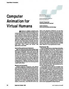
The virtual tennis players animated by real-time motion capture with the “live” player in Geneva and the player in Lausanne shown inset.
15 Networked environment with autonomous referee.
(a)
the body, hands, and face. As mentioned, the BodyBuilder program models the body surface. These surface contours are associated with the skeleton segments and joints. The skeleton serves as a support in generating motion. For hand creation, designers can modify a default template hand to build a specific hand. The default hands are associated with the skeleton to provide postures used for real-time animation. Both local and global transformations take place in the sculptor program. Similarly, the face generally starts from a generic model that includes the structure information provided by definition of regions. Modifications of the face, however, are done to retain the structure. A method for automatic face reconstruction uses two orthogonal views of pictures as the starting point.24 Deformations are performed separately on different entities (body, hands, and face) based on the model used for each part. Choosing a different model for each entity is motivated by the particular animation requirements of each entity in real time. Different entities are assembled into a single skin envelope using the Dody (deformable body) library. Handling and managing each entity’s deformations also takes place in the Dody library. Motion control generates and controls the movements for different entities. For motion control, we separated the body and face, but included the hands in the body because they’re also skeleton based. You can generate the skeletal motion using the interactive software program Track, in which some predefined actions can also be combined. A motion capture module is also available for real-time motion capture of the body. Similarly, you can generate facial movements in terms of expressions or phonemes in an interactive Face program. Direct motion capture from a real face is also possible. For ani-
(b)
mation, the body motion (in terms of angular values of joints) and face motion (in terms of MPAs) pass to the Dody library for appropriate deformations. In a higher level motion library,10 you design motion as a set of actions for the different entities. You can then blend and simultaneously apply these actions. This library offers a high-level programming environment suitable for real-time applications.
Two case studies We have applied these tools and techniques to CyberTennis and CyberDance to explore their application to real-time simulations.
CyberTennis At the opening session of Telecom Interactive 97 in Geneva, Switzerland, we presented in real time a virtual, networked, interactive tennis game simulation. This demonstration posed a big challenge because, for the first time, we had to put together several different computer-related technologies and corresponding software. It had to work in real time at a specific moment on an exposition site without permanent installations. In this demonstration the interactive players were merged into the VE as shown in Figure 14, by headmounted displays, magnetic flock of bird sensors, and data gloves. The University of Geneva player appeared “live” on stage at the opening session, and the other player took part from the EPFL Computer Graphics Lab at Lausanne, approximately 60 kilometers distant. To manage and control the shared networked VE, we used the Virtual Life Network, a general-purpose clientserver network system using realistic virtual humans (avatars) to represent users. In Figure 15a, a camera view displays, in real time, the network environment
IEEE Computer Graphics and Applications
53
. Animating Virtual Humans
16 Motion capture for realtime dancing animation of a virtual clone.
and the avatars. These avatars support body deformation during motion. They also represent autonomous virtual actors, such as the autonomous referee shown in Figure 15b as part of the tennis game simulation. A special tennis ball driver animated the virtual ball by detecting and computing collisions between the tennis ball, the virtual rackets, the court, and the net. We employed the following hardware: ■ At the Geneva site, two SGI Onyx 2 systems for the
first player client and the Referee client, both connected to one Impact over local Ethernet. The Impact contained one ATM card and served as a router for fast communication with Lausanne. The VR devices included an Ascension MotionStar with 14 sensors, one Virtual Research VR4 HMD, two Virtual Technologies Cybergloves, and one Spaceball Technologies Spaceball to drive the virtual video camera. ■ At the Lausanne site, one Onyx for the second player client and two Impacts for the Referee client and the VLNet server. These three machines used ATM cards to communicate with the server. The VR devices were identical to those used at Geneva except for the magnetic sensors: a set of 16 Ascension Technology Flock of Birds (only 14 were used in the motion capture process).
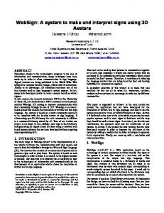
17 Professional dancers and three virtual actors dancing simultaneously.
CyberDance
54
September/October 1998
CyberDance—a new kind of live performance— provides interaction between real professional dancers
on stage and virtual ones in a computer-generated world. This demonstration used our latest development in virtual human representation (real-time deformation) together with the latest equipment in VR (for motion tracking). Our first performance, created for the Computer Animation film festival in Geneva September 1997, was an 18-minute show with eight professional dancers and giant screens for computer-generated images. Since then, we have performed at the Creativity Institute at Zermatt and at another site in Geneva. The show, which represented the creation of the “second world,” consisted of three parts. In the first part, the virtual world re-created the planet earth in the universe, and the choreography reflected the evolution of different styles of music through time. In the second part, virtual humans appeared in the virtual world and one real dancer was tracked to animate his virtual clone in real time, represented by a fantasy robot. Figure 16 shows snapshots of the live performance using motion capture. We can see the dancer tracked on stage, while the result of this tracking went to construct the virtual robot displayed in real time. The audience could see both the real and the virtual dancers simultaneously. In the third part, the virtual actors danced to a given choreography. Figure 17 shows the three virtual dancers following the choreography recorded using a motioncapture device. The same choreography was used for the three clones sharing the VE.
.
Conclusion Our real-time characters may assume any position and work well for interactive TV applications, simulation, and shared VEs. They don’t need to be completely predefined, as in most current video games. On the other hand, they take only a small amount of time to render, unlike in films, where most calculations occur offline. Further research includes elaborating on a user-interface for real-time simulation and improving the simulated individuals’ visual quality. Increasing realism requires revising and improving our methods, although the results should not differ much qualitatively. We’re working on the real-time simulation of hair and deformable clothing, and on a variety of autonomous behaviors. With the goal of accelerating the cloning process, we’re also making progress on the automatic 3D reconstruction and simulation of virtual faces. ■
Acknowledgments Thanks go to Jean Claude Moussaly, Marlene Poizat, Laurence Suhner, and Nabil Sidi Yacoub from Miralab, who designed the virtual humans and the CyberDance environment. Patrick Keller from LIG designed the virtual tennis environment. We’re also grateful to Chris Joslin for proofreading this document and for the reviewers comments. This research is funded by the Swiss Priority Program (SPP), the Swiss National Science Foundation, and the Electronic Arenas for Culture, Performance, Art, and Entertainment (Erena) European project for the CyberDance project.
References 1. N. Magnenat-Thalmann and D. Thalmann, “Digital Actors for Interactive Television,” Proc. IEEE, Special Issue on Digital Television, Part 2, July 1995, pp.1022-1031. 2. M. Slater and M. Usoh, “Body-Centered Interaction in Immersive Virtual Environments,” Artificial Life and Virtual Reality, N. Magnenat-Thalmann and D. Thalmann, eds., J.Wiley, Chichester, UK, 1994, pp.1-10. 3. K. Perlin and A. Goldberg, “Improv: A System for Scripting Interactive Actors in Virtual Worlds,” Proc. Siggraph 96, ACM Press, New York, 1996, pp. 205-216. 4. N. Magnenat-Thalmann and P. Kalra, “The Simulation of a Virtual TV Presentor,” Proc. Pacific Graphics 95, World Scientific, Singapore, 1995, pp. 9-21. 5. J. Shen and D. Thalmann, “Interactive Shape Design Using Metaballs and Splines,” Proc. Implicit Surfaces 1995, M.P. Gascule and B. Wyvill, eds., Eurographics Assoc., Grenoble, France, 1995, pp. 187-196. 6. G. Sannier and N. Magnenat-Thalmann, “A User-Friendly Texture-Fitting Methodology for Virtual Humans,” Proc. Computer Graphics Int’l 97, IEEE CS Press, Los Alamitos, Calif., 1997, pp. 167-176. 7. R. Boulic et al., “The Humanoid Environment for Interactive Animation of Multiple Deformable Human Characters,” Proc. Eurographics 95, Blackwell Publishers, England, Aug. 1995, pp. 337-348.
8. T. Capin et al., “Virtual Human Representation and Communication in the VLNet Networked Virtual Environments,” IEEE CG&A, Vol. 17, No. 2, 1997, pp. 42-53. 9. T. Molet, R. Boulic, and D. Thalmann, “A Real-Time Anatomical Converter for Human Motion Capture,” Proc. Eurographics Workshop on Computer Animation and Simulation 96, R. Boulic and G. Hégron, eds., Springer-Verlag, Vienna, 1996, pp. 79-94. 10. H. Noser and D. Thalmann, “Synthetic Vision and Audition for Digital Actors,” Proc. Eurographics 95, Blackwell Publishers, England, Aug. 1995, pp. 325-336. 11. T.A. Funkhauser and C.H. Sequin, “Adaptative Display Algorithm for Interactive Frame Rates During Visualization of Complex Virtual Environments,” Proc. Siggraph 93, ACM Press, New York, 1993, pp. 247-254. 12. Hand Gestures for HCI, technical report, Hand Centered Studies of Human Movement Project, School of Kinesiology, Simon Fraser University, Vancouver, 1996, http://fas.sfu.ca/cs/people/ResearchStaff/amulder/personal/vmi/HCI-gestures.htm. 13. L. Moccozet and N. Magnenat-Thalmann, “Dirichlet FreeForm Deformations and their Application to Hand Simulation,” Proc. Computer Animation 97, IEEE CS Press, Los Alamitos, Calif., 1997, pp. 93-102. 14. J.E. Chadwick, D. Hauman, and R.E. Parent, “Layered Construction for Deformable Animated Characters,” Proc. Siggraph 89, ACM Press, New York, 1989, pp. 243-252. 15. H. Delingette, Y. Watanabe, and Y. Suenaga, “Simplex Based Animation,” Proc. Computer Animation 93, N. Magnenat-Thalmann and D. Thalmann, eds., Springer Verlag, Berlin, 1993, pp. 13-28. 16. T.W. Sederberg and S.R. Parry, “Free-Form Deformation of Solid Geometric Models,” Proc. Siggraph 86, ACM Press, New York, 1986, pp. 151-160. 17. G. Farin, “Surface Over Dirichlet Tessellations,” Computer Aided Geometric Design, Vol. 7, No. 1-4, North-Holland, 1990, pp. 281-292. 18. L. Moccozet, Hands Modeling and Animation for Virtual Humans, PhD thesis report, Miralab, University of Geneva, 1996. 19. P. Kalra et al., “Simulation of Facial Muscle Actions Based on Rational Free-Form Deformations,” Computer Graphics Forum, Vol. 2, No. 3, 1992, pp. 65-69. 20. P. Ekman and W.V. Friesen, Manual for the Facial Action Coding System, Consulting Psychology Press, Palo Alto, Calif., 1978. 21. N. Magnenat-Thalmann, P. Kalra, and I.S. Pandzic, “Direct Face-to-Face Communication Between Real and Virtual Humans, Int’l J. of Information Technology, Vol. 1, No. 2, 1995, pp. 145-157. 22. Abbot (Demo), Speech Recognition System, Cambridge, UK, http://svr-www.eng.cam.ac.uk/~ajr/abbot.html. 23. Festival Speech Synthesis System, University of Edinburgh, UK, http://www.cstr.ed.ac.uk/projects/festival.html. 24. W.S. Lee, P. Kalra, and N. Magnenat-Thalmann, “ModelBased Face Reconstruction for Animation,” Proc. Multimedia Modeling 97, World Scientific, Singapore, 1997, pp. 323-338.
IEEE Computer Graphics and Applications
55
. Animating Virtual Humans
Amaury Aubel is a PhD candidate in the computer graphics lab at the Swiss Federal Institute of Technology (Ecole Polytechnique Fédéral de Lausanne—EPFL). His research interests include geometric deformations for human animation and human crowd rendering. Part of his work takes place in the framework of the European project Platform for Animation and Virtual Reality (PAVR). He received a software engineering diploma from the Computer Science Institute in Paris (Institut d’Informatique d’Entreprise) in 1995.
Prem Kalra is currently an assistant professor at the Indian Institute of Technology (IIT), Delhi. He worked at Miralab from 1990 to 1997 as research assistant and then as assistant professor. His research interests include geometric modeling and deformation, image-based animation, virtual human simulation, and virtual reality. He obtained his PhD in computer science from the Swiss Federal Institute of Technology (Ecole Polytechnique Fédéral de Lausanne—EPFL), Lausanne in 1993.
Nadia Magnenat-Thalmann has researched virtual humans for more than 20 years. She studied psychology, biology, and chemistry at the University of Geneva and obtained her PhD in computer science (cum laude) in l977. In l989 she founded Miralab, an interdisciplinary creative research laboratory at the University of Geneva. Some recent awards for her work include the l992 Moebius Prize for the best multimedia system awarded by the European Community, “Best Paper” at the British Computer Graphics Society congress in l993, to the Brussels Film Academy for her work in virtual worlds in 1993, and election to the Swiss Academy of Technical Sciences in l997. She is president of the Computer Graphics Society and chair of the IFIP Working Group 5.10 in computer graphics and virtual worlds.
56
September/October 1998
Laurent Moccozet is a senior researcher at Miralab, at the Computer Science Center, Universitiy of Geneva. His main research interests are shape modeling, geometric deformation and their applications to virtual humans, and virtual worlds. He received a PhD in information systems from the University of Geneva in 1996.
Gael Sannier is a research assistant at the University of Geneva at Miralab. His main interests are in user-friendly texture-fitting methods and virtual presenter for TV applications. He studied at the University Lyon-2 in Lyon and earned an MS in computer graphics in 1996.
Daniel Thalmann researches realtime virtual humans in virtual reality, networked virtual environments, artificial life, and multimedia at the Swiss Federal Institute of Technology (Ecole Polytechnique Fédéral de Lausanne—EPFL). He received a diploma in nuclear physics in 1970, a certificate in statistics and computer science in 1972, and a PhD in computer science (cum laude) in 1977 from the University of Geneva. He is coeditor-in-chief of the Journal of Visualization and Computer Animation, member of the editorial board of The Visual Computer, CADDM Journal (China Engineering Society), and Computer Graphics (Russia). He is co-chair of the Eurographics Working Group on Computer Simulation and Animation and member of the executive board of the Computer Graphics Society. Readers may contact Magnenat-Thalmann at Miralab, University of Geneva, 24 Rue du General Dufour, CH 12111 Geneve 4, Switzerland, e-mail nadia.thalmann@ cui.unige.ch.
.
Multiresolution Representation of 3D Geometry for Progressive Transmission Workshop at IEEE Visualization 98
Distributed Visualization Systems Workshop at IEEE Visualization 98
17 October 1998 1:00 pm to 5:00 pm
Distributed visualization systems have been studied since the beginning of the computer graphics adventure and widely implemented and used. The evolution of computing technologies, especially in the Internet context, has changed the way we design and implement such systems. The spectrum of potential users has been greatly enlarged, and new types of services are needed to allow access to remote services and to support remote collaborative work and concurrent engineering. This full-day workshop will gather a group of people with different backgrounds and interests to share and consolidate their various experiences in the field of remotely accessing distributed data through visual interfaces, including CSCW, distributed VR, and database issues. We plan to discuss the following three topics: applications of distributed visualization, environments and user interfaces, and technologies for distributed visualization. For more information contact Michel Grave (
[email protected]) or Wilfrid Lefer (
[email protected]).
Recently there’s been considerable interest in methods for progressively representing 3D surface geometry in compressed form and progressively delivering it across a network or to a display terminal. A few techniques have been proposed in the past few years that can be broadly classified as methods based on polygonal surfaces or wavelets. Now’s a particularly good time to discuss these issues because of the current interest in visualization of large data sets, especially geographic data sets. Also, there’s considerable activity in the standardization of such techniques (for example, VRML and MPEG). This workshop will bring together experts in approaches using polygonal surfaces as well as using wavelets for visualization problems involving large geometric databases where the issue of progressive transmission of display is important. For more information, contact André Gueziec (
[email protected]) or Gabriel Taubin (
[email protected]).
17 October 1998 8:00 am to 5:00 pm
[email protected]
FREE! All IEEE Computer Society members can obtain a free, portable email
[email protected]. Select your own user name and initiate your account. The address you choose is yours for as long as you are a member. If you change jobs or Internet service providers, just update your information with us, and the society automatically forwards all your mail.
Sign up today at
Go to the
Online Catalog http://computer.org and order using the online shopping cart and the secure order form
IEEE Computer Society 10662 Los Vaqueros Circle
http://computer.org
Los Alamitos, CA 90720-1314 Toll-Free +1 800.CS.BOOKS Phone: +1 714.821.8380