{halupka@eecg, rabi@ecf, parham@ecf, ali@eecg}.toronto.edu. ABSTRACT ..... Software development was done in Motorola. ® ... An FPGA or a fully custom.
REAL-TIME DUAL-MICROPHONE SPEECH ENHANCEMENT USING FIELD PROGRAMMABLE GATE ARRAYS David Halupka, Seyed Alireza Rabi, Parham Aarabi, and Ali Sheikholeslami The Edward S. Rogers Sr. Department of Electrical and Computer Engineering University of Toronto, Canada {halupka@eecg, rabi@ecf, parham@ecf, ali@eecg}.toronto.edu ABSTRACT This paper discusses an implementation of a dualmicrophone phase-based speech enhancement technique. By using the phases of the incoming sound signals, we mask frequencies with low signal-to-noise ratio (SNR) between the two microphones. Phase-based filtering can achieve high SNR gains with just two microphones, making it ideal for hand-held devices. However, these devices have a limited battery life and lack the processing power needed for a software based implementation. This paper presents a field programmable gate array (FPGA) implementation that was designed specifically for low-power operation. The FPGA based implementation is compared, with respect to processing capabilities and power utilization, with an offthe-shelf low-power digital signal processor (DSP) implementation. 1. INTRODUCTION The fact that speech recognition systems do not work effectively in practical environments where noise, background or irrelevant conversations, are present has fueled research interest in the areas of speech enhancement and speech separation [1–3]. Microphone array-based speech processing techniques, in particular, have received much research interest because of the potential for significant noise removal. Various microphone array-based speech enhancement techniques have been proposed, including beamforming, superdirective beamforming, postfiltering, and phase-based filtering. Of these techniques, dual-microphone phasebased filtering, also known as time-frequency masking (TFM), has shown a great deal of promise, achieving recognition gains of 28.9% over the single channel noisy signal, 22.0% over superdirective beamforming, and 8.5% over post filtering [2] for the case of two speakers in a reverberant environment (reverberation time = 0.1 s). TFM, like other non-blind array based speech enhancement techniques, requires the location of the speaker of interest, which can be estimated by calculating the time delay
of arrival (TDOA) between the microphone pair [4]. As such, TFM is very computationally intensive. For example, a 1.1 GHz Intel Pentium IIIr processor is needed to perform dual-microphone TFM masking and TDOA estimation in real-time for a 20 kHz audio stream. Hand-held devices, which would benefit most from speech recognition, do not have the equivalent processing power of a Pentium IIIr processor. Users will also not accept speech recognition systems that will significantly reduce the battery life of their device, no matter how convenient and robust to noise this system might be. There is a definite need for power efficient implementations of speech enhancement and speech recognition algorithms. This paper presents an FPGA implementation of TFM specifically designed for low-power consumption. This implementation is compared to an off-the-shelf DSP implementation, based on FreescaleTM Semiconductor’s DSP56858 16-bit DSP. Section 2 of this paper gives a brief overview of TFM. Section 3 describes two power-saving optimizations utilized to reduce the FPGA power consumption. Section 4 outlines the DSP based implementation. Results comparing these two implementations are given in section 5. 2. TIME-FREQUENCY MASKING Assume that two microphones are placed in the vicinity of a sound source. Two signal segments of a short duration are obtained by windowing each microphone signal by a Hanning window. In the frequency domain, these two short microphone signals can be modeled as, M1,k (ω) = Sk (ω) + N1,k (ω) M2,k (ω) = Sk (ω)e
−jωτ
+ N2,k (ω)
(1a) (1b)
where for time segment k, Sk (ω) is the signal arriving from the signal source of interest, having a TDOA of τ between the microphone pair, and N1,k (ω) and N2,k (ω) model the environmental and microphone noises. Sk (ω) is the timefrequency representation of the time-domain signal s(t).
Under ideal conditions, i.e. no noise and reverberations, the time-frequency segments M1,k (ω) and M2,k (ω) will be related by, θk (ω) = ∠M1,k (ω) − ∠M2,k (ω) − τ ω = 0
(2)
where ∠ denotes the phase angle of its argument. However, in noisy and/or reverberant environments θk (ω), the phase error, does not equal zero. Work by [2] showed that θk (ω) is in fact related to the amount of noise and reverberations corrupting the desired signal Sk (ω). In a noisy and reverberant environment, θk (ω) can be directly calculated, provided the position of the speaker to be isolated (τ ) is known. As proposed by [1], a timefrequency filter can be constructed based on θk (ω), ψk (ω) =
1 1 + γθk2 (ω)
Yk (ω) = ψk (ω)M1,k (ω)
(3a) (3b)
where it is assumed that θk (ω) is wrapped to be in the range [−π, π]. The term γ is an adjustable parameter which controls the aggressiveness of the filter; in low SNR conditions a high value of γ is favorable, whereas in high SNR conditions a low value of γ is favorable as a high value of γ will actually corrupt the signal of interest. [1, 2] Conversion of Yk (ω), the filtered signal, to y(t) is performed by taking the inverse Fourier transform of all k segments, half-overlapping the segments, and adding the overlapped samples together.
half-overlapped and summed with the previously processed data. 3.1. TDOA Estimation Optimizations The PHAT TDOA search, described by Eq. 4, is an exhaustive search, and is the most computationally expensive calculation performed on the chip. For a search window of -32 to 32 samples at a resolution of 0.125 samples, approximately 130,000 evaluation of the cosine function have to be performed. There are three major methods of evaluating trigonometric functions in hardware: using the CORDIC algorithm, Taylor expansion, or parametric curve fitting. However, none of these methods are power efficient. Z τ˜ = max arg
cos (∠M1,k (ω) − ∠M2,k (ω) − βω) dω
β
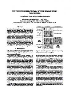
(4) Work by [7] showed that the PHAT cosine can be approximated by a rectangular function without a significant reduction in TDOA estimation accuracy. In this work, various quantizations (approximations) to the cosine function were studied, a sample of which are shown in Fig. 1. Table 1 shows the relative required average power to perform TDOA estimation using different approximations. Power estimates are given for a custom digital 0.18 µm CMOS process provided by TSMC using Synopsisr design tools. 1
1
0
0
3. FPGA IMPLEMENTATION −1 −3
To provide TDOA estimates, a phase-transform (PHAT) [4] sound localization algorithm is incorporated into the FPGA. An Alterar Stratixr EP1S40 FPGA housed on a Microtronixr development kit is utilized as the target device. The FPGA system runs on a 6 MHz clock. Analog to digital conversion is provided by two 8-bit National Semiconductor ADC08831 sampling at a rate of 20 kHz. A 1024-sample (51.2 ms) window is processed at a time, which is offset by 512 samples with respect to the previously processed window. Each 1024-sample window is multiplied by a Hanning window. An integer fast Fourier transform (FFT) [5] algorithm is used to perform an invertible discrete Fourier transform. The conjugate symmetry of real signals is used to perform the FFT of two real signals using only one FFT operation. Cartesian to Polar conversion is performed by the CORDIC algorithm [6]. The phases of each frequency component are used to estimate the TDOA, as well as for calculation of the TFM mask. The mask is applied to each channel, and the two channels are then beamformed. After performing the inverse FFT on the beamformed data, the processed data is
−2
−1
0
1
2
3
−1 −3
(a) Rectangular 1
0
0
−2
−1
0
1
(c) 7 Level Cosine
−1
0
1
2
3
2
3
(b) 3 Level Cosine
1
−1 −3
−2
2
3
−1 −3
−2
−1
0
1
(d) 15 Level Cosine
Fig. 1. Non-linear functions Table 1. TDOA power consumption Function Power Utilization Ideal Cosine 10.6 mW 180 µW Rectangular 3 Level Cosine 213 µW 247 µW 7 Level Cosine 15 Level Cosine 285 µW Performance of each function was measured by localizing a human speaker in a noisy and reverberant environment.
Approximately 60 s of speech was used for these tests, the speaker was arranged in 4 different positions about the microphone pair in a semi-circular arc. Another speaker, the noise source, was placed approximately directly in front of the array. Localization performance was measured over four different SNR conditions. Table 2 summarizes the performance of the localizations in terms of percentage of estimates that were off by more than ±2 samples from the expected value. Table 2. Percentage of abnormal TDOA estimates SNR Function 0 dB 3 dB 6 dB 12 dB Ideal Cosine 61.9% 53.4% 46.7% 40.3% Rectangular 71.9% 65.9% 60.9% 55.6% 3 Level Cosine 67.2% 59.0% 52.4% 45.2% 7 Level Cosine 62.1% 53.4% 46.7% 40.3% 15 Level Cosine 61.9% 53.6% 46.7% 40.2% The 7 level cosine approximation is used in this FPGA implementation, as this function yields the best localization accuracy for the amount of power dissipated. 3.2. TFM Optimizations Time frequency masking along with beamforming is a straightforward operation. However, division is an expensive operation to implement in hardware, especially when it comes to fixed-point operations, as a 32-bit by 16-bit divider is necessary to perform fixed-point division. The FPGA performs TFM without the use of division. The estimate for each microphone’s phase will, unavoidably, have some degree of error. This error is a result of windowing a continuous signal and the limited numerical precision used to process the signal of interest. Thus a curve which approximates the TFM function can be used to perform phase-based speech separation, instead of using Eq. 3b. Through experiments, qualitative listening and quantitative experiments that used Microsoft’s speech recognition engine, it was discovered that a step approximation ( 0.05 rad steps) to the TFM masking yields good separation results. Table 3 shows speech recognition results from a speaker, mixed with speech noise at four different SNRs, and filtered using Eq. 3b and using a step approximation to the TFM curve. Approximately three minutes of speech was used, containing 487 words. The training data set was used to conduct these recognition experiments. The step function can be easily stored in a look up table, due to quantization of θk (ω). However, multiplication is still required to multiply the magnitudes of each microphone channel. To further minimize power consumption, multiplication has been replaced by right shifts and addi-
Table 3. Word error rates for a speaker in a noisy and reverberant environment using Microsoft’s speech recognition engine (γ=5) Unprocessed Ideal TFM Step TFM SNR No noise 1.44% 20 dB 6.37% 3.29% 3.59% 10 dB 25.46% 5.85% 5.13% 0 dB 63.45% 23.48% 22.18% -10 dB 88.09% 68.00% 66.39% tion. Each step of the curve consists of 4 parameters. As depicted by Eq. 5, the first parameter describes the magnitude of the initial right shift (0:15), and the remaining three parameters (0,1) select the number of additional right shift operations: the results of all shift operations are summed. ³ p2 p3 p4 ´ Yk (ω) = M1,k (ω)2−p1 1 + + + (5) 2 4 8 4. DSP IMPLEMENTATION In order to show the validity of the FPGA implementation, in terms of performance and power efficiency, TFM masking was also implemented on a commercially available low-power DSP evaluation platform. The implementation was based on Freescaler Semiconductor’s DSP56858 DSP. Software development was done in Motorolar ’s Code Warrior. Code was developed to have minimal execution time (instruction count), while secondarily minimizing power utilized by memory traffic. To minimize execution time, factory developed functions supplied by Code Warrior for the DSP56858 were utilized wherever possible. All code written for this project was developed in ANSI C. On the DSP, each trigonometric calculation takes approximately 300 instructions, therefore a cosine based PHAT TDOA estimation technique will not be able to run in realtime on the 120 MHz DSP. A rectangular function [7] is the only function that was able to yield real-time TDOA estimates. However, the 120 MHz DSP was only capable of performing real-time TDOA estimation and TFM on two 8 kHz sampled audio streams processed in 256 sample windows. In fact, for real-time operation, TDOA estimation was restricted to ±3.375 samples, with a step size of 0.125 samples. Real-time TFM processing of two 12 kHz sampled audio signals is also possible, by completely disabling TDOA estimation. 5. RESULTS The benefits of TFM as compared to other speech enhancement techniques has been shown in previous work [2] for both synthetic and realistic environments. Thus, the results in this section will compare the performance of a
floating point MatLabr implementation to the FPGA and DSP implementation in terms of post-processing SNR. Two speakers were used for the following test case: the speaker of interest was placed directly in front of the microphone pair and the noise source was delayed by 0.5 ms with respect to the microphone pair. Three minute speech segments from the speaker of interest and the noise source were mixed synthetically in MatLabr at 6 different SNRs. In order to avoid the biasing introduced by microphones, analog amplifiers, and sampling circuitry, as well as digital to analog conversion on the real performance of the algorithm implemented, all data was written and read from the FPGA and DSP digitally. Table 4. Post-processing SNR (γ=5) [8] SNR MatLab FPGA DSP -6 dB 2.7736 dB 3.8982 dB 4.2516 dB -3 dB 5.4868 dB 6.5940 dB 6.1954 dB 0 dB 8.1176 dB 9.1743 dB 7.9948 dB 3 dB 10.5982 dB 11.5625 dB 9.7055 dB 6 dB 13.0443 dB 13.7103 dB 11.3574 dB 12 dB 17.6291 dB 16.8008 dB 14.3473 dB Power consumption for the FPGA and DSP implementation was measured using two metrics, since the FPGA and DSP are housed on evaluation boards. Power consumptions for the processing cores and the incremental power used by each evaluation board are given in Table 1. Incremental power consumption is measured as the difference between power utilized when the board is in reset and when performing TFM. The memory used by the DSP is housed off chip on the evaluation board, and as such, external power consumption of the memory should be counted towards the power utilized by the DSP implementation. Table 5. Power utilization FPGA DSP Core 68.55 mW 79.92 mW Incremental 183.6 mW 650 mW Although the DSP implementation offers a quick method to demonstrate the functionality of TFM, it is not a viable platform for a speech enhancement system. A fully viable speech enhancement system needs a method of estimating TDOAs. Then, perhaps with user feedback, these TDOA estimates can be used to enhance the signal from the speaker of interest. The 120 MHz DSP56858 used is underpowered, and cannot provide real-time TDOA estimates. For real-time low-power performance, a hardware platform is the most viable option. An FPGA or a fully custom application specific integrated chip implementation is capable of providing real-time performance with controllable power consumption. The Verilog code implemented on the
Stratix FPGA only uses 10% of available logic capacity. Moreover, this code was originally developed for a fully custom 0.18 µm CMOS silicon solution, which is capable of real-time speech separation using only an estimated 3.44 mW of power. 6. CONCLUSION Two hardware-based implementations of TFM were discussed in this paper. It was shown that, although realtime TFM operation is possible using both the FPGA and DSP implementations discussed, the 120 MHz DSP implementation is severely underpowered in terms of computational capacity to yield real-time TFM speech separation and TDOA estimates. Moreover, the DSP implementation utilizes 3.5 times the power of the FPGA implementation, but does not provide the same functionality as the FPGA implementation. 7. REFERENCES [1] G. Shi and P. Aarabi, “Robust digit recognition using phase-dependent time-frequency masking,” in Proceedings of ICASSP, Hong Kong, Apr. 2003, pp. 684–687. [2] P. Aarabi and G. Shi, “Phase-based dual-microphone robust speech enhancement,” IEEE Transactions on Systems, Man, and Cybernetics, vol. 34, no. 4, pp. 1763–1773, Aug. 2004. [3] C. Lai and P. Aarabi, “Multiple-microphone timevarying filters for robust speech recognition,” in ICASSP, Montreal, Canada, May 2004. [4] M. Brandstein and H. Silverman, “A robust method for speech signal time-delay estimation in reverberant rooms,” in Proceedings of ICASSP, May 1997, pp. 375– 378. [5] S. Oraintara, Y.-J. Chen, and T. Nguyen, “Interger fast fourier transform (INTFFT),” IEEE Transactions on Signal Processing, vol. 50, no. 3, pp. 607–618, Mar. 2002. [6] J. Volder, “The CORDIC trigonometric computing technique,” IRE Transactions on Electronic Computers, vol. EC-8, no. 3, pp. 330–334, Sept. 1959. [7] P. Aarabi and S. Mavadadi, “Multi-source time delays of arrival estimation using conditional time-frequency histograms,” Information Fusion, vol. 4, no. 2, pp. 111– 122, June 2003. [8] (2004, Aug.) Clips of TFM pre- & post-processed audio samples. [Online]. Available: http://www.apl. toronto.edu/projects/fpgatfm.html