For example, in the retail case, when the sale of a product within an hour crosses a ..... L.company = âHPâ is not a valid condition for composite EI o1 e, because.
Real-Time Event Handling in an RFID Middleware System Kaushik Dutta1 , Krithi Ramamritham2, B. Karthik2 , and Kamlesh Laddhad2 1
College of Business, Florida International University, Miami, FL 2 Indian Institute of Technology Bombay, Mumbai, India
Abstract. Radio Frequency IDentification (RFID) tags have emerged as a key technology for real-time asset tracking. Wide application of RFID leads to huge amounts of data being generated from scan of each of these RFID tags on individual items, for example, the RFID system of a moderate size retail chain will generate 300 million RFID scans per day. Extracting meaningful information out of this huge amount of scan data is a challenging task. Moreover CIOs are looking for real time business decision from this RFID scan data. In this paper we show how to add value to an RFID middleware system by enabling it to handle a large number of RFID scan data and execute business rules in real-time. Experimentally we demonstrate that our proposed approach is very time efficient compare to a similar implementation with existing technologies. Lastly we also propose an architecture for a distributed RFID middleware system to handle raw RFID scan data.
1 Introduction RFID is an automated identification technology that allows for non-contact reading of data [1], making it attractive in verticals such as manufacturing, warehousing, retail [2, 3], logistics, pharmaceutical [4], health care [5] and security. RFID systems are foreseen as replacement to the legacy bar code system of identifying an item. One of the major advantages of RFIDs over bar codes is that it is a non-line-of-sight technology thus every item need not be handled manually for reading. In addition, RFID readers can read tags even when they are hidden. However, wide application of RFIDs leads to huge amounts of data being generated from the scan of these RFID tags on individual items; extracting meaningful information out of this huge amount of scan data is a challenging task. Moreover, today’s CIOs are looking for real time business decisions based on RFID scan data. For example, in the retail case, when the sale of a product within an hour crosses a threshold, to avoid out of stock situations, a store manager may want more products be ordered for the inventory. In a hospital, when the drug to be given to a patient is considered along with the particulars of an ‘RFID tagged’ patient, the doctor or the nurse can be informed of drug interactions with the drugs the patient is currently taking. Once RFID tags are scanned and subsequently analyzed at the back-end, such decisions are definitely possible in today’s technology. However with RFID technology, users want real-time information to take a decision on the spot, e.g. users of an online e-commerce site may want to know, in real-time, details of what stage of production an on-demand produced item is. S. Bhalla (Ed.): DNIS 2007, LNCS 4777, pp. 232–251, 2007. c Springer-Verlag Berlin Heidelberg 2007 �
Real-Time Event Handling in an RFID Middleware System
233
In this paper we develop and present the architecture of a system that will allow businesses to take real-time decisions on the basis of huge amounts of data generated by the RFID scans. To further motivate our work in the next section we briefly describe a case study on the deployment of RFID technology in supply chain scenarios from Harvard Business Case studies [6] and explain how our research can help in this scenario. 1.1 A Motivating Scenanio Consider a Supermarket; Metro Group (MG). Let us assume supply to MG follows this route: Manufacturers make pallets containing cases of same products and send them to distribution centers (DC). At the DC, these pallets are reassembled into mixed pallets and then sent to different stores of MG. Pallets arrive at stores in accordance with the need specified by that store. Similarly, the pallets arrive at the DC in accordance with the requirement from the DC. Using bar codes, mistakes happen while counting the number of pallets loaded on to a truck at the manufacturer’s site or the kinds of cases transferred to the mixed pallet at the DC. All these result in slowing down the process, revenue loss or out of stock position at the stores [6]. To overcome such problems, pallet-level and case-level RFID tagging is used. The pallets leaving the manufacturer’s site are tagged. They are loaded on to the truck and the RFID reader counts the number of pallets being loaded. At the DC, pallets are reassembled into mixed pallets. This can be automated with the help of RFID tags. Thus, mistakes in packing the cases into the right pallets, will be reduced. Reassembled pallets are now sent to the stores. These pallets are received at the backroom of the store and are opened and verified for correct configuration using RFID readers. The cases are kept at the backroom before replenishing the shelf when the store closes. When the number of items at the shelf for a certain product falls below a threshold, it is refilled from the backroom. This must be done in an automated way. The employees may not always remember the number of items remaining on each shelf. Thus, an indicator might inform the backroom to refill a certain item as its number falls below the threshold. Also, keeping excess stocks of all items in the backroom is not advisable. Thus, ordering for new stocks should happen if the number of cases of that product in the backroom is below a threshold. All these processes could not be efficiently handled by human beings. At the shelf, sensors can be monitoring the conditions (e.g., temperature for food items). Alarms can be raised if conditions worsen for a certain item. Items which are about to expire can be identified for an extra discount. These can be automated as the RFID tags may contain the item’s expiry date. RFID Enabled Tasks. In this paper we develop an event based RFID system that will enable us to observe and detect the state of the system and take actions accordingly in real-time. Our proposed approach will enable the RFID middleware system of MG to address the following business rules. 1. If the number of items on a shelf goes below a threshold, send an alert to the backroom. 2. If the number of items in the backroom is below a threshold, send an alert to the store manager, or ask DC to send the item.
234
K. Dutta et al.
3. If the DC is out of stock for an item, a request for a new supply for the item should be sent to the manufacturer. 4. If the DC has already dispatched the item in the last consignment to the store, recognize this and alert the store manager. 5. If the temperature of a food item is being monitored by a sensor and it observes abnormal temperature variations such that the item placed in that shelf can not be kept in such situations, alert the concerned authority about this problem. 6. If a certain food item kept on a shelf is about to expire, make visual announcements that the cost has been reduced. Challenges in Exploiting RFID. Full utilization of the RFID system deployed in MG will occur only when these events (e.g., number of items on a shelf going below a threshold) can be detected and respective action (e.g., send an alert to the backroom) be taken in the least possible time. Some of the key challenges in developing such a system are, (i) The number of RFID events is huge. Every scan by RFID scanner generates an event, leading to large number of such events from which identifying a particular event (e.g., number of items on a shelf goes below a threshold) is a challenging task. Following the example given in [7] (which is also very much applicable in MG case), suppose the retailer with 3,000 stores sells 10,000 items a day per store. Assume that we record each item movement with a tuple of the form: (EPC, location, time), where EPC is an Electronic Product Code which uniquely identifies each item. If each item leaves only 10 traces before leaving the store by going through different locations, this application will generate at least 300 million tuples per day. Extracting meaningful information from this 300 million tuples is the challenge. (ii) The event should be detected in the least time possible for real time business decisions to be taken. The time difference between a shelf becoming almost empty and the time by which the shelf is replenished from the backroom should be as small as possible. So, nightly or periodic batch processing of such huge number of data will not serve the purpose. The problem is more complex when the RFID system is distributed, where both generation of events and detection of events happen in various systems distributed geographically at various locations. In the next section we describe the related work. In Section 3, we develop the event based model for RFID system. In Section 4, we describe the detailed architecture and approach. In Section 5 we describe an implementation of RFID event handling system using relational database. We experimentally demonstrate the performance of our system in Section 6. In Section 7 we explain how our proposed approach can be extended in a distributed system. Lastly in Section 8 we conclude the paper.
2 Related Work Recently, a number of RFID middleware systems have attracted industry attention [10, 11, 12]. The event handling mechanism in these RFID systems is very rudimentary in nature, based on Java’s event handling mechanism. In general they can handle
Real-Time Event Handling in an RFID Middleware System
235
very simple basic events e.g., raw RFID scans. They do not have any infrastructure to handle large number of complex events including events that combine RFID scans along with other environmental conditions such as temperature. In real life business scenarios, however, it is very natural to look for complex events. Developing an infrastructure to answer the questions mentioned in Section 1.1 will require elaborate system development effort in these systems and will not be efficient. Research on active database systems and event-condition-action model seems relevant to large extent. In this, some of the important work to mention are [13, 8, 14]. Because the nature of events in active databases and RFID systems is different, we can not directly apply any of the existing research, however we have borrowed several concepts from these areas to apply in our system, e.g., we borrowed the idea of indexing events on the basis of parameter values as proposed in [15]. The key differences between an RFID system and active database systems are (i) the number of events to be monitored is huge in RFID systems compared to typical active database systems (ii) the events in RFID systems are more complex in nature linking several events (including non-RFID events) together to form composite events and (iii) to achieve the desired business goal real-time response is required in RFID event handling systems. These differences make the handling of RFID events a challenging goal in it own right. With respect to research related to real-world event handling, from [9], we borrowed the idea of representing complex RFID events with the help of state diagrams. In [16, 17, 18], authors proposed pre-processing of raw RFID scan data for cleaning such as identifying missing data and detecting outliers. We show how the data-cleaning as proposed in these can be integrated with our proposed system. In [19], authors proposed a security mechanism for RFID data, which is orthogonal to the research of this paper. In essence, though we borrow some of the concepts from existing research work, so far there has not been an end-to-end solution proposed in either academics or in industry to handle large number of RFID events generated from RFID scans and hence this research.
3 Events in RFID Systems According to Wikipedia, an event is something that takes place at a particular place and time. For software systems, an event is something that needs to be monitored and may trigger a specific action. Specifying an event is therefore providing a description of the happening. Following [8], each RFID event can be described with some set of dimensions which includes source of event, event granularity, location of event, time at which the event occurred and a possible set of operations for combining events. An Event can be of primitive type or composite type. A primitive event occurs at a particular place and time. A composite event is a combination of a number of such primitive events linked by predefined operators (e.g., AND, OR, NOT etc.) [9]. In addition to this classification, in an RFID system, we define two types of events - Basic Events and Events of Interest.
236
K. Dutta et al.
3.1 Basic Events A basic event (be ) is an event generated by a source, e.g. an individual scan of RFID tag affixed to an object in the system. Following [9] and [7] a basic event(be) can be defined as a tuple (L, S, T ) where L is the label dimension containing details of the event, S is the location dimension of the event occurrence and T is the time dimension at which the event occurs. As for example, going back to our example of MG’s supply chain system, consider the following situation: An object o is being loaded on a truck in a warehouse at location s at a certain point of time t. This object gets scanned by different readers. Scan of this object by a reader attached to truck at time T = t at location S = s is a basic event generating a tuple (l, s, t). The label l will contain details of the object o such as the scanned RFID tag number of manufacturer details. In an RFID system a basic event (be ) can be generated in four ways. Object Scan: A RFID reader scans a RFID tagged object and generates the basic event, which is termed as RAW RFID event [7]. The RFID scan generates the label L and the scanner id. The location S can be derived from the RFID database [20] that contains the information about the location of the scanner corresponding to the scanner id and the time when the scan happened. The time (T ) will contain when the actual event occurs. Clock: A clock event is raised at some point in time independent of objects and other state of the system. The clock time can be absolute (e.g. 15th of August at 7:55 AM), relative (the next day after the match), or periodic (every day at 11:30 PM). The label of a clock event will just identify it as “CLOCK” event. The location (S) will remain empty in case of Clock event. External: An external event is raised by a happening outside the system, which includes environmental conditions (e.g., the temperature of the hall/room goes above 30 degrees Celsius). Typically such external events will be generated by various sensors deployed in a system e.g., temperature sensor. The label of the external event will contain sensor data e.g., temperature value in case of temperature sensor. The location will identify the location of the sensor which can be derived from a separate sensor database. The time will identify, when the sensor generated the external event. Internal: An internal event is related to internal state change of the system at time t. The internal event can be the effect of cascading action of some basic event which got fired by one of previously defined three ways. These are mostly program generated events. The label(L) of an internal event will identify the details of the event such as “Number of Items > 100” or “Average Price of item sold > 40”. The location (S) of an internal event will identify the generator i.e., the particular systems or applications that is generating this internal event. The time(T ) will denote the time at which such an event is generated. 3.2 Events of Interest (EI) Events of Interest (EI) are the events which need to be monitored. EI can be of two types (i) primitive EI and (ii) composite EI.
Real-Time Event Handling in an RFID Middleware System
237
Primitive EI. A primitive event(pe ) can be defined as a tuple (L, S, T ) where L is the label containing details of the event, S is the location of the event occurrence and T is the time at which the event occurs. However, unlike basic events, in case of primitive EIs each of this may or may not be pointedly specified. The label of a primitive EI is an indication of range of products, items or objects for which this event has been defined. This may include a particular supplier, a particular product from a particular supplier, etc. Since the EPC is a hierarchical representation of entities in supply-chain, we can use bits of EPC code to define label for primitive EI in case RFID tag contains the EPC code. The time of a primitive EI is an indication of a range of time e.g. morning 8AM10AM or today or month September. As a specific case the time of a primitive EI may be a specific time at the granularity at which it is defined in the basic event, e.g., 7.00 AM 29 Sept 2006. The location of a primitive EI is a region that may contain one or more locations at the granularity of basic events, e.g., a basic event may occur at a scanner located at the distribution center in Miami, whereas an EI may be specified as a scan in a distribution center in South Florida region which contains the distribution centers both in Miami and Tampa. For example, in the following p1e is a primitive EI. p1e = (L = {product type = #54567}, S = Shelf #583, T =� M orning � ) Here the primitive EI p1e is looking for product with “product type” as “#54567” defined in the label (L). The location (S) dimension of EI p1e is defined by the shelf number “#583”. The time (T ) is morning. Composite EI. A composite EI(oe ) is a combination of multiple primitive EIs (pe ) or multiple composite EIs linked by operators drawn from the following set [13]. AND (∧): Conjunction of two events E1 and E2 , denoted as E1 ∧ E2 , occurs when both E1 and E2 occur (the order of occurrence of E1 and E2 is irrelevant). OR (∨): Disjunction of two events E1 and E2 , denoted as E1 ∨ E2 , occurs when either E1 or E2 occurs. SEQ (⇒): Sequence of two events E1 and E2 , denoted by E1 ⇒ E2 , is when E2 occurs provided E1 has already occurred. This implies that the time of occurrence of E1 is guaranteed to be less than the time of occurrence of E2 . NOT (!): The NOT operator, denoted by !(E1 , E2 , E3 ), detects the non-occurrence of the event E2 in the closed interval formed by E1 and E3 . It is rather similar to the SEQ operator except that E2 should not occur between E1 and E3 [13]. Relative periodic (Rp ): An event E2 which occurs periodically with specified frequency after event E1 has occurred till event E3 occurs. This can be indicated as P (E1 , E2 , E3 ).
238
K. Dutta et al.
Composite EIs are reactive. Some action is associated with such events and every time such events occur, the system identifies them and executes these actions. Following ECA model [8], a composite EI has three parts (i) event definition (ii) condition and (iii) action to be executed. Event Definition: The composition of EIs to create a composite EI is defined here, e.g., o1e = p1e ∧ p2e is the event definition of composite EI o1e which links two primitive EIs p1e and p2e by ’AND’ operators. The derivation of L, S and T dimensions of composite EI o1e from dimensions of EI p1e and p2e is done following [9]. Note that, the event definition of a composite EI can be expressed as a regular expression of multiple EIs. Thus the event definition of a composite EI can be represented as a state graph (DFA for regular expressions) as shown in [9]. We will use this event state graph of an EI in section 4.1. Condition: For a given composite EI, condition is a side-effect free boolean computation or set of boolean computations on dimensions (L, S and T ) of two or more primitive EIs, which when evaluated as true may trigger an action associated with the EI. The condition is not a mandatory specification. The result of condition is presumed to be true if no condition is specified. Formally condition will be boolean combination of multiple conditional elements of the form x ⊗ y where, ⊗ ∈ {>, 70 ∨ p1e .L.temperature < 50)∧ (p1e .T < p2e .T + timethreshold ∧ p1e .T > p2e .T − timethreshold) In the condition we check if the temperature is within a certain range and the time difference between the two EIs does not exceed a threshold. Action: Notify backroom
4 Architecture Figure 1 describes the overall architecture of our proposed system. The key component in this architecture is the RFID Event Handler (EH) and the Events of Interest database(EIDB). Basic events are generated by various RFID sources (RFID reader) and non-RFID sources (Clock, External and Internal). These basic events are reported to EH. EIDB contains all EIs of the system. Based on incoming basic events, generated out of RAW RFID scans by RFID readers, EH identifies matching EIs in the EIDB. EH passes the identified EIs and the related basic events to the rest of the IT system. In an RFID system as the number of basic events generated from RFID readers is huge, the scalability of the EH is the biggest concern addressed by our design. In its simplest form, EH is a centralized system. In complex systems, this EH may be a distributed system. In this paper we primarily concentrate on the centralized EH and briefly describe distributed RFID event handling mechanism in section 7.
Fig. 1. RFID Event Handler Architecture
Real-Time Event Handling in an RFID Middleware System
241
4.1 EI Database The EI database contains all EIs along with their respective details. In EIDB, EIs are first broken into primitive events of interest (primitive EIs). Primitive EIs are stored and maintained in EIDB in a multi-dimensional R-tree [21] structure. In each of the three dimensions (L, S and T ) of EI, the tree is formed by the semantic hierarchy similar to R-tree. So we have three R-trees in the structure, e.g., if the label contains EPC code, the hierarchy in the R-tree of label is defined by the EPC hierarchy. In the label dimension, a primitive EI with label “Compaq” will lie above a primitive EI with label “Compaq-laptop”. Similarly in the R-tree of source dimension, the hierarchy is defined by geographical hierarchy. A primitive EI with source (i.e. location of event) “Mumbai” will stay above a primitive EI with source ”Powai” (a place in Mumbai). Such a hierarchy indicates, if a primitive EI p1e is identified for “Powai”, another primitive EI p2e with source “Mumbai” and location & time same as that of p1e should also be identified. In the R-tree of time(T ) dimension, the hierarchy is defined by natural hierarchy of time, e.g. the EIs related to a particular time (e.g. 15th Oct 06, 8.00 PM) will reside below the EIs related to a particular day (e.g. 15th Oct 06). Also against each primitive EIs m in the EI tree, we maintain a list (Qm ) of composite EIs that are composed of the primitive EI m (for simplicity this list is not shown in the Figure 2). Consider the following example of a set of primitive EIs. p1e p2e p3e p4e p5e
= { L=Compaq-laptop, S= Mumbai, , T = Jan, ’06 } = { L= HP-Printer 3650, S=Powai, T =15th Oct, ’06 } = {L=HP-Printer , S=San Francisco, T =15th Oct, ’06, 8:00 PM } = {L=Compaq, S=IIT Bombay, T=*} = { L=*, S=IIT Bombay Convocation Hall, T =Every morning-Jan, ’06}.
These events are kept in the EIDB in a multi-dimensional R-tree as shown in Figure 2. Whenever a basic event (be ) arrives at EH, EH looks into the EIDB and does three tree traversal one on each of the event dimensions - label, source and time. The traversal on each of these dimensions results in three sets SL , SS and ST . Where SL is the set of all primitive EIs that match with be on the label (L) dimension, SS is the set of all primitive EIs that match with be on the location (S) dimension, and ST is the set of all primitive EIs that match with be on the time (t) dimension. Next we compute the set P = SL ∩ SS ∩ ST , where each primitive EI pe ∈ P matches with the basic event be in all three dimensions L, S and T . Next Qpe , the list of composite EIs, that are dependent on primitive EI pe ∈ P is computed. Handling Composite EIs. The semantic of composite EIs can be captured by a state transition diagram. The current state of a composite EI is maintained in the EIDB. The state graph of a composite EI is give by G = (V, E) where V is set of all the possible states for given composite EI and E is set of edges indicating occurrence of primitive EIs which leads to state transition. The final states of the state graph G will denote the occurrence of corresponding composite EI. For example, a typical composite EI can be a combination of two or more primitive events such as o1e = p1e ∧ p2e . This specifies that when p1e and p2e both occur, the occurrence of composite EI o1e will be identified. However, this does not specify what will
242
K. Dutta et al.
Fig. 2. R-Tree Structure of Primitive EIs
Fig. 3. State Diagram for Composite EI o1e =p1e ∧ p2e
happen if more than one p1e occurs before occurrence of a p2e . Both the Figure 3 and Figure 4 represents the composite EI o1e . In Figure 3, once event p1e has occurred all subsequent occurrence of p1e will be ignored unless a p2e occurs. Whereas in Figure 4, once p1e has occurred, subsequent occurrence of event p1e will lead to a state where consecutive two occurrences of event p2e will result in the identification of composite EI o1e twice. Thus the event state graph of a composite EI will also help us to clarify these details of the composite EI. Handling Conditions in RFID ECA. As explained in section 3.2, the condition part of an EI is described based on dimensions L, S and T of the EI. Conditions are typically join conditions on multiple primitive EIs. Such conditions can result in monitoring the same EI with different parameters. E.g., consider an EI o1e = p1e ∧ p2e , with condition p1e .L.company = p2e .L.company, which identifies two primitive events
Real-Time Event Handling in an RFID Middleware System
243
Fig. 4. State Diagram for Composite EI o1e =p1e ∧ p2e
on the product of the same company. The composite EI o1e will be identified if two events having the same company on the product label occur. Once primitive EI p1e with p1e .L.company = company1 occurs how to store it efficiently so that occurrence of p2e with p2e .L.company = company1 at some later time can be linker together very efficiently. This is an example of multiple instances of the same composite EI (o1e ) occurring simultaneously for different companies. So we need to maintain multiple instances of the state graph as well. Here we borrow from the implementation of “scalable trigger” in [15]. We maintain single state graph of a composite EI. In an indexed structure similar to the one proposed in [15] we keep each instance of the composite EI (oe ) along with following information - (i) Boe a list of all basic events related to a particular instance of the composite EI oe , e.g. basic events related to a particular company (e.g., L.company), (ii) the current state in the event state graph for that instance of the composite EI and (iii) values of fields (e.g., L.company) in condition clause (e.g., p1e .L.company = p2e .L.company) in each state transition. The structure is indexed on the field values of condition clause e.g., in the example it will be indexed on l.company. A sample of this structure is shown in table 1. Table 1. Multiple Instances of Composite EI Instances of EI Instance 1 of o1e Instance 2 of o1e
Basic Current State Field1 Events bie , bje , ... Sa pie .L.company=“HP” n bm e , be , ... Sb
Field2
...
pje .S.city = “Mumbai” ...
n pm e .L.company=“Compaq” pe .S.city = “Miami” ...
5 A Solution Using RDBs We are not aware of any RFID system that can identify complex events from input stream of basic events. So to compare the efficacy of our approach we developed an alternate approach of detecting EIs from input of basic events. In this section we describe
244
K. Dutta et al.
this “RDB” approach which primarily exploits and uses existing relational database technology. In Section 6 we compare the performance of our approach with this RDB approach. The details of the experiment can be found in section 6 where we compare the performance of our approach with this RDB approach. In the RDB approach all EIs are stored in a relational database and whenever a new basic event occurs, this database is queried using standard SQL to get matching EIs. The database schema to store EIs is as follows. Composite event table: CET = (oid e , Composite EI expression, conditions, actions). Primitive event table: P ET = (pid e , location, time, label) Primitive-Composite event map: id P CM = (oid e , pe ) The CET table maintains definitions of all composite EIs. P ET maintains all primitive EIs that are part of these composite EIs and the table P CM maintains which primitive EI is being used by which composite EI. We also maintain three tables namely T ime, Label and Space, each of which keep the dimension related abstractions mapped to actual values of corresponding dimension i.e., each of them has schema as ( abstraction, actual value ) e.g. T ime table will tell us ‘morning’ is ‘6:00 AM to 11:59 AM’, Space table will tell us ‘Powai’ is part of ‘Mumbai’, and so on. Along with these, we maintain a datastructure, an adjacency list (AL) of active composite EIs - all composite EIs that have been partially fulfilled based on already occurred basic events. So AL maintains the detail of all composite EIs waiting for one or more primitive EIs to occur. AL will be empty when the system is initialized. Having described our approach for real-time RFID event handling and a RDB approach, in the next section we compare these two approaches to experimentally demonstrate the efficacy of our approach.
6 Experimental Results In this section we experimentally demonstrate the efficacy of our approach of event handling in an RFID middleware system. We study the experimental result from two dimensions (i) performance of our approach (denoted as “R” approach) compared to the RDB approach (ii) how the performance and scalability of our approach varies on various parameters. We developed the RFID EH system using JDK 1.5. We ran the system on a Windows XP machine with pentium 2.8 GHz processor and 1 GB RAM. The EIDB database is a main-memory data-structure of multi-dimensional R-tree. The input basic events are simulated using a Java program communicating with the RFID EH using shared memory. The basic events are randomly generated by event simulator. The set of primitive EIs in EIDB are randomly generated based on a predefined hierarchy of label, location and time. The composite EIs are randomly generated by combining multiple primitive EIs with operators defined in section 3. In RDB system, the database tables as defined in Section 5 are created and populated with EIs in Oracle 10g Express Edition(XE) [22] on the Windows XP machine. The Oracle 10g XE was set to use memory to store tables
Real-Time Event Handling in an RFID Middleware System
245
Table 2. Experimental Parameters Parameter
Values
Base Value Number of Composite EIs 2000 4000 6000 8000 10000 10000 Rate of incoming basic events 50 70 90 110 130 50 (number/sec) Number of Primitive EIs per 4 8 12 16 20 4 Composite EIs
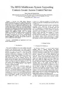
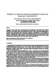
and indices required for all experiments. This ensures that no disk access was required in Oracle for the RDB approach. To ensure that same set of events are generated by simulator in both RDB and our approach (denoted as “R” approach), same seed was used for generation of random numbers in both the approaches. The parameters of our experimental analysis are chosen as shown in table 2. During the experiment we measure (i) the time it takes to identify primitive EIs, we denote this time as “Time to identify Primitive EI” (TP) (ii) the time it takes to identify composite EIs, we denote this time as “Time to identify Composite EI” (TC). The total time required to process an input basic event will be the sum of TP and TC. To compare the performance of our “R” approach with the “RDB” approach, we first initialize the EIDB with 2000 composite EIs and we programmatically simulate the basic event generation and send basic events to RFID EH at a fixed rate (50 basic events per seconds). We continue this for 5 minutes. We note the TP and TC for each basic event. We compute the average value of all TP and TC during the run for 5 minutes. We repeat this process for each value of number of composite EIs in the EIDB as given in Table 2. In all cases, we keep the rate of incoming basic events constant at the base value 50 per seconds. We complete this experiment both for “R” and “RDB” case. In Figure 5 and Figure 6, we plot the TP and TC respectively as it varies with the number of composite EIs in EIDB. As can be seen, at any number of composite EIs our approach provides much lower value of TP and TC compare to RDB approach. The more number of composite EIs will require more search time in the R-tree in “R” case and in the database in “RDB” case. Thus as number of composite EIs increases, the TP increases both for “R” and “RDB” case. The improved performance of “R” approach can be explained due to mainly two reasons (i) R Tree - The R-Tree approach of finding primitive EIs is taking 13 rd time of that being taken by the SQL query in Oracle inmemory database (ii) State Diagram - Representing composite EIs as state diagram means maximum one operation per basic event to determine whether the composite EI has occurred or not, whereas in “RDB” approach this requires computing the boolean 1 th of that function based on matching primitive EI. As a result TC in “R” approach is 20 of “RDB” approach. To demonstrate the scalability of our approach we kept the number of composite EIs in EIDB constant at its base value 10000. We varied the rate of incoming basic events in our system. For each value of rate of incoming basic events, we measured the total time (TP + TC) required to process each basic event and average it over 5 minutes. We plot the total processing time with the rate of incoming basic events in Figure 7. The y-axis
246
K. Dutta et al.
Time (micro-seconds)
20000
RDB R
15000
10000
5000
2000
3000
4000
5000 6000 7000 8000 Number of Composite EI
9000
10000
Fig. 5. Variation of TP with # EIs
250000 RDB R Time (micro-seconds)
200000
150000
100000
50000
0 2000
3000
4000
5000 6000 7000 8000 Number of Composite EI
9000 10000
Fig. 6. Variation of TC with # EIs
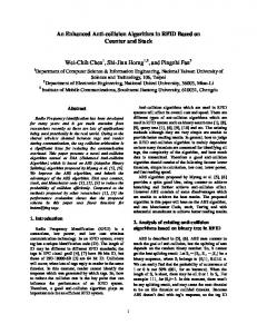
denoting “Average Processing Time” (i.e., TP + TC) starts at 18900. As the incoming rate of basic events increases the average processing time for each basic event increases gradually, however one should note that the increase in processing time is very minimal, from 19000 μseconds at 50 basic events per seconds to 19500 μseconds at 130 basic events per seconds. The complexity of composite EI should also affect the scalability of our system. One way to measure the complexity of a composite EI is the number of primitive EI it depends on as described in Section 3. We kept the total number of composite EIs in EIDB constant at the base value of 10000, the rate of incoming basic events to 50 per seconds and vary the average number of primitive EIs per composite EIs as described in Table 2. For each value of average number of primitive EIs per composite EI, we compute the average processing time of each basic event (TP + TC) over 5 minutes and report it in Figure 8. The y-axis denoting the ”Average Processing Time”
Average Processing time per Basic Event (micro-seconds)
Real-Time Event Handling in an RFID Middleware System
247
19500
19400
19300
19200
19100
19000
18900 60
80 100 Number of Basic Events per seconds
120
Fig. 7. Total Performance
Average Processing time per Basic Event (micro-seconds)
(i.e., TP + TC) starts at 18900 and the x-axis denoting the “Average Number of Primitive EIs per Composite EI” starts at 4. It is obvious that as the complexity of the composite EIs increases the system is taking more time to process each basic event and identify corresponding composite EIs, however the increase in processing time is very minimal compared to the increase in the complexity of composite EI - from 19000 μseconds at 4 primitive EI per composite EI to 19900 μseconds at 20 primitive EI per composite EI. Thus we can conclude that not only our approach of handling incoming RFID basic events provides much improved performance compared to “RDB” approach based on latest technologies, our approach also scales very well with increased rate of incoming basic events and the complexity of composite EIs giving real-time performance (few milliseconds) in all scenarios.
19800
19600
19400
19200
19000 4
8 12 16 Average Number of Primitive EIs per Composite EI
20
Fig. 8. Performance with Complexity of Composite EI
248
K. Dutta et al.
7 Handling Distributed RFID Events So far in the paper we have assumed a single instance of RFID EH where all RFID basic events are being gathered for identifying and handling EIs. If the number of event sources (i.e. RFID scanners) increases, both the number of basic events and EIs will increase. This may result in performance degradation of the centralized event handler system. Moreover in a centralized system, there is a potential risk of system failing even with single failure. The performance of the system, scalability and reliability can be improved by having a distributed event handling system. Moreover in real life situations raw RFID scans happen at distributed locations e.g. at various DCs or various stores in case of MG’s RFID deployment scenario. Each DC and store will have their own respective computer system to handle local data. Following this, in this section we briefly describe a distributed RFID event handler system that processes local basic events locally in local computer system and cooperate with other locations to address global business rules, that spans across multiple DC or multiple stores.
Fig. 9. Distributed Event Handler
Figure 9 depicts a schematic diagram of a distributed event handling system, where D1 , D2 ,...,D5 are local RFID event handler (EH) in local computer (e.g. local computer in DC). Local RFID basic events generated out of local RFID scanners are processed by the corresponding local RFID EH. However there are some events that require monitoring and combining basic events at two locations e.g. “the number of a pallets of a particular color in all DCs in Powai should not go below a certain threshold”. To identify such EIs it is necessary to consolidate basic events from multiple locations. For this in a simplistic brute force approach, basic events generated at location will be broadcast to all other locations. So each local computer system will be aware of basic events in other locations. However the obvious drawback for such brute force approach is increased overhead of communication cost. The communication cost can be reduced by designating primary handler for each global EI (a global EI is an EI corresponding to global business rules that require basic events from multiple locations) and keeping a distributed directory of global EI along with its primary handler. A number of variations
Real-Time Event Handling in an RFID Middleware System
249
Fig. 10. Location based Hierarchy in Distributed Event Handling
of such approach can be borrowed from distributed cache architecture and invalidation literature [23]. Typically, geographically distributed enterprise systems follow organizational hierarchy, e.g., in MG case, store specific systems communicate with the DC responsible for a region. Computer systems at regional DC communicate with state-wide DC and so on. In developing an efficient distributed RFID handler system we exploit such a hierarchy in the enterprise distributed system. Even if such hierarchy does not exist in other distributed systems of an enterprise, based on location we can create such hierarchy in the distributed RFID EH system of the enterprise. We group the EHs located at geographically distributed locations based on “location” parameter, which coincides with the location dimension (L) of an RFID basic event. An example hierarchy is shown in Figure 10. Here, we group city based store EHs (Miami and Fort Lauderdale) on the basis of the distribution centers (South Florida region) serving them. RFID basic events may arrive at any EHs in the hierarchy. The EIs are also specified at any EH in the hierarchy. An EI defined for a particular EH can have label dimension specified at the same level in the hierarchy or below it, e.g., at the label dimension (L) of any EI for EH at South Florida can have one of following values South Florida, Miami or Fort Lauderdale. When an EI is defined at an EH, corresponding primitive EIs are appropriately propagated to all respective EHs, e.g., when an EI oie = p1e ∧ p2e with label dimensions p1e .L=‘South Florida’ and p2e .L=‘Central Florida’ is specified at the EH in FL, the primitive EI p1e is passed to EH in South Florida and subsequently to EHs in Miami and Fort Lauderdale. Similarly the primitive EI p2e is passed to EH in Central Florida and subsequently to EHs in Tampa and Gainesville. At each level primitive events are stored along with the EH where the EI has been originally specified, in this case EH in FL for both p1e and p2e .
250
K. Dutta et al.
Assume a basic event be with L=‘Miami’ arrives at the EH in Miami. If EH identifies a match between be with p1e in all dimensions (L, S and T ) following the R-tree structure described in section 4, the be and p1e is passed to the EH in the immediate higher level, here the EH in South Florida. When EH in South Florida receives this message, it identifies that the p1e is for EH in FL and accordingly it passes this to the higher level until it reaches the appropriate EH in the hierarchy (in this case the EH in FL). Few noteworthy properties of this scheme are 1. Basic events are screened at the level where a basic event is first reported. Thus if a basic event does not meet any of the EIs in the system the basic event will not be processed and propagated to the higher level in the hierarchy. This distributes the identification of EIs across all EHs. 2. Conditions of an EI is evaluated where an EI is originally specified, e.g., in our example any condition related to composite EI oie will be checked in the EH at FL. 3. Once a primitive EI is identified to match a basic event, intermediate nodes passes the basic event and identified primitive EI to higher level. The identification of a primitive EI for a basic event happens only once at the EH where basic event first arrives in the system. 4. A single basic event may identify multiple primitive EIs and accordingly multiple message may need to be passed to higher level. 5. Number of basic events processed at each EH is limited by the number of basic events being first reported in the system at that EH, making it a very efficient scheme for EI identification.
8 Conclusions In this paper we described the architecture of a system that can handle large number of incoming RFID events and identify events of interest in real-time. We developed an event based model for RFID system using the ECA framework. We demonstrated that our approach in identifying RFID events of business interest can perform significantly better than an implementation using latest technologies. Lastly we described how our approach can be extended in a distributed scenario. In future we intend to implement the distributed architecture for RFID event handling mechanism and show the performance of our proposed distributed architecture.
References 1. 2. 3. 4. 5. 6. 7.
Glover, B., Bhatt, H.: Rfid essentials - theory in practice (2005) IDTechEx: Rfid progress at wal-mart (2005) TechWeb: Albertsons launches rfid initiative (2005) RFID Journal: Rfids in pharmaceuticals (2005) RFID Journal: Rfids in healthcare (2005) Ton, Z., Dessain, V., Stachowiak-Joulain, M.: Rfids at the metro group (2005) Gonzalez, H., Han, J., Li, X., Klabjan, D.: Warehousing and analyzing massive rfid data sets. In: ICDE 2006. Proceedings of the 22nd International Conference on Data Engineering, p. 85 (2006)
Real-Time Event Handling in an RFID Middleware System
251
8. Paton, N.W., D´ıaz, O.: Active database systems. ACM Comput. Surv. 31(1), 63–103 (1999) 9. Nagargadde, A., Varadarajan, S., Ramamritham, K.: Semantic characterization of real world events. In: Zhou, L.-z., Ooi, B.-C., Meng, X. (eds.) DASFAA 2005. LNCS, vol. 3453, pp. 675–687. Springer, Heidelberg (2005) 10. Hoag, J., Thompson, C.: Architecting rfid middleware. IEEE Internet Computing 10(5), 88– 92 (2006) 11. Sun Microsystems: Software solutions: Epc and rfid (2006) 12. IBM Inc.: Integrate your enterprise application with ibm websphere rfid middleware (2006) 13. Chakravarthy, S.: Sentinel: an object-oriented dbms with event-based rules. In: SIGMOD 1997. Proceedings of the 1997 ACM SIGMOD international conference on Management of data, pp. 572–575. ACM Press, New York, NY, USA (1997) 14. Chakravarthy, S., Le, R., Dasari, R.: Eca rule processing in distributed and heterogeneous environments. In: Proceedings of the International Symposium on Distributed Objects and Applications, pp. 330–339 (1999) 15. Hanson, E., Carnes, C., Huang, L., Konyala, M., Noronha, L., Parthasarathy, S., Park, J., Vernon, A.: Scalable trigger processing. In: Proceedings. of 15th International Conference on Data Engineering, pp. 266–275 (1999) 16. Rao, J., Doraiswamy, S., Thakkar, H., Colby, L.S.: A deferred cleansing method for rfid data analytics. In: Proceeding of VLDB Conference, pp. 175–186 (2006) 17. Jeffery, S.R., Garofalakis, M.N., Franklin, M.J.: Adaptive cleaning for rfid data streams. In: Proceeding of VLDB Conference, pp. 163–174 (2006) 18. Subramaniam, S., Palpanas, T., Papadopoulos, D., Kalogeraki, V., Gunopulos, D.: Online outlier detection in sensor data using non-parametric models. In: Proceeding of VLDB Conference, pp. 187–198 (2006) 19. Song, J., Kim, H.: The rfid middleware system supporting context-aware access control service. In: ICACT 2006. Proceedings of The 8th International Conference Advanced Communication Technology, 2006, p. 4 (2006) 20. Hoag, J., Thompson, C.: Architecting rfid middleware. IEEE Internet Computing 10(5), 88 – 92 (2006) 21. Guttman, A.: R-trees: a dynamic index structure for spatial searching. In: SIGMOD 1984. Proceedings of the 1984 ACM SIGMOD international conference on Management of data, pp. 47–57. ACM Press, New York, NY, USA (1984) 22. Oracle Inc.: Oracle database 10g express edition (2006) 23. Pong, F., Dubois, M.: Verification techniques for cache coherence protocols. ACM Comput. Surv. 29(1), 82–126 (1997)