REAL-TIME FACE RECOGNITION ON A MIXED SIMD VLIW ARCHITECTURE Hamed Fatemi, Hammed Ebrahimmalek, Richard Kleihorst, Henk Corporaal and Pieter Jonker Eindhoven University of Technology Den Dolech 2, NL-5600 MB Eindhoven, The Netherlands Phone: +31 (0)40 247 3394 Email:
[email protected] Abstract—-There is a rapidly growing demand for using intelligent cameras for various applications in surveillance and identification. Most of these applications have real-time demands and require huge processing capacity. Face recognition is one of those applications highly in demand. In this paper we show that we can run face recognition in real-time by implementing the algorithm on an architecture which combines a massively parallel processor with a high performance Digital Signal Processor. In this project we focus on the INCA+ intelligent camera. It contains a CMOS sensor, a Single Instruction Multiple Data (SIMD) processor [1] and a Very Long Instruction Word (VLIW) processor. The SIMD processor enables high-performance pixel processing and detects the interesting (face) regions from the video. It sends the regions of interest to the VLIW processor, which performs the actual face recognition using a neural network. With this architecture we perform face recognition from a 5-persons database at more than 200 faces per second. The performance is better than high-end professional systems that are in use now [2]. Keywords—-Face detection; face recognition; smart camera; intelligent camera; SIMD processor; VLIW processor; real-time image processing
1. INTRODUCTION Recently, face detection and recognition is becoming an important application for intelligent cameras. Face detection and recognition requires lots of processing performance if real-time constraints are taken into account[3]. It is difficult, because for a robust recognition, the face needs to be at a proper angle and completely in front of the camera. Also, the size of the face has to be spanning the correct range of pixels. If the face portion of the image does not contain enough pixels, a reliable detection cannot be made. What we want to show in this publication is that it is possible using thought-over smart camera architectures to achieve good, real-time face recognition results. A “smart camera” is hereby defined as a stand-alone programmable device with a size equal to or smaller than a typical video surveillance camera. In our situation it is programmed in
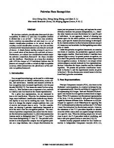
Figure 1: INCA camera such a way that video goes in and the names of recognized people come out. One of the main platforms for proper face recognition is using an Intelligent Camera (INCA+) see Figure 1[4]. With this platform we can easily map face recognition in to a smart camera (INCA+), which performs in real-time. This paper contains these parts: In Section 2 we explain about the architecture of camera, In 3 and 4 we explain about The algorithm that we used for face detection and recognition. The results are given in Section 5 and conclusions are drawn in Section 6. 2. ARCHITECTURE Face recognition consists of a face detection and face recognition part. In the detection part faces are detected in the scene and the relevant parts of the image are forwarded to the face recognition process where the found face is matched to a database with a set of stored faces in order to recognize and put an identification to it. These two parts of the algorithms work on different data structures. While the detection parts works on all pixels of the captured video and is pixel oriented (low level image processing), the recognition part is working on face
database
Sensor
color (RGB) video
Xetal Parallel Processor
CMOS Sensor Face Detection Part
recognized face(ROI)
Trimedia
ID
VLIW processor Face Recognition Part
Figure 2: Architecture of the INCA Camera
Figure 4: Xetal Architecture directly reads the pixels from the CMOS image sensor and performs the face detection part. Coordinates and subregions of the image where prospective faces are found are forwarded to the TriMedia. The TriMedia exploits limited instruction level parallelism; it can handle 5 operations in parallel. This processor scales the subregions and matches them to the faces in his database. In the fashion of a real “smart” camera, only IDs are reported to the user. 3. FACE DETECTION
Figure 3: RGB Bayern pattern objects and is face oriented(high level image processing). The recognition part works with a few hundred faces per second but has a high amount of operations in an iterative way while a database is “scanned”. The different aspects of the two algorithmic tasks have made us to choose for a dual processor approach where the low-level image processing approach of the face detection part is mapped to a massively parallel processor “Xetal” [1] and the high level image processing part of recognition to a high-performance fully programable DSP core “TriMedia” [5]. For the defined task the two processors can be simply connected in series as in Figure 2. The operating system also runs on Trimedia. First part of the architecture is CMOS sensor, it can send image to the SIMD processor.the sensor can take up to 30 frames per second with a resolution of 640 ∗ 480 pixels. The output of sensor is RGB bayern pattern where each pixel has one element. Moreover, if we want to have other elements we should interpolate with neighbor pixels see Figure 3. The Xetal processor exploits SIMD parallelism. It contains 320 pixel level processors and each pixel processor is responsible for 2 columns of image. It can handle up to 1000 instructions for each pixel as the same time. It has also 16 line memories to save information [1]. Figure 4 shows the Architecture of Xetal processor. This processor
In face detection we take an image from sensor and detect and localize an unknown number (if any) of faces. Before enabling the detection and localization, the image should be segmented to the region which face should be there. This is done by colour specific selection. By removing too small regions and enforcing a certain aspect ratio of the selected region of interest (ROI) the detection becomes more reliable. We detect faces in the image by searching for the presence of skin-tone coloured pixels or groups of pixels. The representation of pixels as they are delivered by the colour interpolation routines from the CMOS sensor image are in RGB form . This is not very suitable for characterizing skin colour. The components in RGB space not only represent colour but also luminance, which varies from situation to situation by going to a normalized colour domain this effect is minimized. The effect on the skin detection is that when a light condition changes the skin tone has also changed colour. With this feature the detection decreases in reliability. To solve this obstacle, there is the need to find for a colour domain which separated the luminance with the colour. The YUV colour domain is suitable for the detection because it separates the luminance (Y) with the true colours (UV). The YUV colour domain is also 3-dimensional and it has the shape of a cube. Y is the luminance and it is the brightness of a colour image as it would be displayed in a black and white monitor. The U and V are just components of the colour signal so that the colour image can be reconstructed. The Y value can vary from 0 to 255 whereas the U and the V
Output Nodes
Input Nodes 1
Hidden Nodes 1
2
1 2 2
o m Figure 5: Skin region in UV Spectrum
n
Figure 7: Architecture of RBF Neural Network works have a fast learning speed, and a very compact topology. 4.1. Architecture of RBF Neural Network
Figure 6: Skin Tone Result can have values from -128 to 128. By using the YUV colour domain not only the detection has become more reliable but the skin tone indication has become easier, because skin tone can now be indicated on a 2 dimensional space. The skin tone region is a square on the UV spectrum(Figure 5) and every not skin colour out of the ”skin box” is seen as non face(Figure 6). The face detection part only sends luminance and coordinate of face to recognition part. 4. FACE RECOGNITION The main goal of this section is to introduce the face recognition process. Through this process, the face detected in the previous section is identified with respect to the face database. For this purpose a Radial Basis Function (RBF) neural network is used [6]. The reason behind using an RBF neural network is its ability for clustering similar images before classifying them. RBF based clustering received wide attention in the neural networks community. Apart from good clustering capabilities RBF net-
An RBF neural network structure is demonstrated in Figure 7. Its architecture is similar to that of a traditional three-layer feed forward neural network. The input layer of this network is a set of n units, which accepts the elements of an n-dimensional input feature vector (here, the RBF neural network input is the face which is gained from the face detection part. Since it is normalized with a 64∗72 pixel face, it follows that n = 4608). The input units are completely connected to the hidden layer with m hidden nodes. Connections between the input and the hidden layers have fixed unit weights and, consequently it is not necessary to train them. The purpose of the hidden layer is to cluster the data and decrease its dimensionality. The RBF hidden nodes are also completely connected to the output layer. The number of outputs depends on the number of people to be recognized (for example, for 100 persons o = 100). The output layer provides the response to the activation pattern applied to the input layer. The change from the input space to the RBF unit space is nonlinear, whereas the change from the RBF hidden unit space to the output space is linear. The RBF neural network is a class of neural networks, where the activation function (basis function) of the hidden units is known by the distance between the input vector and a prototype vector. The activation function of the RBF hidden node is stated as follows [7]: Fi (x) = Gi (k x − ci k2 /σi ),
i = 1, 2, . . . , m (1)
where x is an n-dimensional input feature vector (normal-
// compute output of hidden node L1: for 0 < i < Number_Hidden_Node{ sum =0 for 0