MULTIBODY DYNAMICS 2011, ECCOMAS Thematic Conference J.C. Samin, P. Fisette (eds.) Brussels, Belgium, 4-7 July 2011
REAL-TIME HARDWARE-IN-THE-LOOP SIMULATION OF A HEXAGLIDE TYPE PARALLEL MANIPULATOR ON A REAL MACHINE CONTROLLER Javier Ros⋆ , Roberto Yoldi⋆ , Aitor Plaza⋆ and Xabier Iriarte⋆ ⋆ Mechanical
Engineering Department Public University of Navarre, Campus de Arrosadia s/n, 31006 Pamplona, Spain e-mails:
[email protected],
[email protected],
[email protected],
[email protected] web page: http://www.imac.unavarra.es/
Keywords: Hardware in the Loop, Real-Time, Multibody, Symbolic, Parallel Manipulator. Abstract. A virtual implementation of the Hexaglide type parallel robot at our lab is developed in the open source EMC2 (Enhanced Machine Controller v2) machine controller running on RTAI Real-Time Linux. This HiL simulation allows us to implement the different experiments and algorithms before deploying them safely on the real system. State of the art algorithms are proposed to efficiently perform the system state integration in Real-Time. The symbolic library LIB3D_MEC-GiNaC is used to export the required matrices in a very efficient way. Three different parametrization strategies are implemented and compared. Excellent Real-Time performances are obtained.
1 ISBN 978-2-8052-0116-5
Javier Ros, Roberto Yoldi, Aitor Plaza and Xabier Iriarte
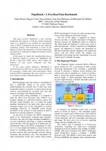
1 Introduction Numerical simulation of system dynamics is today a standard practice in robot design. The multibody system (MBS) analysis is commonly applied in the different design tasks related to robotics: kinematic and dynamic robot design, direct and inverse kinematic model setup, controller design, trajectory planning, and so on [3]. Simulations are frequently carried out as an off-line task. During the last years the MBS method has been established in the real-time simulation domain using Hardware-in-the-Loop (HiL) simulation for a large number of applications in mechanical engineering, including robotics [4]. HiL simulation provides an effective design and testing platform by adding the complexity of the plant under control to a real, or close to real, control hardware actuating the simulated or virtual plant. The Enhanced Machine Controller (EMC) [10] is an open (GPL) CNC software system for computer control of machines such as milling machines, lathes, plasma cutters, cutting machines, robots, hexapods, etc.. EMC has a user base, including hobbyist and professionals, distributed across all the world that is well over the thousands. It is a PC based control solution running Linux with the Real-Time Application Interface (Linux RTAI) [5, 6] and arbitrary motion control hardware. In this work we study the feasibility of Real-Time HiL simulations, using off-the-shelf PC running EMC as the control hardware, actuating over a Real-Time simulation of robotic systems. To that end, a realistic, complex and computationally demanding application example is presented in which the plant to be simulated corresponds to the research prototype of a Hexaglide type parallel manipulator of reference [11] depicted in Fig. 1. 2 Motivation The prototype of a Hexaglide type parallel manipulator shown in Fig. 1 has been designed and constructed as a test bed to get realistic design feedback of our research in the context of MBD [7]. Identification, calibration, new instrumentation and control experiments of different kinds are the main focus of our studies. In order to use a realistic and open testing environment EMC has been adopted as the machine controller environment. In our experience changes in the hardware, new unskilled users, controllers, identification strategies, experiments,... frequently produce undesired errors that can compromise the integrity of the machine and of people: unexpected movements, bangs,... are frequently produced. In order to reduce the likelihood of such a kind of problems to a minimum it was decided to develop a safe HiL environment in which the real controlling hardware (PC + EMC) is used to control a virtual Real-Time model of the Hexaglide (including kinematics and dynamics, drive, motors, and the encoder with index, and switch limits sensors) in which the experiments can be tried out first. This environment is not only appropriate to safely test the new configurations, instrumentation, and algorithms, but also to give a very valuable feedback about the non-idealities (jitter, quantization,...) of the control process related to the particular PC hardware and EMC tunning in an isolated way. The environment can also be used as an intermediate step in the design of a manipulator, as a user learning environment for EMC, and as a testing platform for the EMC’s developer community as well.
2 ISBN 978-2-8052-0116-5
Javier Ros, Roberto Yoldi, Aitor Plaza and Xabier Iriarte
3 Methodology EMC architecture is schematically represented in Fig. 2. It is a collection of components, programs and kernel modules, with clearly defined functionalities that work together to control the robotic system at hand. There are two types of components, user space components and Real-Time components. User space components are programs that are used for non critical tasks that do not need strict Real-Time requirements. This includes user interfaces (GUI, there are several available), the GCODE interpreter or task manager (EMCTASK), and a component for input output operations not strictly attached to the motion control (EMCIO). Real-Time components are implemented as kernel modules, that are administered by the Linux/RTAI Real-Time infrastructure. The main component of EMC in this category is the motion director (EMCMOT). The motion director basically receives coarse grained trajectory data in Cartesian (World) coordinates and interpolates them to generate a trajectory at the frequency needed by the controller thread, and to satisfy restrictions on maximum velocities and accelerations. This module, interfaces with the kinematics module, that helps the motion director to transform the commanded position in Cartesian coordinates to Commanded position in actuator (Joint) coordinates, and actuator feedback position into Cartesian coordinates. Commanded joint coordinates define the inputs of the specific controller that will be used. Obviously the particular kinematic module used should match the particular geometry and architecture of the actual robotic system being interfaced. Since version 2, EMC provides a HAL (Hardware Abstraction Layer) system. Thanks to the flexibility conferred by this layer, EMC is able to retrofit the vast majority of robotic systems. It also allows to modularly increase the functionality of EMC in a very easy and standardized way. The basic unit in HAL is the component, these can be user-space or kernel-space (Real-Time). Specific tools are provided, that can be used to make easy the programming of new components. Components stand for subsystems with a specific functionality. Components have pins, that can be connected to other components with wires that transmit signals between them. A Component can exhibit also parameters, that can be adjusted to alter the behavior of the component. A typical example of component is the PID component. This component has an output pin to drive the output of the PID, and two input pins, one for the commanded input and other for the feedback. PID parameters are related to the gains, limits,... From a programmatic point of view, modules (usually programmed in C) have an initialization and a finalization function, and an arbitrary set of functions, aimed to be called at regular intervals that implement the functionality of the module. That is, how the outputs are determined in terms of the inputs. When launching the HAL environment different threads can be settled up. In our application, a single thread, called servo thread that runs at a 1 ms interval is used. First components are loaded. When loading a component its initialization function is called, this mainly exhibits the pins, parameters and functions to HAL. Then HAL can be instructed to establish wirings between the pins of the components. To get something actually done, some of the functions provided by the loaded components have to be assigned to a given thread. In this way, upon start, the thread will be called sequentially at the defined period; at each invocation of the thread the functions assigned are called in the order in which they were placed on the given thread. HAL can also be used standalone. It also provides the "halui" component that allows it to be interfaced by arbitrary applications, including the different EMC interfaces. In a similar way HAL can provide modules to interface the hardware attached to the PC.
3 ISBN 978-2-8052-0116-5
Javier Ros, Roberto Yoldi, Aitor Plaza and Xabier Iriarte
This includes specific PCI boards and Parallel Port boards devoted to motion control, although any hardware attached to the PC can be interfaced. To that end it suffices to define a new HAL component that interfaces the corresponding Linux driver.
Figure 1: The controlled hexaglide manipulator.
Figure 2: Simplified Structure of EMC.
The approach to be followed to do the Real-Time HiL simulation of the Hexaglide is to substitute the HAL module interfacing our motion control hardware (Vital Systems MOTENC-100 PCI board) with an ad-hoc HAL module in which the simulation of the Hexaglide and sensors is performed (see Real-Time Hardware Devices Block in Fig. 2) to replace the, otherwise real, signals readings coming from the robot. The MOTENC-100 hardware driver kernel module actually used with the real hardware is used as a starting point. The driver has a very concise interface that allows to read the encoder position, the limit switches, and the index pulse of the encoders, and to write the value in Volts that is given to the motors drives and to read and write the index-enable flag (needed along the referred index-pulse to implement the homing strategy). First the read and write Real-Time functions of the driver, that are regularly executed in the PID thread, are rewriten to be the interface functions between EMC and the state of the virtual hardware to be simulated, and not the registers physically allocated in the PCI board. Second, a new Real-Time function is defined in which a one step integration of the forward dynamics of the virtual system is done. The period of the thread is used as the time step, and it is supposed that the values of the first 6 analog inputs are the inputs from the 6 PID. The value outputted by virtual sensors (encoders, index pulse and switch limits) is computed and written in the same function just after the integration in the first six encoder outputs. This function has to be added to the PID thread after the function that performs the Digital to Analog writing 4 ISBN 978-2-8052-0116-5
Javier Ros, Roberto Yoldi, Aitor Plaza and Xabier Iriarte
operation. The resulting HAL component is called “motenc_hexaglide_dyns_virtual”. As it has been previously commented, interfacing with a real system requires also a kinematics module, that implements the Inverse and Forward kinematic models of the robot. The interface of this module with the motion director module specifies the so called Joint coordinates, that are the coordinates of the actuated joints with respect to the HOME position, and the so called World coordinates, that are X, Y, Z Cartesian coordinates of the reference point of the head, and Euler angles in the order 3 → 2 → 1 that are called C, B, A. In the following the world coordinates will be called Cartesian coordinates and the joint coordinates actuator coordinates. The resulting HAL module is called “hexaglidekins”. The implementation of the models in the “hexaglidekins” module is entirely independent of the one that is needed in “motenc-hexaglide” to simulate the system. The only restriction is that the actuator coordinates must have the same meaning in both modules. The forward an inverse kinematic model formulations that are implemented into the “hexaglidekins” module are presented in Sec. 4.1. The dynamic and related kinematic formulation that is used to implement the one step forward dynamic integration on “motenc_hexaglide_dyns_virtual” is described in Sec. 4.2. 4 System Description The hexaglide family members are characterized by the use of six linear guides to control the six positions and orientations of the mobile head. To that end the head is attached to each of the carriages using a bar of constant length as shown in Fig. 3. In our implementation, the joint with the carriage is a spherical joint while the ones with the platform are universal joints.
B11
A31 A 22
A32 A11
Op
A21
A12 Ab11
O
Figure 4: Naming schema used
Figure 3: The hexaglide.
4.1 Kinematic models The vector of generalized coordinates q = [zT , cT ]T , is composed of the vertical coordinates of the carriages, z = [z11 , z12 , z21 , z22 , z31 , z32 ]T , and of the 3 Cartesian coordinates and 3 Euler angles of the head, c = [X, Y, Z, A, B, C]T . We do this to preserve symmetry, and because the position control of the CNC software is based exactly on these coordinates.
5 ISBN 978-2-8052-0116-5
Javier Ros, Roberto Yoldi, Aitor Plaza and Xabier Iriarte
The coordinate level constraint equations are defined by fixing to l the distance between the points Bij and Aij , i = 1, 2, 3, j = 1, 2 (see Fig. 5) of the carriages and head:
Φ(q) =
.. . Bij Aij · Bij Aij − l2 .. .
= 0;
i = 1, 2, 3;
j = 1, 2.
(1)
It is easy to obtain an explicit inverse kinematic model, zij = fij (X, Y, Z, A, B, C);
i = 1, 2, 3;
j = 1, 2,
(2)
because the ij-element in Eq. 1 is of the form φij = φij (zij , X, Y, Z, A, B, C), and is quadratic in zij . A forward kinematic model in explicit form is not known, so a Newton-Raphson procedure, k k ck+1 = ck − Φ−1 c (q )Φ(q ), k = 1, . . .
(3)
is used to solve the forward kinematic problem. Eqs. 2 and 3 are used to solve the inverse and forward kinematic problems. In EMC, the “hexaglidekins” Real-Time kernel module is developed for this particular application. For performance reasons, the algebraic operations (inverse, product,...) are implemented within the same module. Constraint equations at velocity level are not needed for the proper operation of the kinematic module of EMC. 4.2 Dynamic model In order to develop the dynamic equations, the rotation of the bars with respect to the carriages need to be described. To that end, six couples of angles, two for each bar, are introduced, a = [φ11 , θ11 , φ12 , θ12 , φ21 , θ21 , φ22 , θ22 , φ31 , θ31 , φ32 , θ32 ]T . These coordinates represent the spherical angles of the bars with respect to the carriages. The intrinsic rotation of the bar around its own symmetry axis is neglected. Note that inertia, as well as rotation, are negligible in that rotational direction. So, “a priori”, we will deal with iT h a different generalized coordinate set when dealing with the dynamic model q = zT , dT =
h
iT
zT , aT , cT . The coordinate level constraint equations are defined by matching the position of the extreme of the bar next to the head Abij and the corresponding attaching point of the head Aij , i = 1, 2, 3, j = 1, 2 (see Fig. 5):
Φ(q) =
.. . b Aij Aij .. .
= 0;
i = 1, 2, 3;
j = 1, 2.
(4)
The position problem that gives the dependent coordinates d in terms of the independent coordinates z, is solved using a Newton-Raphson procedure k k dk+1 = dk − Φ−1 d (q )Φ(q ), k = 1, . . .
(5)
The velocity problem that gives the dependent velocities d˙ in terms of the independent velocities ˙ is solved as follows: z, ˙ k = 1, . . . d˙ = −Φ−1 (6) d Φz z, 6 ISBN 978-2-8052-0116-5
Javier Ros, Roberto Yoldi, Aitor Plaza and Xabier Iriarte
¨ in terms of the independent The acceleration problem that gives the dependent accelerations d accelerations ¨z, is solved as follows: ¨ = −Φ−1 Φz ¨z − Φ−1 Φ ˙ q q, ˙ k = 1, . . . d d d
(7)
The dynamical equations are obtained based on the virtual power principle, also called Jourdain’s principle, for the set of generalized coordinates q, ¨ + ΦTq λ = Qq . Mqq q
(8)
As we want to have Real-Time performance we first reduce the size of the problem, and express it in terms of the independent coordinates. As, ¨= q
"
1 −Φ−1 d Φz
#
z¨ +
"
0 ˙ ˙ −Φ−1 d Φq q
#
h
.
(9)
T Then substituting Eq. 9 in Eq. 8 and multiplying the result by 1, (−Φ−1 d Φz )
"
1 −Φ−1 d Φz
#T
Mqq
"
1 −Φ−1 d Φz
#
z¨ +
"
#!
0 ˙ ˙ −Φ−1 d Φq q
=
"
iT
1 −Φ−1 d Φz
it is obtained
#T
Qq .
(10)
In this way the only unknowns are the independent accelerations z¨. Note that the Lagrange multipliers disappear from the equations. It is still possible to remove the operations with the 0 and 1 entries in the previous equations. To that end we consider the block partitions Mqq =
"
Mzz Mzd MTzd Mdd
Qq =
"
Qz Qd
#
#
,
.
(11)
(12)
Finally, this allows us to express the dynamic equations as (Mzz + Mzd A + (Mzd A)T + (AT Mdd )A)¨z = Qz + AT Qd − (Mzd + (AT Mdd ))b, (13) where and
A = −Φ−1 d Φz
(14)
˙ ˙ b = −Φ−1 d Φq q.
(15)
Parenthesization has been used in the previous expression to exhibit the order of computations with a minimal footprint. 5 One step integration As it has been said, the virtualization of the hexaglide requires to perform the integration of the state [qT , q˙ T ]T each time that a new output of the PIDs is written to the virtual driver. When the driver is loaded, the state is initialized with values compatible with the constraints equations at the position and velocity level. First z and z˙ are set to zero, then the values of d and d˙ are computed using Eqs. 5 and 6, respectively. 7 ISBN 978-2-8052-0116-5
Javier Ros, Roberto Yoldi, Aitor Plaza and Xabier Iriarte
After initialization, each time that the driver is written, a one step integration of the state is ¨ computed using Eq. 7. Then an improved performed. First z¨ is computed using Eq. 13, then d Euler scheme (1st order vel., 2nd order pos.), is used to evaluate the new state [qT , q˙ T ]T . Then constraints are “stabilized”, solving the position and velocity problem as described in Eqs. 5 and 6. For performance reasons, a single iteration is performed by the Newton-Raphson procedure, and the different matrices and vectors appearing are computed once per cycle. In particular, independent Jacobians, Φz and Φd , and the matrix A, are computed just before the single step Newton-Raphson procedure (those matrices are known after the initialization, when the first integration step starts). Note that the full state is integrated, and then only a O(∆t)3 error can affect to the evaluations of the Jacobian before the constraint stabilization. The remaining matrices are computed just before they are needed. 6 Symbolic Implementation The Multibody Symbolic C++ library LIB3D_MEC-GiNaC [8] is used to symbolically obtain the kinematic and dynamic equations of the system and to export the matrices needed for the implementation of the algorithms described in Secs. 4.1 and 4.2. Both the kinematic an dynamic equations are obtained in such a way that we can take advantage of their recursive nature. The different matrices are obtained from equations written in a recursive way, and parenthesization is maintained (no expansion is used) to a maximum. In this way the resulting equations and matrices keep the underlying recursive structure in the form of parenthesization. In this way the compiler optimizations can take care of this structure and offer a much more efficient code. Additionally, in the exported matrices, constant expressions are evaluated only once, with a specific initialization call, an actualization function is provided where only the time varying expressions are updated. Atomization [9], that can be considered a compiler optimization technique, can be used when exporting such a matrix to make sure that repeated floating point operations are reduced to a minimum. 7 Results The time per integration step has been computed with three different approaches. 1. Standard approach: this is the modeling and solution approach described in Sec. 4.2. 2. Reduced Joints approach: The inertia of the bars are “exactly” replaced by a mass at the center of the bar. This requires the transference of masses from the bar to the platform and carriages, to maintain the equivalence of the model kinetics. Then the coordinates for the orientations of the bars (a) can be removed from the formulation. That is, coordinate set d becomes c. A performance increase is expected from this reduction in size of the parametrization because this carries a reduction in the size of many of the matrices introduced in Sec. 4.2. Nevertheless, the algorithm is the same that the previous one. 3. Reduced Cartesian approach: this is the same than the previous one but the head coordinate set, c, is taken as the independent coordinate set, and the actuator coordinate set, z, is taken as dependent. This implies that the very efficient inverse kinematics model presented in Sec. 4.1 can be used. Also Φz becomes diagonal and constant, and then the computation of A gets more than an order of magnitude smaller. Apart from this the solution algorithm is kept as in the previous cases. A further increase of the performance is expected. 8 ISBN 978-2-8052-0116-5
Javier Ros, Roberto Yoldi, Aitor Plaza and Xabier Iriarte
The time employed by the evaluation of the Direct and Inverse Kinematic models described in Sec. 4.1 (used in the ”hexaglidekins“ HAL component) is not analyzed, though it is much smaller than the one needed for integration. The results of performance tests are presented in Tab. 1. It is clearly seen that reducing to the halv the number of coordinates, also reduces to a half the CPU cycle time. Moreover, when using the reduced set of coordinates, the use of the head coordinates as the independent set, halves again the execution time. Standard Reduced Joints Reduced Cartesian
time/iterations 1.446e-04 s 7.680e-05 s 4.060e-05 s
Table 1: Results of performance tests.
Further improvements are still possible by using atomization and other advanced symbolic capabilities. For example all the computations needed to do one integration step, even the inverse of the 6 × 6 mass matrix in Cartesian coordinates, can be obtained as a single function. This will give a faster evaluation of the different matrices and matrix products because the compiler will have more room for optimization. Atomization [9], that can be considered a compiler optimization technique, can be used when exporting such a function to make sure that repeated floating point operations are reduced to a minimum. Fig. 5 presents a caption of the EMC CNC machine controller in action while virtually machining its own logo. Cartesian coordinates of the head are shown along the graphical representation of the milling task. Those positions are obtained from feedback positions through the use of the ”Inverse Kinematic Model“ presented in Sec. 4.1. Fig .6 presents a caption of the oscilloscope showing the z11 and z12 commanded positions (axis.0.joint-pos-cmd and axis.2.joint-pos-cmd) and actual positions (axis.0.joint-pos-fb and axis.2.joint-pos-fb). Although the trajectory that gives the time sequence shown in Fig. 6 is not particularly demanding, it can be still observed a little difference between the real positions of the actuators, and the commanded ones (obtained from commanded Cartesian positions through the use of the Inverse Kinematic model). 8 Conclusions Two Kernel Space Real-Time HAL components have been developed to allow the interaction of the different EMC interfaces with a virtual Hexaglide parallel manipulator that resembles the real Hexaglide prototype at our lab. The first module, the kinematics module implements the Inverse Kinematic model and is used within EMC to transform commanded Cartesian (world) coordinates to actuator (joint) coordinates, and to transform the actual actuator position feedback to Cartesian coordinates. The second module, appears to the EMC integrator or retrofitter specialist, in the form of a software driver with the same interface that the MOTENC-100 motion control board. This module, performs the initialization and integration of the state of the system. Also, to be able to work with a rich enough set of the different EMC interface characteristics, virtual sensorization of the virtual prototype has been implemented, including switch limits and index-enable behavior. State of the art algorithms and techniques are used to get the best possible Real-Time experience. The simulation shows an excellent behavior on the hardware used, exhibiting computation 9 ISBN 978-2-8052-0116-5
Javier Ros, Roberto Yoldi, Aitor Plaza and Xabier Iriarte
Figure 6: EMC2 HAL Oscilloscope recording while machining a CNC program with the RT virtual Hexaglide.
Figure 5: EMC2 interface AXIS machining a CNC program with the RT virtual Hexaglide.
times as low as 40µs per integration step. That is 4 times bigger than what is considered a negligible time amount in this context: the maximum jitter accepted as appropriate for typical robotic applications (10µs). Apart for non-modeled dynamical artifacts and parameter accuracy, the user/integrator experience does not differ at all from the one with the real system. Therefore the HiL system developed can be effectively be used as comfortable, safe and realistic testing environment before a suitable working implementation of a new design or experiment is tested on the real hardware. The same procedure can effectively be applied to virtualize different robotic systems. This approach is not only appropriate in the context of EMC; it is easily extensible to other contexts. The algorithms and implementation that have been proposed, based on exporting capabilities of LIB3D_MEC-GiNaC developed to this end, can be easily extended to deal with almost any kind of robotic system, sensors and interface cards, achieving the required Real-Time performance. REFERENCES [1] W. Schiehlen. Multibody system dynamics: Roots and perspectives. Multibody System Dynamics, 1, 149–188, 1997. [2] C. L. Bottasso, L. Riviello. Conditions for the Solution of Maneuvering Multibody Dynamics Problems. Proceedings of the ECCOMAS Thematic Conference in Multibody Dynamics, Milan, Italy, June 25–28, 2007. [3] Sciavicco, L., Siciliano, B.: Modeling and Control of Robot Manipulators. Springer, Berlin, 2000. [4] Marco Morandini , Pierangelo Masarati , and Paolo Mantegazza. A Real-Time HardwareIn-the-Loop simulator for robotics applications. Multibody Dynamics 2005, ECCOMAS Thematic Conference. Madrid, Spain, 2005.
10 ISBN 978-2-8052-0116-5
Javier Ros, Roberto Yoldi, Aitor Plaza and Xabier Iriarte
[5] L. Dozio and P. Mantegazza. Real time distributed control systems using RTAI. In Sixth IEEE International Symposium on Object-Oriented Real-Time Distributed Computing (ISORC), Hakodate, Hokkaido, Japan, 2003. [6] Real-Time Application Interface (RTAI). http://www.rtai.org/. [7] J. Ros, A. Casas, J. Nájera & I. Zabalza.Quantitative Feedback Theory Control of a Hexaglide type Parallel Manipulator. 5th Asian Conference on Multibody Dynamics, Kyoto, Japan, 2010. [8] J. Ros, L. Arrondo , J. Gil , and X. Iriarte. LIB3D_MEC-GiNaC, a Library for Symbolic Multibody Dynamics. Multibody Dynamics 2007, ECCOMAS Thematic Conference. Milano, Italy. 2007. [9] J.C. Samin and P. Fisette. Symbolic Modeling of Multibody Systems. Kluwer Academic Publisher, Dordrecht 2003. [10] Enhanced Machine Controller (EMC). http://www.linuxcnc.org/. [11] Hexaglide project at Applied and Computational Mechanical Engineering research group at UPNa. http://www.imac.unavarra.es/∼cnc.
11 ISBN 978-2-8052-0116-5