Real Time Neural Network-based Face Tracker for VR Displays 1,2
1
1
1
1,2
1
Javier I. Girado , Tom Peterka , Robert L. Kooima , Jinghua Ge , Daniel J. Sandin , Andrew Johnson , 1 1,2 Jason Leigh , Thomas A. DeFanti 1
Electronic Visualization Laboratory University of Illinois at Chicago
2
California Institute for Telecommunications and Information Technology University of California at San Diego
ABSTRACT Tracking technology for Virtual Reality (VR) applications typically requires the user to wear head-mounted sensors with transmitters or wires. This paper describes a video-based, realtime, low-latency, high-precision 3D face tracker specifically designed for VR displays that requires no sensors, markers, transmitters, or wires to be worn. One center camera finds the 2D face position using Artificial Neural Networks (NN) and recognizes and tracks upright, tilted, frontal and non-frontal faces within visually cluttered environments. Two more left and right (L/R) cameras obtain the 3D head coordinates using a standard stereopsis technique. This paper presents a novel idea to train the NN to a new face in less than two minutes, and includes background training to avoid recognition of false positives. The system utilizes diffuse infrared (IR) illumination to avoid computing time-consuming image normalization, to reduce illumination variations caused by the physical surroundings, and to prevent visible illumination from interfering with the user’s field of view. CR categories: I.5.1 [Computer Methodologies]: Pattern Recognition⎯Models⎯Neural nets; I.4.8 [Image Processing and Computer Vision]: Scene Analysis—Tracking; I.3.7 [Computer Graphics]: 3D Graphics and Realism−virtual reality; Keywords: head, face or camera-based tracking; Kohonen neural networks; autostereoscopic 3D display; virtual reality. 1 INTRODUCTION Creating credible VR worlds requires constant updating of images to maintain the correct perspective for the user. To achieve this, the VR system must incorporate a head tracker to know the exact position and orientation of the user's head. VR autostereoscopic are displays aimed at eliminating user encumbrances since require no stereo glasses to be worn. Therefore, it makes sense to require a tracking device that likewise requires no additional gear on the user’s part. Since this display paradigm has more stringent performance and latency display constraints than other passive or active stereo techniques [2], tracking performance requirements are also more demanding. The research described here is a cost-effective, real-time (640x480 at 120 fps) face recognizer and tracker that serves as video-based, tether-less 3D head position tracking system targeted for the Varrier [1] autostereoscopic display, but it is applicable to any tracked VR system. The user does not need to wear any sensors or markers, a departure from the original research [3][4] when the tracker was first presented at IEEE VR’04. The 2D head position technique is implemented using a Kohonen Artificial Neural Networks (NN) [17][18], whose rapid execution allows the system to recognize and track upright, tilted, frontal and non-frontal faces at high frame rates and low latency. This is an important factor in replacing commercially available tethered head trackers. Other advantage of an NN implementation is robustness and relative insensitivity to object partial occlusions and slight variations in the object view [12][13][14][15][16]. In developing video-based face recognition and tracking using E-mail:
[email protected]; URL: www.evl.uic.edu
machine learning, several problems arise: First, the NN has to be trained in advance with views of the face in order to later recognize and track it [5]. Training an NN for faces is usually a lengthy process that can take from hours to days and sometimes requires human intervention [5]. This is not acceptable for our purposes. Second, faces vary considerably with lighting and this can adversely affect the recognition and tracking [5]. Common solutions are to apply CPU-intensive pre-processing algorithms. Third, the tracker system has to deal with all the variations in distinguishing face objects from non-face objects to avoid falsepositives [5], necessitating training for possible non-face objects, another lengthy process. Finally, the tracker system has to recognize a target face from other possible faces so it can identify the correct users. Recognition is independent from tracking. This paper presents solutions to all of these problems. For example, it discusses several NNs, one for recognition at 10 frames per second (fps) and one for tracking at up to 320 fps. A fast (under two minutes) NN face and background training method is developed using an image-based technique. IR diffuse illumination reduces image dependency cause by room and display lighting variation, thereby avoiding image normalization and preventing shining visible light into the user’s field of view. A prediction module achieves faster frame rates once a face is been recognized. A database of already trained faces obviates the need to re-train the same user and affords recognition of a trained user’s face within a scene of several faces. Moreover, having a rich database of faces permits a new user to be tracked using a similar existing face, without the need for training at all. This is advantageous at conferences and other public venues when a large number of participants wish to take turns using the system. 2 BACKGROUND Examples of current techniques for addressing head tracking for projector and autostereoscopic VR displays include: DC/AC Magnetic pulse (e.g. Flock of Bird ® by Ascension Technology and FASTRAK® by POLHEMUS); Acousto-inertial (e.g. IS-900 by InterSense); Camera with markers (e.g. Vicon MX by Vicon, ARTrack1/2 by Advance Realtime Tracking GmbH and TRACKIR™ by NaturalPoint). All of these trackers require the user to wear head-mounted sensors with wires or wireless transmitters, or markers. Some have noteworthy specifications in terms of frame rate, accuracy, resolution, jitter, and large tracking coverage, but they are tethered or require gear to be worn. The only commercially available camera-based face tracker that does not use any markers at all is faceLAB™ from seeingmachines, which relies on a feature-based technique [6]. However, it has limited tracking volume and a maximum frame rate of 60Hz. In order to be appropriate for VR systems and to be competitive with commercial technologies, the new tracking system must meet the following requirements: accuracy in head localization, ample resolution to supply smooth 2D position transition, robustness to illumination and scene variations, and fast frame rate to provide low latency and smooth 2D tracking position. Our approach relies on video images grabbed by the cameras to find and track a particular face from the scene. Many different techniques or combinations of techniques have been proposed for tracking a user’s head based on sequences of images. Approaches to 2D face tracking are based on, for example, color [7][8],
templates [9], texture-map [10], Principal Component Analysis [11], and NN [5] techniques. NNs are a popular and proven technique for face recognition, detection and tracking. Comprehensive surveys can be found at [12][13][14][15][16]. There are several types of NNs to choose from [17], and each one is best suited for a specific application. The method of choice here is a NN called a Kohonen Net [17][18], which is further optimized to reach high tracking frame rates. An NN is not free from some drawbacks though. It needs to be trained with examples of the face in order to learn how to recognize and/or detect it [5][17]. The more samples of the same face (for recognition) the better the training. In order to attain accurate recognition (or detection) performance, training examples have to be carefully selected and prepared, usually requiring human intervention [5]. Published documentation on the amount of training time required is scarce, as training is usually considered an off-line process in NN literature. It can take from hours to days, especially when image samples need to be manually extracted from the background, aligned, etc. Image-based head tracking approaches are sensitive to variations caused by lighting or camera differences. One way to resolve this problem is to preprocess the images [5]. Standard algorithms such as histogram equalization to improve the overall brightness/contrast in the images, and lighting compensation algorithms that use knowledge of the structure of faces to perform lighting correction, are generally called image normalization [5]. Preprocessing uses CPU cycles that could be used to improve frame rate, if preprocessing could be avoided altogether. Some image-based techniques for face detection/recognition use a Convolutional Neural Network architecture [22] that does not requires any costly preprocessing, but the complexity of the NN prevents higher detection frame rates (e.g., 4 fps using Intel 1.6Ghz). There is always a trade-off between face recognition/detection performance and frame rate. The more complex the algorithms, the slower the system tends to run. Most related papers don’t post the frame rate and/or image resolution of their recognizer/detector. Target applications like VR need the highest possible tracking frame rate and low latency [20]; if the image presented is noticeably out of sync with the user's position, the user cannot function. 3 KOHONEN ARTIFICIAL NEURAL NETWORK
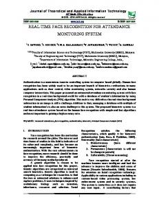
mode training. These are algorithms that adjust the weights in a neural network by only including the input training data set, without any kind of supervision. In the face tracker, the NN is presented with several images of a face in different poses during training, which it automatically incorporates in an unsupervised mode into clusters representing different poses of the user’s face. Each competitive unit or neuron corresponds to a cluster, the center represented by a weight vector w. All weight vectors (one for each neuron) form a weight matrix W. Fig. 1 shows a representation of a VQ Kohonen net and the relations between input vector x, output vector o, and weight matrix W. Each output oj of a Kohonen net is a weighted sum of its inputs xi, i , or in other words, the dot product between the input vector x and a weight vector wj: m
T
o j = ! wij xi = w Tj x, where: w j = "# w1 j ...wmj $% ,x = "# x1 ...xn $% (1) T
i=0
Therefore, the Kohonen output vector o is equal to the product between the weight matrix WT by the input vector x. The Kohonen NN classifies all similar input vectors into a class, producing a unity output in the same Kohonen neuron. After the training phase computes all the weights wij, an unknown case is presented to the NN. All outputs oj are found using Eq. 1 and the maximum output neuron is declared the winner, determining the class of this unknown case by a WinnerTake-All (WTA) strategy [29]. In other words, for any given input vector one and only Kohonen neuron output can be 1, and the rest of the neurons are 0:
owinner > o j! winner " owinner =
m
#w i=0
i winner
xi = 1, o j! winner = 0
Kohonen's learning algorithm finds the weights vector closest to each training case and then moves the winning weight vector closer to this specific training case. The weight vector moves proportional of the distance between it and the training case. This proportion is called learning rate factor, that is: w iwinner (t + 1) = w iwinner (t) + ! " (x i (t) # w iwinner (t)) where: w iwinner (t + 1) - the new value of winning weight vector w winner
!
- learning rate factor
x i (t) w
i winner
- current input i 'th sub-vector (t)
- current wining weight vector
Since after training each weight vector wj represents the centroid of a cluster or class, a confidence number ‘C’ is defined as the distance between the input vector and the weight vector of the winning neuron: C = |wwinner – x|. This confidence number reports how well the weight vector represents the input vector, that is, how close the input vector is to the class center. C = 0 implies a perfect match between the input vector and cluster center or weight vector. This confidence number serves to discard all input vectors whose distances are above a certain threshold, and this parameter enables recognition of similar faces to those stored in the database. 4 BASIC TRACKER SYSTEM Figure 1: VQ Kohonen net representation between input vector x, output vector o and weight matrix W.
The core of the face tracker is an arrangement of Vector Quantization (VQ) Kohonen Artificial Neural Networks, or VQ Kohonen nets [17][18][21]. Kohonen nets can quickly integrate new input data into existing clusters of data by analyzing and then classifying the data using connection weights that are modified through different training data iterations. This is termed a selforganizing neural network, one of many cases of unsupervised
The tracker system consists of two computers and 3 cameras (Figs. 2, 3) running at 120 frames per second (fps) and 640 by 480 monochrome pixel resolution. The center camera is connected to the Face Tracking Computer and performs 2D face recognition and tracking using several Kohonen nets. The remaining L/R cameras connect to the Stereopsis Computer that utilizes a standard block-matching correspondence technique to determine the 3D position of the tracked face.
Figure 2: Tracker system architecture.
Figure 3: Varrier display with 3D head tracker on top (left). Details of head tracker’s three cameras, IR illuminators and filters (right).
Several IR illuminators (see Fig. 3) surround the display to shed a uniform light over the tracked subject, and all cameras have visible light cut-off filters. A diffuse light area is constructed using these IR panels to minimize shadows and specular reflections that may interfere with the ability of the NN to recognize or track a face. The visible-cut filters prevent room and display illumination from entering the cameras, and IR light prevents blinding the user by directing visible light at the face. Training the NN takes place in the same controlled environment, and while running, the NN can cope with small variations in illuminations without affecting recognition or performance. The 2D face–tracker module consists of two Kohonen nets: the recognizer contains 128 neurons for recognizing a face and the tracker has 32 neurons for tracking the already recognized face. Initially, the tracker system loads a pre-learned face profile from the face database. Then it scans the entire video image attempting to recognize this face. If the system finds the user’s face, it then switches to tracking mode that runs at a higher frame rate than during recognition. During tracking, the tracker computer continuously sends the extracted face-image, its 2D center position, and the face width and height values to the stereopsis computer. These data are transported via a UDP/IP dedicated Gigabit Ethernet connection.
Figure 4: Triangulation.
The two outer stereopsis cameras’ coordinate axes are aligned, and their baseline T (line segment joining the optical centers OL and OR) is parallel to the camera x axis (Fig. 4). For the special case of non-verged geometry, a point in space projects to two locations on the same scan line in the L/R camera images. The resulting displacement of a projected point in one image with respect to the other is called disparity.
The correspondence problem [19] determines the 2D locations in each camera image that correspond to the same physical point in 3D space. Then, the computation of a 3D position of a point in space from the disparity and known camera geometry is performed using triangulation (Fig. 4). The depth of a point in space P imaged by two cameras with optical centers OL and OR is defined by intersecting the rays from the optical centers through their respective images of P, p and p’. Given the baseline distance between OL and OR and the focal length of the cameras, the depth z at a given point may be computed by similar triangles as z = baseline • focal_length / disparity, where disparity of P is x - x’ (Fig. 4). In order to relate this image information in pixels to the world coordinate system, the geometry of the cameras has to be computed with accuracy with a camera calibration process [19]. The stereopsis computer is grabbing video images simultaneously from the L/R cameras. Since the 3 cameras are aligned horizontally and the user’s face appears in the field of view of the 3 cameras, the face-template from the center camera is used to search for the same face in the L/R video images. Using the epipolar constraint [19], the search is restricted to same row position of the L/R camera images. The search of the face in both images is accomplished using a local correspondence method called Block-Matching [27], selected for its efficiency. Local correspondence methods are more sensitive to locally ambiguous regions in images (e.g. occlusion regions or regions with uniform texture), but faces seldom present uniform texture and partial occlusion rarely happens when a tracked user is looking straight at the cameras. Block matching methods seek to estimate difference at a point in one image by comparing a small region centered about that point (the template) with a series of small regions extracted from the other image (the search region). The epipolar constraint reduces the search to one dimension. Once the face is found in both images, the disparity is computed and thus the z depth of the tracked face is known. The final task of the stereopsis computer is to send the 3D head position to the VR system. 4.1 OPTIMIZATIONS A number of optimizations are appended to the basic system described above in order to increase performance and quality. Elimination of Preprocessing: Face recognition and tracking is a difficult problem because deviation in the face images due to illumination variations increases the complexity of the decision boundary between one face and another, and faces and non-faces. To reduce this variability, the input image is usually preprocessed either locally by equalizing and normalizing intensity across small regions, or globally for the entire image. Regardless, preprocessing is never perfect [5], and both methods use valuable CPU resources that are needed to achieve higher frame rate during tracking. Our solution is no preprocessing at all: the face tracking system works in the IR lighting domain and is nearly independent of variations in room illumination. Sum of Absolute Difference (SAD): Kohonen nets compute a dot product to determine the distance or similarity between two vectors. This involves vector multiplication and normalization, both costly operations. Fortunately, since tracking and training are performed in the same controlled illumination environment, normalization is no longer necessary. The dot product can be replaced with another metric that measures the distance between two vectors but does not involve any complex operations: the Intel Pentium IV multimedia assembler instruction called Sum of Absolute Difference (SAD). This instruction requires two CPU cycles to compute the absolute value of the difference of 16 unsigned bytes. These differences are then summed to produce an
unsigned 16-bit integer result. The algorithm is implemented using Intrinsics [28] to maximize its efficiency. Prediction: Once a face is recognized the system does not search into the entire video image again, only in a predicted 2D position. Our approach is very simple: the next probable 2D face position equals to last position plus the difference of last two positions. The size of the search area is twice the size of the face. Un-rectified center camera: To obtain 3D position information from a stereo pair of cameras exploiting the epipolar constraint, both L/R video-images have to be horizontally aligned, calibrated and rectified [19]. These processes take CPU time. Fortunately this is not necessary for the center camera since it only has to find and send the face-image with an approximate row position. In case the center camera has a small vertical offset with respect to the L/R cameras the stereopsis module searches L/R in an area of the camera images for a matching face-image. This area centers at the epipolar line and cover 10 pixels up and 10 pixels down. Synchronization: The L/R cameras have to be synchronized in order to reliably calculate the 3D face position. The center camera does not, for the same reasons as above, and at 120 fps the time difference of 8ms in acquiring the images is negligible. The L/R cameras are in the same FireWire bus and use auto-sync mode. Field of View Constraint: For the tracker and stereopsis algorithm to function, the 3 cameras have to see the subject at the same time; in other words, the user has to be in the combined field of view of the 3 cameras. (Fig. 2). This implies that the stereopsis module does not have to search for the face in the entire scan row of each L/R video image pair. Smoothing: To avoid possible jittering due to image noise and the inability of the neural network to find the ‘exact’ head center, a simple smoothing technique is applied. The average of the median of the last four 3D positions is reported. Five frames is a value based on experience that produces a reasonable degree of smoothing while minimizing added latency. 5 TRAINING To recognize any object, all NNs must know a priori the object to be recognized. Hence, a learning algorithm must teach the NN, a process called training [5][17]. To be effective and require an acceptable amount of training time, an NN must be able to extrapolate from a modest number of training samples. Thus, the face tracker NN must be presented with sufficient views of the face to extrapolate all possible poses of the face from these views. The challenge is for an unsupervised NN is to learn what a face is without prior knowledge, and to do so in a reasonably short time. 5.1 METHODOLOGY
Figure 5: Head tracker and Training user interfaces.
The user begins by sitting in front of the center camera. Video is then recorded while the user slowly executes a series of head poses (turning L/R, nodding up-down, tilting L/R, and leaning inout) over the course of 512 frames, or 26 seconds. This process allows the system to accommodate for the natural changes in the
user’s face orientations and position while interacting with the VR system. Once the recording is finished, the user manually superimposes two ellipses (Fig. 5) onto the first-frame image: the head-tracking ellipse and the neural-network ellipse. The ellipses are manually positioned to the center of the face and adjusted such that the size of the larger head-tracking ellipse is approximately the size of the head and the smaller neural-network ellipse is the size of the face. The width and height of the neural-network ellipse’s bounding box defines the width and height of the face, and face-size = facewidth * face-height determines the number of components in the input vector x for this specific user. This input vector will be masked with a face-width by face-height ellipse to extract the background from the face-image foreground. The resulting masked vector is the input to the neural network (Fig. 2). After this initial procedure, the NN is trained automatically for this user, requiring about two minutes depending on the user’s face-size. Once finished training, the system saves not only the recorded video but also the NN weight vectors under the user’s name, creating a record in the database of tracker users. After this process, the system automatically starts tracking the user. 5.2 ALGORITHM DESCRIPTION An image-based algorithm performs the automatic training. As mentioned above, two ellipses were manually centered around the face-image. The head-tracking ellipse sets the initial position for an ellipse-based head-tracker and the neural-network ellipse follows the face using a block matching motion estimation algorithm [30]. During the automatic NN training, both ellipses follow the face through the 512 frames of training data. Given that an ellipse-based method is used for training the NN, a reasonable question is why an ellipse-based tracker is not used for head tracking altogether, instead of an NN. These trackers tend to jitter around the center and may track other ellipse-shaped objects from the scene. Given the nature of these algorithms, their instability is understandable because they use a grid of pixels to determine either the gradient or the Hough transform, and this decreases their center resolution. We choose a head detector for training based on ellipse Hough transforms (HT) [23][24], which is slower than gradient methods [25][26] but more stable around its center. The algorithm works in this way: during the playback of the training video the block matching motion estimation algorithm moves the neural-network ellipse smoothly following the face. However, over time the neural-network ellipse can accumulate errors from the face center because IR light sometimes washes out face-image details. When presented with smooth textures this algorithm tends to fail in tracking the movement properly. However, since the head-tracking ellipse always follows the head, it can determine if the neural-network ellipse is drifting out of range and ‘nudge’ it back. Combining both methods guarantees that the neural-network ellipse smoothly follows the face. Then, frame-by-frame, pixels inside the neural-network ellipse are extracted and saved into a NN_Training array for later use. At the same time background pixels are saved into a Background_Training array. This is the scene without a user’s face since it was already extracted. The NN_training array now has 512 rows containing extracted face-images in different poses. Each row of this array is actually an image of the size face-size, but expressed as a vector. The Background_training array now has 512 rows containing extracted background with no user’s face. With the NN_training array, the training algorithm of Section 3 uses equation (2) to train the recognizer NN and the tracker NN. All elements of the Background_training array are averaged and saved it into a User_Background_average image.
5.3 BACKGROUND DETECTION It is easy to get a representative sample of images that contain faces, but more difficult to acquire representative samples of nonface images, because the non-face feature space is much larger than the face feature space [5]. To minimize the problem of mistakenly recognizing or tracking an area of the background as a face, the tracker system can automatically train for non-faces using the current background. We define the ‘current background’ as the view when: (a) no people are in field of view of the center camera and (b) the user’s face is extracted from the background. To acquire (a), the tracker system averages 512 video frames when no one is present in the camera field of view and saves it into a Background_average image. The data in (b) has already been obtained in the User_Background_average image from the NN training. The system uses a confidence ‘C’ number to determine the presence of a face. This C number is the measured distance using a SAD metric between the probable face-image from the video input and one of the faces stored as weights inside the NN. If the C number is above a certain threshold, the system considers the face-image as a face. To perform the background detection the face-image is compared against a sub-image extracted from the User_Background_average and from the Background_average at the same 2D face-center position using the same SAD metric to measure the distance between the two sub-images. If the confidence number is greater for either of the average background images than for the candidate face-image, then the candidate faceimage is actually a part of the background. Therefore the system ignores this area of the video image and continues scanning for the user’s face. This works well in our approach since the background is largely constant once the system is in use, and the IR illumination of the background is robust to changes in room lighting. 6 HARDWARE AND SOFTWARE SPECIFICATIONS The complete system runs on two machines with Dual Intel® Xeon CPU @ 3.60GHz. The code is implemented using the Intel® Integrated Performance Primitive (IPP) library and Intel Streaming SIMD Extension 3 (SSE3) Intrinsics [28]. Camera calibration is accomplished with the Small Vision System (SVS) Developer kit from SRI International. Cameras are IEEE 1394b PointGrey DragonFly Express. Visible light cut-off filters are B&W, near IR @ 650nm. Camera lenses are 4.6mm focal length, and the stereopsis camera baseline is 277 mm. 7 USE AND PERFORMANCE Once the system has been trained, the user can immediately be tracked. If the tracker system does not recognize or track the user around the center of the face, it can be re-trained by retrieving the recorded video from the database, re-centering both ellipses and re-training. Assume now that the tracker system has been trained with several faces stored in the database, if the user has been trained, the system will recognize the person and start tracking. But in many cases NN training is not necessary for a new user. Once the tracker system has enough faces in the database, the user can relax a neural network parameter called confidence threshold and ask the system to perform an automatic database search until it recognizes and tracks with a similar stored face. If the confidence is set too high, the new face must resemble the stored face closely. Alternately, if the confidence is set too low, other non-face objects are tracked. The recognition and tracking confidence levels are adjustable through a user interface (Fig. 5). During tracking this number also serves the important purpose of resetting the system to recognition mode if the
confidence is below the threshold. This happens when, for example, the tracked face disappears from the camera field of view. When the system is started, reset, or loses tracking it defaults to recognition mode: The system will scan the videoimage and try to find the face that closely resembles its stored profile. Once the user’s face is found the tracker system immediately resumes tracking mode. The tracker user has the option to manually load his or her profile. The measures in Table 1 were taken using 3D position reporting software with a display resolution of less than ± 3mm. Static jitter and drift were measured using observations of reported 3D position for several minutes, sampling every second, and averaging the minimum and maximum per X, Y, and Z coordinates. End-to-end latency was measured using the method of [20]. This quantity is the total system latency including 16ms rendering time, and is a measurement from when the tracked object moves until the display responds. Accuracy was measured with nine position samples within a 0.37 m2 area, and compared physical locations against reported 3D positions. Table 1: Comparison of camera-based and commercial tracker
Recognition frame rate (fps): Tracking frame rate (fps): Static Jitter ±(X,Y and Z in mm): Drift ±(X, Y and Z in mm): Latency (ms): Training time (min): Accuracy (X and Z in mm):
Camera-based tracker ~8 120/~320(max) < 3, < 3, < 3 < 3, < 3, < 3 80 ± 8