ICROS-SICE International Joint Conference 2009 August 18-21, 2009, Fukuoka International Congress Center, Japan
Real-Time Object Detection and Tracking on a Moving Camera Platform Cheng-Ming Huang1, Yi-Ru Chen1 and Li-Chen Fu1,2 1
Department of Electrical Engineering, National Taiwan University, Taipei, Taiwan ROC. Department of Electrical Engineering and Computer Science and Information Engineering, National Taiwan University, Taipei, Taiwan ROC. (E-mail:
[email protected])
2
Abstract: This paper presents a real-time tracking system to detect and track multiple moving objects on a controlled pan-tilt camera platform. In order to describe the relationship between the targets and camera in this tracking system, the input/output hidden Markov model (HMM) is applied here in the well-defined spherical camera coordinate. Since the detection and tracking for different targets are performed at the same time on a moving camera platform, the detection and tracking processes must be fast and effective. A hybrid detection algorithm which combines the target’s color and optical flow information is proposed here. A two layer tracking architecture is then utilized for tracking the detected target. The bottom level utilizes the Kanade-Lucas-Tomasi (KLT) feature point tracker which identifies the local point correspondence across image frames. The particle filter at top level, which maintains the relation between target and feature points, estimates the tracked target state. The overall performance has been validated in the experiments. Keywords: Visual tracking, Moving camera, Optical flow.
1. INTRODUCTION Visual surveillance in dynamic environment has drawn much attention nowadays. It has a wide spectrum of researches, including access control, human or vehicle detection and identification, multi-target visual tracking, detection of anomalous behaviors, crowd statistics or congestion analysis, etc. In order to construct a wide-area surveillance system economically, we utilize the limited field of view of one single camera to track multiple targets with might and main. This is the key concept and contribution in this paper. Detection and tracking of multiple targets at the same time is an important issue in a wide variety of fields recently. Our goal is to develop a hybrid multi-target detection and tracking system with real-time performance. In a general surveillance system with a single pan-tilt camera, the camera is typically installed at a fixed location. The camera can expand its field of view by commanding its pan and tilt motors. The target is tracked in the image plane, i.e., the target motion is observed with respect to the moving camera platform coordinate. In order to control the pan-tilt camera to dynamically track the moving objects, we construct a well defined spherical coordinate frame centered at the camera platform. The original image coordinate is then transformed into the spherical camera platform coordinate. Furthermore, the images, target states, and camera actions in this paper are all defined on the spherical camera platform coordinate system. Since we desire to track targets and keep on detecting new ones on a moving camera platform at the same time, the traditional motion detector based on the background subtraction can not be applied here. Other detecting techniques utilize the predefined target’s image information, such as a specified color histogram, a template model of texture, can still work in the moving camera scenario. However, they are sensitive to the lighting variation. Some other learning based detectors like the AdaBoost face detector [8] may not be
- 717 -
influenced by the lighting. When considering the detection and tracking objects at the same time, the learning based detectors are not fast enough such that the real-time performance can not be fulfilled. For the target tracking or high-dimensional estimate, the comprehensively search in the state space is computational expensive, thus making the system incapable of being real-time. The Monte Carlo method is one solution to this obstacle. By approximating the probability density function in state space with discrete samples, we can obtain the estimate from the sample set. Particle filter or sequential Monte Carlo (SMC), which is based on the Bayesian filtering framework, has been presented to estimate non-Gaussian and non-linear dynamic processes [17]. The sampling importance sampling (SIS) particle filter is also applied to visual tracking and cooperates with auxiliary information knowledge, which is well-known as ICONDENSATION algorithm [4]. Markov chain Monte Carlo (MCMC) [2] has been proven to perform excellently for drawing the particles. Single [3, 4] or multiple [2, 18] particle filters have their nature to efficiently represent multi-model distributions. There are a lot of researches about the target tracking on a moving camera and the camera action decision [6, 7]. The optical flow of local point in image sequence can be robustly evaluated by the Kanade-Lucas-Tomasi (KLT) feature tracker [1, 12]. Some researchers also employs the KLT tracker to improve the tracking performance [10]. However, the feature point tracker can only provide the point correspondence across frames which does not involve the concept of a target region or target state estimation. The rest of this paper is organized as follows. Section 2 first introduces the input/output hidden Markov model (HMM) and the spherical camera platform coordinate for tracking target on a pan-tilt camera. The particle filter for tracking target at top level together with the KLT feature tracker at bottom level is described in section 3. Section 4
PR0002/09/0000-0717 ¥400 © 2009 SICE
and state transition without control input by using the hidden Markov model (HMM). Since the targets states 0� t are estimated from the camera’s viewpoint and the designed camera control input ut will also influence the targets states in the spherical camera platform coordinate, we apply the input/output HMM [16] to represent the overall surveillance system. Figure 2 shows the graphical model of the input/output HMM, which can be utilized to visualize the dependencies between the targets and active camera in the spherical camera platform coordinate.
demonstrates the experimental results and efficiency of our system. The conclusion and future work are given in section 5.
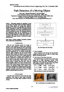
2. PROBLEM FORMULATION AND BAYESIAN INFERENCE In general surveillance system, the pan-tilt camera is set up at a fixed location. The camera can expand its field of view by commanding the pan and tilt motors. The target is tracked in the image plane, i.e., we observe the target motion with respect to the camera platform coordinate. In order to control the pan-tilt camera to dynamically track moving objects, we construct a well defined spherical camera platform coordinate (r , θ , φ ) as Fig. 1. The original image coordinate is transformed into the spherical camera platform coordinate and located on the surface with r = f ( f : camera constant) , and the center of image plane is at ( f , 0, 0) . The four corners of the image are at ( f , Hθ , H φ ) , ( f ,− H θ ,H φ ) , ( f ,− H θ ,− H φ ) ,
and
( f ,Hθ ,− H φ ) ,
Fig. 2. Graphical model of the input/output HMM for the mutitarget visual tracking on an active camera.
respectively.
Furthermore, the images, targets states, and camera action in this paper are all defined on the spherical camera platform coordinate system.
Utilizing the recursive Bayesian filtering [17] and assuming that the targets states transition relative to the camera is Markov, the posterior probability (1) can be expressed as p(0� t | u 0:t , z 0:t ) ≅ α p ( z t | 0� t)
⋅³ p (0� t | u t , 0� t −1 ) p (0� t −1 | u 0:t −1 , z 0:t −1 ) d 0� t −1 , (2)
where α is a normalization constant, the joint describes the observation likelihood p(z t | 0� t) measurement in the current image frame given the set of the targets, and p(0� t | u t , 0� t −1 ) predicts the targets’ states from the previous states with their motion models. The prediction and update from the posterior p(0� at time t − 1 in (2) are highly t −1 | u 0:t −1 , z 0:t −1 ) related and joint between targets. In general, the multi-target tracking problem has to solve the interaction between neighboring targets, especially when the targets with similar appearances overlap. Since the posteriors of some targets are independent, we can separate them to reduce the computational complexity. When the distance between two targets is larger than the sum of their size or a threshold, they are considered as one dependent pair. Then, the dependent pairs having the same targets will be collected as one interacting group. In general, the multi-target tracking problem has to deal with the interactions among neighboring targets, especially when the targets with similar appearances overlap. The multi-target tracking scheme utilizes the sequential importance sampling (SIS) particle filter [4] and the sampling importance resampling (SIR) particle filter [3, 14]. We extend those methods with the joint targets’ depth level estimation for tracking the overlapped targets. The more details about this work can
Fig. 1. Spherical camera platform coordinate. Let the set 0� t ={x1, t ,..., x M t , t } combines the state vectors of current M t targets in the spherical camera platform coordinate. The number of targets M t , which is assumed to be known, may change over time due to the limited field of view of the camera. Each target state may contain its position and other parameters which we are interested in. Given the image observation z t and the camera action ut at current time t , the problem of tracking multiple targets on a moving camera can be formalized by the probabilistic form as p(0� t | u 0 , z 0 , u1 , z1 , …, u t , z t ) = p (0� t | u 0:t , z 0:t ) ,
(1)
where u 0:t and z 0:t are the camera action and image observations from the beginning to current time, respectively. Our goal is to estimate the states of the targets 0� t through the evaluation of the conditional distribution. In the general state estimation or visual tracking problem, it may be sufficient to describe the observation
- 718 -
measured from the encoder of motor on the camera platform, we could generate the displacement that presents the camera motion in the spherical camera platform coordinate. Through the procedures mentioned above, finally, we can yield the moving feature points with nonzero optical flow. Then, these feature points with the similar optical flows, which have the similar values and orientations, are grouped. A detecting window of one object will be generated at the corresponding place in the image domain. The detected image patch will be checked by one more mechanism. First, the predefined target’s color histogram [12] is utilized to compare with the detected one. When the color histogram of the detected image patch is not very similar with the predefined target’s model, we will perform the contour matching [14] to verify it with the predefined target’s outlier again.
be found in our previous paper [9].
3. OPTICAL FLOW 3.1 Detection From an image sequence which is captured from a moving camera to the static scene, we can see that there is a displacement for the same scene in the image space at different time instant. This displacement is also called the optical flow. We employ the Kanade-Lucas-Tomasi (KLT) feature tracker [1, 12] to obtain the optical flow in an image sequence. The KLT feature tracker first selects good features which will be reliably tracked from fame to frame. It means that the selected feature points can persistently appear and be observed in the image sequence. In general, the selected feature points are the corners or with noisy texture. Then, the KLT algorithm specifies the image patch around each feature point as the reference. In the following image frames, the KLT algorithm search the image patch in the neighborhood region of each feature point which can match the reference image patch. In this point tracking problem, the given information is only two images with selected feature in the former image. We want to find the displacement of this feature point with its neighborhood image patch. As shown in Fig. 3, assume that image patches I and J are the same one at two consecutive image frames, and image patches I is reference. A(x, y) is the image intensity function value in the image space (x, y). The optical flow can be solved by an linear algebra equation which indicates that the multiplication of the image gradient and optical flow is equivalent to the intensity variation. J
A(x, y) y
3.2 Tracking Although KLT algorithm can track feature points, but it can not identify which feature point is belonging to the target that we want to track. We must construct a top level tracker to supervise the target tracking and the feature point tracking at the bottom level. The detected target as mentioned in previous subsection will be tracked by the SIS particle filter in the beginning. The samples for this detected target are drawn by the importance function which is a two dimensional Gaussian distribution. The mean of the two dimensional Gaussian distribution is the centroid of the feature points that belonging to a same moving object region, and the covariance is the mean distance from the centroid to the feature points in this moving object region. For the originally tracked target, the feature points tracked by the KLT algorithm at bottom level can also make a contribution to improve the tracking robustness. As mentioned in section 2, the state of the originally tracked target is maintained and supervised by the SIR particle filter at top level. The tracked feature points located in the target region are used to verify the target hypotheses of the SIR particle filter. As shown in Fig. 4, the placement of the feature points belonging to a tracked target should be invariant.
I
Intensity variation x
Image gradient Optical flow
Fig. 3. An illustration of the KLT algorithm. Since the camera platform applied here only has the pan-tilt motion and the background scene is generally far from the camera, the optical flows of the static scene generated by the camera’s motion is generally parallel to the image plane, i.e., perpendicular to the optical axis. Due to these criteria, the optical flows of the static scene generated by the camera’s motion can be obviously observed. On the other hand, this kind of optical flow mentioned above can be estimated by given the pan-tilt control command and the camera parameters obtained through the camera calibration beforehand. These optical flows will be transformed into the spherical camera platform coordinate. In order to obtain the optical flows actually generated by the moving objects, we should compensate the quantity generated by the camera’s motion. Employing the input/output HMM model with the camera movement which can be
F1
Fˆ2
F2 F3 Fc F5 F4
Fˆ1 Fˆ5
Fˆc
Fˆ3 Fˆ4
(a) (b) Fig. 4. The displacement of the feature points in a target region for the likelihood evaluation. (a) Reference feature points placement. (b) One illustrated sample with observed feature points placement.
- 719 -
4. EXPERIMENTS
is defined as the The likelihood p(z t | 0� t) multiplication of three kinds of likelihood function [5] as the following: p(z t | 0� t)
In this section, we will test our proposed visual tracking system with the image sequences captured in real-time. The image size of all the frames is 352 × 240. The image sequences are captured by a Logitech QuickCam Orbit AF webcam whose pan and tilt motors can be controlled by the user. The computer processor is Intel Pentium 4 2.8G Hz. In the following experiments, we desire to track the tennis-ball to test the performance of the proposed methods. The computational time of the whole system is about 20 fps. The target appearance color likelihood function employs the green color of the tennis-ball, and the target outlier contour likelihood utilizes the circular contour of the ball. We describe different targets with their contour labeled by different color. But once the target exits the field of view of camera, the system indicates it as a new target when it comes back later, since we do not establish the recognition function. In the following experimental results, the blue dots denote the feature points selected by the KLT algorithm, and the green tagged numbers can help us to see that these feature points are successfully tracked by the KLT algorithm at bottom level. Moreover, the red line attached with each feature point expresses the optical flow. The length of the red line indicates the magnitude of optical flow, and the orientation of the red line indicates the direction of optical flow. From frame #20 to frame #22 in Fig. 5, we can see that the camera is static at this moment. At the right-top corner of frame #22 in Fig. 5, several feature points original belonging to the background are moved due to the emergence of the moving object. A target detecting process is then performed at that region. Through the check of the color and contour criteria, a SIS particle filter at top level is generated to track this new target. Although the tennis-ball and hand are both inside the region of detection, only the particles with good contour and color likelihood as (5) and (6) will dominate the tracking result as shown in frame #22 of Fig. 5. From frame #310 to frame #312 in Fig. 5, the camera pans left in its spherical camera platform coordinate. Hence, the feature points on the background move in right direction in the image plane. The new entering target is still successfully detected under this circumstance. Target detection and tracking on a moving camera platform is demonstrated as Fig. 6. The feature points located within the red labeled target are well tracked by the KLT algorithm at bottom level. However, these points cannot directly be employed to describe the target. The SIR particle filter at top level with the feature point displacement likelihood can accomplish this task, and it also makes the tracking more robustly. Consider another moving target, labeled with light brown color, tracked on this moving camera. From frame #357 to frame #371 in Fig. 6, we can see that the new entering target is successfully detected and tracked with the help of the displacement of the feature points. However, the feature points originally located at the background will be
(3)
= pplacement (z t | 0� t ) pcolor ( z t | 0� t ) pcontour ( z t | 0�, t) where pplacement (z t | 0� t ) is the feature point displacement likelihood function, pcolor (z t | 0� is the target t) appearance color likelihood function [12], and pcontour (z t | 0� t ) is the target outlier contour likelihood function [14]. We formulate the feature point displacement likelihood function as pplacement ( z t | 0� t) ° ∝ exp ®-λplacement ° ¯
¦
Nd i =1
(4)
JJJJK JJJJK ½ Fc Fi − Fˆc Fˆi ° ¾, Nd ° ¿
where λplacement is the user-defined constant, N d is the number of feature points, Fi is the feature point belonging to one target, Fc is the center position of this target, Fˆi is the feature point corresponding to Fi and belonging to one particle, Fˆ is the center position c
of one particle. Figure 4 describes the feature point placement relative to the center of target region. We tray to maintain the feature point placement relative to the center of target region defined as the reference model, and pplacement (z t | 0� cumulates the feature point t) JJJJK JJJJK displacement between the vector Fc Fi and Fˆc Fˆi . The other two likelihood functions are defined as 2 pcolor ( z t | 0� t ) ∝ exp {-λcolor d (h ref ,h x ′ )} ,
° pcontour ( z t | 0� t ) ∝ exp ® -λcontour ¯°
¦
Nc
ν i ½°
i =1
Nc
¾, ¿°
(5) (6)
where λcolor and λcontour stand for user-defined constants, h ref is the reference skin color histogram, h x′ is the color histogram of the region indicated by the transient state vector x′ , and d (h1 ,h 2 ) is the Bhattacharyya distance between two histograms. For the contour likelihood, the head shape is modeled with an ellipse sampled by N c control points, and ν i is the closest distance between the ith control point and the pixel with significant edge response along the normal direction of the contour.
- 720 -
Frame #20
Frame #22
Frame #310 Frame #312 Fig. 5. Moving object detection.
Frame #357
Frame #362
Frame #371
Frame #387
Frame #400 Fig. 6. Target detection and tracking on a moving camera.
Frame #419
of the KLT tracker at bottom level and the SIR particle filter at top level work satisfactorily in the verification of experiments.
moved with the target once the target passes. This phenomenon is due to the correspondence image patch of the feature point occluded by the moving target, which is also the main drawback of the KLT algorithm. In frame #371 of Fig. 6, a lot of feature points originally located on the background, which congregate on the moving target, also makes the utilization of feature point displacement likelihood excessive and wastes the computational power. Hence, we will update the selected feature points every twenty frames to solve this problem. Through this update, feature points again evenly distributes over the textured image region. Both
5. CONCLUSION In this paper, we proposed a real-time visual tracking system on a controlled pan-tilt camera. The input/output HMM is employed to model the overall visual tracking system in the spherical camera platform coordinate. In order to fast detecting and tracking targets on a moving camera at the same time, we adopt the optical flow to
- 721 -
observe the different displacement in the image sequence. A two layer visual tracking architecture is proposed to improve the tracking robustness. The bottom level uses the optical flow estimation again for tracking the feature points across image frames. The top level utilizes the tracking result of bottom level and applies the particle filter for estimating the target state. In the future, we will employ the GPU-based feature point tracking technique [11] to speed up the computation at bottom level. A moving camera platform with more degrees of freedom, like equipped on a mobile robot, will also be considered.
[11]
[12]
[13]
[14]
ACKNOWLEDGMENT This work is sponsored by the National Science Council of Taiwan (NSC97-3114-E-002-002).
[15]
REFERENCES [1]
[2]
[3]
[4]
[5]
[6]
[7]
[8]
[9]
[10]
J. Shi and C. Tomasi, “Good features to track,” IEEE Conf. Computer Vision and Pattern Recognition, pp. 593-600, 1994. K. Zia, T. Balch, and F. Dellaert, “MCMC-based particle filtering for tracking a variable number of interacting targets,” IEEE Trans. Pattern Analysis and Machine Intelligence, vol. 27, pp. 1805-1819, 2005. M. Isard and A. Blake, “CONDENSATION Conditional density propagation for visual tracking,” Int. J. Computer Vision, vol. 29, pp. 5-28, 1998. M. Isard and A. Blake, “ICONDENSATION: Unifying low level and high level tracking in a stochastic framework,” Proc. 5th European Conf. Computer Vision, Freiburg, Germany, 1998. C. Rasmussen and G. D. Hager, “Probabilistic data association methods for tracking complex visual objects,” IEEE Trans. Pattern Analysis and Machine Intelligence, vol. 23, pp. 560-576, 2001. D. Murray and A. Basu, “Motion tracking with an active camera,” IEEE Trans. Pattern Anal. Mach. Intell., vol. 16, pp. 449-459, 1994. F. Chaumette and S. Hutchinson, “Visual servo control. I. Basic approaches,” IEEE Robotics and Automation Magazine, vol. 13, pp. 82-90, 2006. P. Viola and M. J. Jones, “Robust real-time face detection,” International Journal of Computer Vision, vol. 57, no. 2, pp. 137–154, 2004. C. W. Lai, C. M. Huang, and L. C. Fu, “Multi-targets tracking using separated importance sampling particle filters with joint image likelihood,” in Proc. IEEE Int. Conf. Syst., Man. Cybern., vol. 6, pp. 5179-5184, 2006. F. Abdat, C. Maaoui and A. Pruski, “Real time facial feature points tracking with Pyramidal Lucas-Kanade algorithm,” 17th IEEE International Symposium on Robot and Human Interactive Communication, pp. 71-76, 2008.
[16]
[17]
[18]
- 722 -
S. N. Sinha, J. M. Frahm, M. Pollefeys, and Y. Genc, “GPU-based video feature tracking and matching,” EDGE 2006, workshop on Edge Computing Using New Commodity Architectures, 2006. B. D. Lucas and T. Kanade, “An iterative image registration technique with an application to stereo vision,” International Joint Conf. on Artificial Intelligence, pp. 674-679, 1981. P. Pérez, J. Vermaak, A. Blake, “Data fusion for visual tracking with particles,” in Proc. IEEE, vol. 92(3), pp. 495-513, 2004. T. Vercauteren, D. Guo and X. Wang, “Joint multiple target tracking and classification in collaborative sensor networks,” IEEE J. Selected Areas in Communications, vol. 23, pp. 714-723, 2005. M. Isard and A. Blake, “Contour tracking by stochastic propagation of conditional density,” in Proc. of European Conf. of Computer Vision, vol. 1, pp. 343-356, 1996. K. Murphy, “Dynamic Bayesian Networks: Representation, Inference and Learning,” PhD. thesis, Dept. Computer Science, UC Berkeley, 2002. M. S. Arulampalam, S. Maskell, N. Gordon, and T. Clapp, “A tutorial on particle filters for online nonlinear/non-Gaussian Bayesian tracking,” IEEE Trans. Signal Processing, vol. 50, pp. 174-188, 2002. T. Yu and Y. Wu, “Collaborative tracking of multiple targets,” IEEE Conf. Computer Vision and Pattern Recognition, vol. 1, pp. I-834-I-841, 2004.