Real-Time Operating System modeling in SystemC for HW/SW co-simulation Héctor Posadas1, Eugenio Villar1 & Francisco Blasco2 1
University of Cantabria, GIM, TEISA Dept. E.T.S.I.I.T. Avda. Los Castros s/n, 39005 Santander, Spain {posadash, villar}@teisa.unican.es 2
DS2, Robert Darwin 2, Parque Tecnológico, Paterna, Spain
[email protected]
Abstract— HW/SW co-simulation requires accurate timed simulation of the SW including the Real-Time Operating System (RTOS) used. One of the most important ways to simulate complex HW/SW systems is to use system-level languages. Among them, SystemC is widely accepted in the designer community. However, the use of SystemC does not directly support certain RTOS functionalities. RTOS modeling requires a sufficiently accurate estimation of the execution time. PERFidy provides such required timed simulation technology. This paper presents a method that can provide the designer with an accurate-enough, timed simulation of the embedded SW taking into account the RTOS behavior. The solution proposed is based on an accurate model of the RTOS with a precise simulation of the time-slicing. Index Terms—HdS, software refinement, SystemC, performance estimation, asynchronous events, RTOS modeling, HW/SW co-simulation.
I. INTRODUCTION
A
s predicted by the ITRS, nowadays SW development can represent nearly 80% of the total embedded system design cost [1]. When increasing integrated circuits complexity, several embedded processors and application-specific HW may be required. Complex Multiprocessor System on Chips (MPSoC) are used to implement complete embedded systems [2-3]. Ideally, the Hardware Abstraction Layer (HAL) should be enough to encapsulate the hardware dependencies and make the upper SW layers independent of the underlying HW, at least from the functional point of view. However, in real time embedded system design, software development is deeply dependent on the hardware platform that will support the software. In MPSoC, the HW drivers using RTOS functions and interfacing the application SW with the HW resources dilute any fixed border. Moreover, the real-time characteristics, specially timing ones, strongly depend on the HW platform, making any SW to be hardware dependent. All this code directly dependent on the underlying HW is called Hardware-dependent Software (HdS) [4]. As a consequence of this dependence, HW/SW coThis work has been partially founded by the ITEA MERCED project and the Spanish MCYT-TIC2002-00660 project.
simulation is an essential verification task in HW/SW codesign. SystemC [5] has proven to be an adequate framework for HW/SW co-simulation [6-7]. Accurate SW simulation can be done using an Instruction-Set Simulator (ISS). This approach supports HW/SW co-simulation, integrating the ISS within the HW model [5]. Nevertheless, the ISS is very time consuming and, therefore, inapplicable when complexity increases. Fast SW simulation by abstracting the underlying HW has been proposed [6]. This approach requires a sufficiently accurate model of the RTOS and HdS. The most usual technique is to annotate the code with wait statements associated with the corresponding execution times [7-8]. The main disadvantage of this technique is lack of flexibility and inaccuracy of the RTOS modeling. In [9], a timed simulation technology called PERFidy was proposed able to dynamically estimate the execution time of a SystemC specification. The RTOS model was very simple as it was based on the channel access. The corresponding temporal behavior was modeled through the execution times of the HW/SW and SW/SW communication channels. In this paper, the PERFidy technology is improved with an accurate model of the RTOS. As the execution time is estimated dynamically, the proposed simulation technology is able to precisely simulate asynchronous events. Even the access to global variables can be adequately modeled and two different techniques are proposed. II. HDS MODELING One of the most important properties of embedded software is its close link to hardware. Critical properties of real time, embedded systems tend to be nonfunctional: timing constraints, fault recovery, power, security or robustness. They typically have to interact concurrently with multiple processes and must operate at the speed of their environment. Mapping to a specific architecture requires inserting all the layers from the application interface through the operating system, I/O subsystem, processors and hardware modules. Then, a large amount of custom software developed specifically to be executed over the platform hardware is needed to integrate these components. In this context, all software that is directly dependent on the underlying hardware is called hardware dependent
software (HdS). Thus, HdS can be considered the interface between hardware and software. Common examples of HdS are: •
Hardware drivers.
•
RTOS Hardware abstraction layer (HAL).
•
Built-in tests (basic level offline tests).
Hardware dependent software is not only an important cost factor but even more crucially for product competitiveness, because it has a dominant influence on performance, power consumption and safety. Thus, HdS design and implementation is becoming one of the most significant efforts in SoC design. At hardware/software interfaces, components developed in completely different ways and with very different models of computation have to be connected. Synchronization elements and timing characteristics of software and hardware components have to be combined. The timing characteristics of software components are strongly dependent on the RTOS because it defines the execution order of the different processes. However, this order cannot be completely predicted taking into account only the software elements. The hardware components and the environment can modify software execution with interruptions, or in blocking communications. Because of this, HdS modeling requires paying special attention to the effect of external events on RTOS and software execution.
The second group of features is composed of the synchronization and communication mechanisms. Mutexes and semaphores are required to synchronize threads and processes. To communicate threads, global variables can be used, but for processes more complex mechanisms are needed. Fifos, pipes and message queues can be developed to transfer data between processes. Global variables can also be used if the target RTOS has capabilities to share memory between processes. Furthermore, I/O communication mechanisms are needed. These elements are required for communications between microprocessors or with the hardware peripherals. Asynchronous events, such as POSIX signals, also have to be defined. Clocks and timers compose the last group of elements. In the context of RT/E systems, these elements are widely used in several scheduling techniques, such as RMA (Rate Monotonic Algorithm). Thus, their inclusion in the simulation environment is very important. This implementation of the RTOS model requires a temporal simulation, since timers or time slices cannot be modeled in an untimed one. A timed simulation can be obtained by adding timing parameters to the source code or by calculating these values dynamically during execution. The second option is more flexible, and thus, more suitable to model RTOS and HdS. Task Priority
III. MODELING PREEMPTION IN SYSTEMC The RTOS plays an important role in embedded software. Priorities and scheduling policies are key elements to accomplish real-time requirements. Furthermore, it acts as a layer on top of which parts of the embedded software can be implemented relatively independent of the actual hardware platform. To adequately simulate the software in SystemC, a complete new library that allows the designer to model the platform RTOS is needed. The main features of this model can be divided into three groups. The first group is related to priorities and preemption capabilities. All embedded systems, except the simplest ones, need to assign different priorities to their processes to fulfill their temporal requirements. Furthermore, preemptive schedulers, which avoid priority inversions or processor monopolization, are used in most cases. Thus, the RTOS model has to provide a scheduling mechanism that allows the assignment of priorities to the processes and models these priorities in the SystemC simulation. This scheduler has to provide preemptive and non-preemptive mechanisms such as FIFO or Round-Robin scheduling policies. A way to implement this is to control which SystemC processes are declared ready in the SystemC kernel process list. SystemC runs each delta cycle every process that is not blocked. The solution is to maintain only one process unblocked for each microprocessor that the platform has. The new scheduler has to decide which process is unblocked and when, depending on the process priorities and the scheduling policy.
T= 0
Simulation time ∆ T= 0
T=10
∆ T= 20
1 1
Task Priority
Estimation
∆ T= 20 Prediction
T=20 T=30
Expected preemption
T=40
∆ T= 40
T=50
∆ T= 40
T=60
Unexpected preemption
2 2 Events Predictable: Timeout expiration T=20
∆ T= 20 Unpredictable: Hardware interrupt T=55
∆ T= 10
T=70 T=80
∆ T= 10
T=90
Delayed preemption
Time (us) Code execution
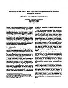
Figure 1.
Time annotation
Delayed preemption
Priorities and events
As commented previously, PREFidy was developed as an execution time estimation and timed simulation tool. As shown in figure 1, in PERFidy [9], the code of each process is divided into segments. Each segment is a piece of code that starts in a channel access and ends in the next channel access. The segment is executed in the simulation in zero time and in one delta cycle. At the same time, its estimated time is obtained. It is represented in figure 1 with small rectangles filled with the “code execution” pattern (in
fact they represent a zero time execution, so they should have no depth). Then, the estimated segment time is inserted in the simulation using a “wait” statement ( ). This method ensures the correct simulation of systems when non-preemptive schedulers are used. In this kind of schedulers, segments between synchronization points are executed without external interferences. However, when considering preemption, several mechanisms used in the design process, especially for the software refinement, do not fulfill these characteristics. This is the case presented in figure 1. This example represents an embedded system with two software tasks. Task 1 does the computation and Task 2 does the I/O communication. For this communication, it uses a blocking function with a timeout. If the data is not provided before this timeout, the process is unblocked and the value is estimated using previous values. Then, Task 2 loads the values in a global variable, and task 1 reads them. In this example, two values have to be obtained and reported to task 1. The first time, the datum does not arrive and the timeout is delivered, and the second time the external datum is provided. Futhermore, Task 2 has a higher priority than Task 1, so when Task 2 is ready to execute, Task 1 is preempted. In general, when a process unlocks a channel, the process that was blocked in that channel can be executed, and depending on their priorities, preemption can be carried out. This preemption can be simulated analyzing the priority of the process unblocked, and deciding which process has to continue. However, when a timeout is delivered, if the priority of the process that is awoken is higher than the priority of the process that is running at that moment, the segment under execution has to be stopped. However, the method of estimation and simulation presented above does not allow this. The segment is completely executed in zero time and the temporal cost is mapped in one step, so intermediate interactions are not possible (for example, at T=55us in figure 1). This means that when the interaction is computed, the segment execution has been done and cannot be modified. Thus, if a global variable is used by both tasks, functional results can also be wrong. If a process is in charge of writing the variable and another process uses these values, the accuracy of the temporal point and, thus, the order in which the accesses are done can be critical. This fact implies that this method cannot simulate the management of communication mechanisms that have no synchronization capabilities, such as global variables. For this reason, global variables are not allowed in this kind of models. However, this restriction can be valid at the system specification level, but may be too restrictive when developing the final software. For instance, if we have to model a peripheral (e.g. a speedometer) and we are going to develop the driver, this problem can appear. It is usual that the peripheral has to be accessed by polling a pointer that provides the peripheral data. Thus, each time the value provided is taken, the current segment is not finished. If the program works with some values obtained from the speedometer in the same segment (with multiple pollingin the same delta cycle), every polling will report the same value. This means that
there is no way to make a correct test of the system (peripheral and driver). Therefore, in these cases, the execution order is not correct. To solve this problem, the code of the task that has to manage the intermediate interaction is always executed when the current task has a smaller priority. To minimize the problem, the time of the preemption is added to the first task at the end of the segment( ), and thus, the simulation partially solves the problem (see figure 1). The interactions of the second task with the rest of the system will be done at the correct time, but for the interaction with the first process of the example, the result is the same as executing the second segment of task 2 at the end of task 1. Summarizing, neither priority management nor asynchronous events, such as interruptions, can be considered. The proposed methodology for system design specifies that every communication needs to be synchronized. However, throughout the refinement process, especially for the software flow, this can be too restrictive. Thus, the methodology has to evolve to accept these elements. The first step to present the solution proposed is to discuss the elements that can be used in the component implementations and that will produce errors in the simulation when using the technology presented above. These errors can appear when a process, which was blocked, is unblocked. The simulator will work correctly if this is caused by an operation done in a channel by the process running in the same processor at that moment. This process will detect that another process is ready, and then the decision of which one has to continue can be taken. However, if this process is not the one which awakes the blocked process, it cannot be solved and new techniques are required. Software timers and alarms can induce a process to pass to the ready state independently of the actions of the running process. They cannot be simulated with the previous technique, but they can be modeled taking into account their predictability. When the timer is set, it is well known when it will be delivered. Thus, when a segment is simulated the preemption can be predicted. The time estimation of the segment is calculated dynamically, so the process execution can be stopped at the exact point when the timer will awake. However, when the process is awoken by an external event, it cannot be modeled in that way. For example, these events can be interruptions or receptions of values in blocking channels. In this case, the event is unpredictable when the segment starts, so the execution cannot be stopped at the right time. IV. ACCURATE MODELING OF GLOBAL VARIABLES The analysis of the current method of simulation presented above shows that modeling preemption in timed simulations with segment time estimations could produce incorrect results. This problem can be tackled in two different ways. On the one hand, it can be interesting to try to obtain a process simulation order as close as possible to the real implementation. On the other hand, we can only ensure data coherency to obtain correct functional results. Thus, we only have to guarantee that read and write
Error
Error
accesses to asynchronous communication mechanisms (such as global variables) are done in the right temporal order. Summarizint the ideas presented in Section III, the problem occurs because the segment code is executed in zero time at the beginning of the segment and, afterwards, the estimation of their temporal cost is applied to the simulation using a wait statement. Thus, certain events (timers or I/O data) that are received during segment executions in the real implementation are executed in parallel with the wait statement in the simulation. This means that the part of the segment, which should be executed after the event, has already been executed. Thus, if the response to the event modifies the values of the variables used by the segment that was previously executed, this simulation may be wrong. The first option is to reduce the part of the segment executed that should be run before the event arrival. The second option avoids the problem because the segment does not use any variable that could be modified by the event response. Just before these shared variables are accessed, the current segment ends and a new one starts with this access. This method allows the execution of the event handler between these two segments and, thus, the value of the variable is correct when used. These two options can be explained with the example in figure 1. Figure 2 shows the real order of execution of the two-process code, the result os simulating with the standard model and the possible solutions. Time (us) REAL PREVIOUS CASE 1 CASE 2 MODEL 0 10 20 Var Var Var 30 Var 40 50 60 70 80 90 Task1-Task2 Task1-Task2 Task1-Task2 Task1-Task2 OK: read OK: read OK: read Error: read after write before write after write after write Executing
Not executing
Write
Read
Figure 2.
Variable Access
Communication using a global variable.
In the real implementation, task 1(T1) starts its execution at t=0us and task 2(T2) is waiting for a timer. The timer is released at t=20us. Then, T1 is preempted and T2 is executed, writing in the variable. After that, T2 is blocked waiting for a new I/O datum. Then, T1 runs again, and reads the value of the global variable. At t=55us the external datum is provided, T1 is preempted and T2 continues its execution. T2 writes the new value in the variable and finishes. Finally, T1 reads it for a second time and the example ends. If the previous simulation model is used, T1 starts the
segment execution at t = 0 ns and finishes at t = 60 us. The segment is completely simulated at the beginning and then the wait statement is executed. Thus, T2 is not actually executed until the segment finishes, so the two interruptions are evaluated at t= 60 us and t = 80 us. The variable is read before the values are stored, so the execution is wrong. Furthermore, the two accesses always obtain the same value, so the process execution cannot be verified because the test bench cannot provide two different values to T1. The first solution presented obtains an execution trace which is as realistic as possible. To do this, we verify each 10 us if there has been an event. Thus, at t=20us the timer expiration is detected, and at t = 60us the external data arrival is captured. Then, T2 executes correctly the first time and nearly the second time. Thus, the functional result is correct and the temporal error is very low. The second solution is to ensure the coherence in the values that are read and written in the variable. This causes the process to be running until t = 35 us. At this time, the variable has to be read, but it is detected that an interruption has been raised. Thus, T2 is executed before the datum is obtained. It is repeated at t = 75us. With this method, the result is also correct. Once the two points of view from where the problem can be tackled has been presented, their implementations, advantages and disadvantages will be discussed. The first approach is based on dividing each segment into several segments to reduce the code executed before event management. For this, a maximum value is defined for the temporal cost of the segments. Then if a segment requires a longer time, it is divided into segments of equal or less duration than the maximum value. This technique ensures that the code executed in the wrong order is limited by a known and adaptable value, and the errors that can appear are minimized. This solution produces a very flexible interval-slicing technique. The maximum interval can vary from a very large interval to a very short one. If the interval is close to the time estimation of the largest segment, the simulation is modified slightly. Only very large segments, where errors are more probable, are divided. This means that the simulation overhead is reduced to a minimum value. If the interval is less than or equal to the temporal cost of the source code basic operations, the simulation is completely modified. The segment concept disappears and each operation is executed in the same simulation time as in the real implementation. Thus, the simulation is very exact and no errors in the execution order can occur. However the simulation overhead is very high. Summarizing, the definition of a maximum interval defines the granularity of the simulation. Apart from the reduction of the error, this method produces execution diagrams that are very close to reality. It also presents three advantages. It is a completely automatic technique. No changes have to be made in the software code. The technique is very flexible, because it is very easy to adapt the simulation to the desired accurate-overhead factor. This method also supports the change of the granularity during the simulation. However, this method presents two disadvantages. First,
it produces an important overhead of the simulation time. The limitation of the maximum segment time means that those segments larger than the limit are subdivided, and thus, the number of segments is increased. Between the end of a segment and the beginning of the next one, the SystemC kernel is executed, and it takes an important time. If the number of segments is increased, the number of kernel executions is higher too and the simulation time increases. Thus, this overhead is proportional to the segment limit value, and better simulations require longer times. Task Priority
T= 0
Simulation time
∆ T= 0 ∆ T= 10 ∆ T= 0 ∆ T= 10
T=10 T=20
1 1
Task Priority
Estimation
∆ T= 10 Prediction Expected preemption
T=30
∆ T= 0 ∆ T= 10
T=40 T=50
∆ T= 0 ∆ T= 10 ∆ T= 10
T=60 T=70
∆ T= 0 ∆ T= 10 ∆ T= 0 ∆ T= 10
T=80 T=90
∆ T= 10
2 2 Events Predictable: Timeout expiration T=20
∆ T= 10 Unpredictable: Hardware interrupt T=55
∆ T= 10 Delayed preemption ∆ T= 10
has to be placed every time an asynchronous communication is done. This need can cause coding errors because it is easy to forget to introduce a mark. Because of this, the technique is not completely satisfactory. However it can be useful to ensure the correct simulation of critical points of the code, providing an alternative to the first solution presented. Using this method, not all simulation is adapted to the required granularity, limiting the maximum errors in the time the tasks are executed, however, if only a few critical points are actually interesting for this timing analysis, it is a better solution. Furthermore, this method increases the simulation time significantly. The second option is the redefinition of these global variables as a new kind of channels. Then, every channel access can be done in the correct time. Furthermore, this solution guarantees the support of the orthogonality of communication and functionality, with the advantages that this provides. The technique completely solves the problem of the coherence of global variable values with minimum modifications in the source code and without a notable simulation overhead. To implement this, a new channel has to be provided. This channel has the same behavior as a common variable, but every read and write access makes the current segment finish and the time is annotated. Thus, the access is done at the beginning of a new segment, and therefore, in the exact temporal point. Solution 1:
Solution 2:
Global code: int glob_var;
Global code: GLOBAL_VAR(glob_var)
Handler: ... PLACE_IN_TIME glob_var = *(int*)0x1000; …
Handler: ... glob_var = *(int *)0x1000; …
Process: ... PLACE_IN_TIME local_var=glob_var; …
Process: ... local_var=glob_var; …
Time (us) Code execution
Figure 3.
Time annotation
Delayed preemption
Time-slicing technique
The other disadvantage is more critical. This method does not ensure the coherence in the variable values. The segment limitation reduces the probability of the inversion of read and writes accesses, but it does not always eliminate the problem. Depending on the value of the time segment limit, the simulation can be correct or not. To ensure the correct access order to the variable, the other method presented at the beginning of the section is needed. This method obliges the simulation to end the segments before accessing the global variables. Then, the occurrence of an external event is checked, and, in that case, the preemption can be simulated, and the preempted process does not read the variable until the event reaction has finished. This means that the variable could be written before the read access is done. Thus the simulation is correct. However, the similarity of the task simulation flow and the real execution times may not be as good as in the previous method. To implement this method, two possibilities are proposed. The first one is to define a mark that has to be inserted in the source code to enforce the end of the segments where global variables are used. Placing this mark just before the accesses, the communication points that are not synchronized can be correctly modeled. This technique presents the disadvantage that the mark
Figure 4.
Global variable management.
With these three solutions the problem of modeling asynchronous events in software components with priorities and preemption scheduling is solved. These solutions are independent of the method used to implement the model of the rest of characteristics of the environment where the components will be executed. V. RESULTS These three solutions have been implemented in PERFidy[9], and the results obtained are as expected. About functionality, the use of the solutions proposed, specially the
last one, avoids all problems caused by the use of nonsynchronized communication. The most important numerical result obtained in this work is the relationship between the maximum segment time defined in the first solution and the overhead in the simulation time. To obtain this, a model of a GSM coder[11] described in SystemC has been used. From this example, and once the suitable platform parameters are applied to the library, the average value of the segment times has been found to be of the order of hundreds of nanoseconds. The longest segments are of the order of some milliseconds. Therefore, to obtain good results, interval limits from 100 ms to 10 ns have to be tested. This range will analyze the overhead form the case where no segments are subdivided to the case where all segments are modified. The following results have been obtained: Time-slice Original PERFidy 100ms 1 ms 10us 1us 100ns
Simulation Time 1.45 sec 1.52 sec 1.68 sec 2.47 sec 10.89 sec 74 sec
Table 1: Time-slice interval vs simulation time. This result shows that the time increment increases exponentially. This is because the segment time distribution is also exponential. This result confirms that this is not the most suitable way to obtain the coherency in asynchronous communication, because this requires very short segments and then the simulation is very slow. However, it will be useful to obtain better execution graphs, because the most important errors are in the longest segments, and these can be estimated more accurately with minimum overhead. The comparation of time cost between PERFidy simulation and other simulation mechanisms has been presented in [9]. However, the comparation of the effect of the mechanisms presented in this paper with other models is difficult because preemption is usually not supported in that way. VI. CONCLUSION In the development of real-time, embedded systems (RT/E), the close relationship between hardware and software necessitates the use of design methodologies where systems can be developed as a whole, especially for hardware dependent software (HdS). The platform where the system will be implemented has to be adequately modeled to obtain an optimum design. Thus, both timing estimation techniques and modeling operating system features are key elements for software component development. Mechanisms provided by SystemC are suitable for specification and hardware development steps, however, for software refinement, there is a lack of features that has to be overcome. In this context, modeling priorities and other scheduling
characteristics, such as preemption, at the same time as temporal simulations based on segment techniques are used, requires an accurate modeling of the events that are unpredictable before the simulation starts. In this paper, asynchronous events have been suitably handled, independently of the method used to model priorities or temporal costs. One technique is based on the definition of a maximum interval of time for code blocks that are analyzed as a single element. This technique is useful to obtain timing analysis of task flows, but not to ensure the coherence of global variables. Furthermore, when the time limit is reduced, the simulation overhead is very important. To guarantee the correct use of asynchronous communications, another two methods are proposed. The first one is based on the manual insertion of marks that oblige executing the accesses at the correct time. This technique has the disadvantage that many code modifications can be needed, and thus it is error prone. However, it can also be used as a complement to the first technique. The last technique is based on the identification of this global variables and their redefinition as channels. This method is more effective than the previous one and ensures the coherency of values with a minimum overhead. REFERENCES [1] “International Technology Roadmap for semiconductors, 2003 Edition: Design”, http://public.itrs.org. [2] A. Sangiovanni-Vincentelli and G. Martín: “Platformbased design and software design methodology for embedded systems”, IEEE Design and Test of Computers, November-December, 2001. [3] G. Martín and F. Schirrmeister: “A design chain for embedded systems”, IEEE Computer, March, 2002. [4] S. Yoo and A. Jerraya: “Introduction to hardware abstraction layers for SoC”, proc. of DATE’03, IEEE, 2003. [5] T. Grötker, S. Liao, G. Martín and S. Swan, “System Design with SystemC”, Kluwer, 2002. [6] L. Benini, D. Bertozzi, D. Bruni, N. Drago, F. Fummi and M. Poncino: “ SystemC cosimulation and emulation of multiprocessor SoC designs”, IEEE Computer, April, 2003. [7] S. Yoo, I. Bacivarov, A. Bouchima, Y. Paviot and A. Jerraya: “Building fast and accurate SW simulation models based on hardware abstraction layer and simulation environment abstraction layer”, proc. of DATE’03, IEEE, 2003. [8] A. Gerstlauer, H. Yu and D.D. Gajski: “RTOS modeling for system-level design”, ”, in A. Jerraya, S. Yoo, D. Verkest and N. Wehn (Eds.), Embedded Software for SoC, Kluwer, 2003. [9] H. Posadas, F. Herrera, P. Sánchez, E. Villar and F. Blasco. “System-level performance analysis in SystemC”. Proc. of DATE, IEEE, 2004 [10] F. Herrera, V. Fernández, P. Sánchez and E. Villar. Chapter "Embedded Software Generation from SystemC for Platform Based Design" of "SystemC Methodologies and Applications", Kluwer Academic Publishers. 2003-01 [11] EN 301.245, ETSI, December, 1997.