Calibration techniques for projector-based displays typ- ically require that the display configuration remain fixed, since they are unable to adapt to changes such ...
Real-Time Projector Tracking on Complex Geometry Using Ordinary Imagery Tyler Johnson and Henry Fuchs Department of Computer Science University of North Carolina Chapel Hill Abstract Calibration techniques for projector-based displays typically require that the display configuration remain fixed, since they are unable to adapt to changes such as the movement of a projector. In this paper, we present a technique that is able to automatically recalibrate a projector in real time without interrupting the display of user imagery. In contrast to previous techniques, our approach can be used on surfaces of complex geometry without requiring the quality of the projected imagery to be degraded. By matching features between the projector and a stationary camera, we obtain a new pose estimate for the projector during each frame. Since matching features between a projector and camera can be difficult due to the nature of the images, we obtain these correspondences indirectly by first matching between the camera and an image rendered to predict what the camera will capture.
1. Introduction Research in adaptive projector displays has enabled projection on display surfaces previously thought impractical. Raskar [16] and Bimber [3] describe general methods of correcting for the geometric distortions that occur when non-planar surfaces are used for display. Other work [2, 10, 13] has focused on eliminating the need for high-quality projection screens by compensating for the color and texture of the display surface. These techniques and others have greatly increased the versatility of the projector and brought us closer to a “project anywhere” display. Recently, the focus has begun to shift towards robust automatic calibration methods [1, 15, 17] that require little or no interaction on the part of the user. Within this category are techniques that can perform calibration while user imagery is being projected. This allows display interruption to be avoided in the event that the display configuration changes, e.g. a projector is moved. These “online” auto-calibration techniques can be divided into two categories. In the first are the active techniques where calibration aids that are imperceptible to a hu-
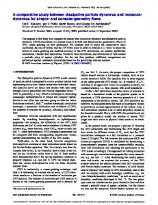
Figure 1. Our tracking process adapts to changes in projector pose, allowing ”on the fly” display reconfiguration.
man observer are injected into the user imagery. Cotting et al.[5, 6] embed these imperceptible calibration patterns in the projected imagery by taking advantage of the micromirror flip sequences used to form images in DLP projectors. Image intensity is modified slightly at each pixel so that a camera exposed at a small frame interval will capture the desired calibration pattern. This technique currently requires that a portion of the projector’s dynamic range be sacrificed, leading to a slight degredation of the user imagery. The second type of auto-calibration technique does not rely on the use of calibration aids and instead attempts to extract calibration information from the user-projected imagery itself. In Yang and Welch [20], features in the user imagery are matched between a pre-calibrated projector and camera and used to automatically estimate the geometry of the display surface. This technique leaves the user imagery unmodified, but relies on the presence of features in the user imagery that are suitable for matching. To our knowledge, no existing work has demonstrated the ability to continuously track a projector in real-time on complex display surface geometry without modifying the projected imagery or using fixed fiducials. In addition to
allowing dynamic repositioning of the projector during display, such a system could also be used for projector-based augmentation. Here, a hand-held projector can be used to augment objects with information or to alter their appearance [17, 18]. This effectively allows a projector to be used as a graphical “flashlight” where the projector can be controlled directly by the user to create imagery on previously unlit portions of a surface or to enhance image detail by moving the projector closer to the surface. In this paper, we describe a technique that enables such a system. By matching features between the projector and a stationary camera, we re-estimate the pose of the projector continuously. Since matching features between a projector and camera directly can be difficult, we propose obtaining these correspondences indirectly by first matching between the camera and an image generated to predict what the camera will capture. We present a simple radiometric model for generating this predicted image. Our technique does not affect the quality of the projected imagery and can be performed continuously without interrupting the display.
2. Predictive Rendering for Feature Matching Given a static camera of known calibration, where the depth at each camera pixel is also known, a set of image correspondences between the camera and a projector indirectly provides a set of 2D-3D correspondences in the projector, allowing the calibration of the projector to be determined. Unfortunately, there are a variety of factors that complicate the process of matching between projector and camera images as seen in Figure 4. Some of these complications include 1. differences in resolution, aspect ratio and bit-depth 2. large camera-projector baselines 3. radiometric effects e.g. projector/camera transfer function and surface BRDF present in camera image, but not in projector image
To avoid these problems, we instead perform matching between an actual image captured by the camera and a prediction of this captured image generated using graphics hardware. We will refer to the image sent to the projector as the projected image, the image captured by the camera as the captured image, and the prediction of the captured image as the predicted image. Since the displacement of a projector within a single frame is small, geometric differences between the predicted and captured images will be small as well. Also, by generating a predicted image that takes into account the radiometric properties of the display, the captured and predicted images will be similar in intensity, leading to better matching results. By reversing the process used to generate the predicted image, we can map features in the predicted image to
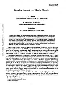
Figure 2. Mapping projector pixels to camera pixels.
their original locations in the projected image to obtain 2D3D correspondences allowing us to calibrate the projector.
2.1. Geometric Prediction The first step in generating the predicted image is to determine the mapping from projector pixels to camera pixels. This allows us to warp the projected image into the frame of the camera as if it had observed the projected imagery. This mapping is completely defined by the calibration of the projector and camera and the geometry of the display surface and is the same process needed to determine the required warping to compensate for the display surface geometry when displaying a desired image to a viewer. In the case of generating the predicted image, we map between projector and the camera instead of between the projector and the viewer. We accomplish the warping between the camera and projector using the second pass of the two-pass rendering technique proposed by Raskar [16]. Using the projection matrix of the projector, we project the texture coordinates of the projected image onto the display surface geometry and render it using the projection matrix of the camera. An illustration of this process is provided in Figure 2.
2.2. Radiometric Prediction As Tables 1 and 2 show, incorporating a radiometric simulation into the generation of the predicted image can result in an immense improvement in feature matching performance, especially for rendered imagery. The radiometric model we use assumes that the projector can be reasonably approximated as a point light source, which implies that each point on the display surface receives illumination from only one direction. We will additionally assume a display surface with a uniform, diffuse BRDF since this type of surface is commonly used for projective display. We also ignore any contribution to the captured image from indirect
illumination. For a point X on the display surface, we will denote its projection in the camera and projector images as xc and x p . Given one of the these points, the locations of the other two are easily determined using the calibration of the camera and projector and the model of the display surface. The radiometric value measured by a camera sensor is irradiance, the amount of energy per area. The irradiance within a sensor pixel is integrated over time to produce the sensor’s output. A pixel’s intensity value in the final image may however be a non-linear function of the sensor output. The goal of our radiometric simulation is then to predict the irradiance arriving at each camera pixel and apply the transfer function of the camera, also called its input-output response function or simply response. Let Rc be the response function of the camera and E (xc ) the irradiance at a camera pixel xc . The intensity in the captured camera image Mc (xc ) is then Mc (xc ) = Rc (E (xc )) .
(1)
The irradiance at a point on the camera sensor is a function of the scene radiance, the energy per area per solid angle of the source. Assuming a small aperture and a thin lens, the irradiance E (x) at a point x on the camera sensor is directly proportional to the scene radiance L arriving at x [9]. Specifically, this proportionality is E (x) = L
π cos4 θ , 4 n2
(2)
where n is the f-number of the lens and θ is the angle between the normal of the sensor plane and the unit vector from x to the center of the lens. This equation indicates a variation in the proportionality between scene radiance and sensor irradiance over the camera’s field-of-view. We have found this variation to be negligible and instead use the simplification ! −→" E (xc ) = αL X, XC ,
(3)
! −→" where L X, XC is the radiance at X in the direction of the camera center!C, and " α is some constant. −→ The value of L X, XC is the result of illumination from the projector being reflected by the display surface towards the camera and depends on the surface BRDF. Since we consider the projector to be a point light source, the point X receives illumination only along the direction from the −→ projector center XP. This, combined with the assumption of a uniform, diffuse surface, leads to ! −→" ! −→" L X, XC = ρE X, XP ,
(4)
! −→" where E X, XP is the incident irradiance at X due to the projector and ρ is the surface BRDF. The incident irradiance at a surface point due to a point light source depends on the radiant intensity of the light source in the direction of the surface point, the orientation of the surface normal with respect to the incoming di! light −→" rection, and the distance to the light source. If I P, PX is the radiant intensity of the projector in the direction of point X, then ! −→" ! −→" cos (θ ) E X, XP = I P, PX , r2
(5)
! −→" I P, PX = S (x p ) [R p (M p (x p )) · [Ir , Ig , Ib ]] ,
(6)
where θ is the angle between the surface normal at X −→ and the direction XP and r the distance between X and the projector. −→ We model the radiant intensity I(P, PX) as a function of the intensity of the projected image at pixel x p , M p (x p ) = [r, g, b] ∈ [0, 1]3 , and the response function R p of the projector such that
where Ir..b are the maximum radiant intensities of the red, green and blue color channels of the projector and S ∈ [0, 1] is a per-pixel attenuation map. The purpose of S, which we refer to as the projector intensity profile, is to model changes in brightness over a projector’s field-of-view due to effects such as vignetting. Combining the above equations, the final intensity value measured at each camera pixel as a function of the intensity at its corresponding location in the projected image is #
& %% $ $ cos(θ ) Mc (xc ) = Rc , S(x p ) R p (M p (x p )) · I r , I g , I b r2 (7) where we have combined α, ρ and the Ir..b into the terms I r..b . Since the field-of-view of each camera pixel may encompass more than a single projector pixel, we filter the projected image to obtain an average intensity value that we use to evaluate Equation (7).
3. Calibration In this section, we describe our process of calibrating the geometric and radiometric parameters necessary to apply the technique we use to generate the predicted image.
3.1. Geometric Calibration We accomplish initial geometric calibration in an upfront step by observing projected structured light patterns
with a stereo camera pair. This process yields a set of correspondences between the projector and camera pair that allows us to reconstruct the geometry of the display surface and calibrate the projector. Raskar provides a thorough discussion of this process in [16]. To obtain an accurate model of our room-like display surface as seen in Figure 2, we use the RANSAC-based plane fitting technique introduced by Quirk [14]. Any other reconstruction method that gives a geometric description of the surface could also be used.
3.2. Radiometric Calibration In addition to the geometric calibration, generation of the predicted image requires estimation of the projector and camera response, the projector intensity profile, and the terms I r..b . Since these are intrinsic properties, they can be calibrated once in an up-front process and then used in arbitrary geometric configurations. Since we use the stereo camera pair for geometric calibration, out of convenience, we also use one of these cameras for projector tracking. To prevent indirect scattering from affecting the results, we perform radiometric calibration by projecting on a portion of the display surface that produces low levels of these effects. In our case, we project onto a single plane and use our geometric calibration process to establish the geometric relationship between the camera, projector and display surface. 3.2.1
Projector Response
The first step in our radiometric calibration process is to calibrate the projector response. We accomplish this manually by projecting an image where half the image is filled with some intensity I and the other half with a dither pattern computed using error-diffusion dithering [8] to have a certain proportion of black and full intensity pixels. By adjusting the proportion of black and white pixels such that the intensity of the image appears consistent throughout, we can determine what proportion of the projector’s maximum output intensity the intensity I represents. This is done for a number of intensities and the resulting data points are interpolated with a spline to reconstruct the response function of the projector. 3.2.2 Intensity Profile We recover the intensity profile of the projector by projecting a sequence of solid grayscale images of increasing intensity. To remove the effect of projector response on the captured camera images, we linearize the output of the projector during this step using the inverse of the projector response. At each pixel in a captured camera image, we have
υ(xc ) =
r2 R−1 c (Mc (xc )) = S(x p )[M p (x p ) · [I r , I g , I b ]]. (8) cos(θ )
The value of υ at each camera pixel can be evalutated given the response function of the camera. Since we have linearized the projector response when projecting the sequence of grayscale images, we can use the captured camera images to get a rough estimate of the camera response. We do this by finding the median intensity value in each camera image and use this as the camera response for the grayscale intensity of the projected image. In the next section, we will describe our technique for refining the camera response estimate. Next, we compute υ(xc ) at each pixel of the camera images. Let xm be the pixel in an image where the maximum value of υ occurs. Dividing the value of υ at each pixel by υ(xm ) gives the relation S(x p ) cos(θm )r2 R−1 c (Mc (xc )) = , 2 R−1 (M (x )) S(x pm ) cos(θ )rm c c m
(9)
with subscript m indicating values for pixel xm . The M p (x p ) · [I r , I g , I b ] terms in both the numerator and denominator cancel since the projected image was uniform in intensity. Because υ(xm ) is a maximum in the camera image, S(x pm ) = 1, and we can compute an estimate of the intensity profile of the projector at each pixel using a single camera image. Since the computed intensity profile may vary between images, we use the average of the intensity profiles extracted from each image as our final estimate. It is important in this step to exclude camera images containing saturated pixels, which will affect the computation of the intensity profile. We also blur the extracted profile with a small gaussian kernel to remove noise. 3.2.3
Projector Brightness and Camera Response
The remaining terms to be calibrated are the I r..b and the refinement of the camera response. The process we use for calibrating the camera response is based on the technique described in Debevec [7]. In addition to the grayscale images used to calibrate the intensity profile of the projector, we also project a series of solid color images of different intensities, linearizing the output of the projector as we did before. From Equation (7), at each pixel in a camera image taken of one of these solid color images, we have a linear equation in the I r..b and one of the 256 discrete values that form the domain of R−1 . If the projected intensity is (r, g, b) and the intensity measured by the camera at some pixel is i, we have srI r + sgI g + sbI b − R−1 c (i) = 0,
(10)
) where s = cos(θ S(x p ). r2 −1 Let gi = R (i) and let zk be a vector of length 256 composed of all zeros except that it contains the value 1 at the location corresponding to the intensity value measured by the camera in the kth equation. The system of equations can then be put into matrix form as
s1 r1 s2 r2 sn rn
s1 g1 s2 g2 .. .
s1 b1 s2 b2
sn gn
sn bn
z1 z2 zn
Ir Ig Ib g1 .. .
g256
=
0 .. . . 0
(11)
This system can be efficiently solved using SVD to produce the best solution vector in the least-squares sense. In practice, it may be possible that no camera pixel of a certain intensity can be found in any of the camera images. In this case, the values of R−1 c for which data exists can be calibrated and then interpolated to produce the missing values. To enforce smoothness between the gi s, we also add a second derivative term to Equation (11) of the form λ (gi−1 − 2gi + gi+1 ) where λ can be used to control the smoothness. Since the solution vector is only defined up to an arbitrary scale and sign, we choose the sign such that the solution vector is positive and the scale such that the gi lie in the range [0, 1]. The response function of the camera is easily obtained by inverting the gi s. In our testing, we captured images of 17 different intensities each of red, green, blue, and yellow. In choosing the camera image pixels we use as contraints in Equation (11), we have created an automated process that selects pixels uniformly across color, intensity, and image location. 3.2.4 Error To estimate the error in our calibration and validate our model, we used the calibration to predict the camera images used in calibrating the projector intensity profile. Comparing the predicted images to the actual camera images, we found the overall average error to be just under 4 camera intensity values.
4. Rendering We implemented our radiometric model in a real-time GPU pixel shader that allows predicted images to be produced at interactive rates. The shader takes as input all of the radiometric parameters with the projector and camera response stored as 1D textures and the intensity profile stored as a 2D texture. The geometric parameters are two 2D floating-point textures called the geometry and normal
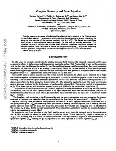
map, which store the (x, y, z) position and normal of the display surface at each camera pixel. The projection matrix of the projector and its center-of-projection are also input parameters. To predict the intensity measured by the camera at each pixel, the shader program first estimates the average color of the projected image pixels that fall within the extent of each camera pixel. At each predicted image pixel, we look up the display surface vertex X in the geometry map and project it into the projected image using the projector calibration to obtain a texture coordinate. We repeat this process at three neighboring pixels, allowing us to compute two derivative vectors indicating the size of the region in the projected image that should be filtered. We pass this information to the texture mapping hardware, which filters the projected image and the intensity profile using a kernel of the appropriate size. We next apply the projector response to the filtered color by performing a per channel look-up in the projector response texture. Using the center-of-projection of the projector and the value of X, the value of r2 for the pixel is easily computed. To compute the value of cos(θ ), we look up the display surface normal in the normal map and take the dot product of the normal and the unit vector from X to the projector center. Composing the rest of the model terms together, we do a final look-up in the camera response texture to get the final predicted intensity for the pixel. The shader program then returns the predicted intensity in one color channel of the predicted image with the other two channels left black. This allows us to read back the predicted image to the CPU as a single channel texture, greatly improving read-back efficiency. Figure 3 shows a captured camera image and a predicted image rendered using our technique. We computed the difference between these images to be 15.1 intensity levels on average per pixel with a standard deviation of 3.3. The images appear very similar, with the most significant difference being the higher contrast in the rendered image. The rendered image is also slightly darker. We attribute both of these differences to indirect scattering effects caused by the complex display surface geometry being present in the camera image, but not reproduced in the predicted image.
5. Continuous Projector Calibration To track the projector motion in real-time using the predicted image, we first detect a set of features in the captured camera image during each frame. As described previously, by matching features between the captured image and the predicted image, we indirectly obtain a set of 2D3D point projector point correspondences that allows us to estimate the pose of the projector. For feature detection in the captured image, we use Intel’s OpenCV library implementation of the feature detection algorithm introduced by
Figure 3. An actual image captured by a camera (left) and a rendered prediction of the camera image (right).
Shi and Tomasi [19]. To obtain correspondences for the detected features in the predicted image, we use pyramidal Lucas-Kanade tracking [12, 4], also part of OpenCV. To transform these correspondences into 2D-3D projector point correspondences, we use the same geometry map used in rendering the predicted image, which stores the mapping between camera pixels and 3D points on the display surface. To obtain the 3D correspondences, we perform a look-up in the geometry map for each feature in the captured image. To obtain the 2D correspondences for these points, we reverse the mapping from projected image pixels to predicted image pixels. This is done by consulting the geometry map using the feature locations in the predicted image and projecting the resulting points into the projected image using the projector calibration.
5.1. Pose Estimation We assume that any motion of the projector does not affect its intrinsic calibration, requiring only the 6 parameters comprising the extrinsic calibration (position and orientation) to be re-estimated. To calculate the projector pose from the 2D-3D correspondences, we use a common technique from analytic photogrammetry described in Haralick [11]. The technique takes as input a set of 2D-3D correspondences as well as an initial estimate of the pose and minimizes the sum of squared reprojection errors using a nonlinear least-squares technique. While the need for an initial guess is a limitation of the technique, it has the advantage of being able to compute the correct pose in situations where a linear technique will fail, such as when all 3D correspondences are coplanar. We have found that using the previous pose of the projector as an initial guess for the current pose is adequate for convergence even when the projector pose is changing rapidly.
5.2. Outliers We have found it essential to incorporate RANSAC into the pose estimation to prevent false correspondences from affecting the pose estimation results. In our RANSAC approach, we estimate the projector pose using three correspondences selected at random and record the number of correspondences whose resulting reprojection error is less than 10 projector pixels as inliers. We perform this iteration repeatedly until there is a 99% chance that at least one interation has chosen a set of three correct corrspondences. We then take the largest inlier set over all iterations and perform a final pose estimate.
5.3. Filtering Since we do not synchronize the projector and camera, it is possible for the captured and predicted images to be out of step by a frame. This introduces error into the correspondences used to calibrate the projector and can lead to instability if the pose estimates are not filtered. In our experimentation, we have found that by limiting the amount of change that is made to the pose estimate each frame, any instability caused by an unsynchronized camera and projector can be removed. After the change in pose has been calculated, we add it to the current pose estimate at 10% of its original scale. We have found this to ensure tracking stability while still providing a responsive system.
6. Results We tested the tracking ability of our system using two dynamic applications. The first application displays a rotating panorama of a real environment and contains many strong features. The second application is a virtual flight simulator that displays rendered 3D geometry and is relatively sparse in strong features.
a)
b)
c)
d)
Figure 4. a) An image captured by a camera. b) An image rendered to predict the captured image. c) The projected image that was captured. d) A contrast-enhanced difference image of the captured and predicted images.
Imagery Panorama(front) Panorama(back) Flight Simulator
Avg. Feature Count 191 197 36
Avg. % Inliers 81 84 60
Imagery Panorama(front) Panorama(back) Flight Simulator
Avg. Feature Count 183 192 13
Avg. % Inliers 38 46 30
Table 1. Feature matching performance using both geometric and radiometric prediction of the captured image.
Table 2. Feature matching performance using only geometric prediction of the captured image.
To test the feature detection and matching capability of the system, we recorded the number of features successfully
matched between the predicted and camera images and the number of these matches found to be correct by RANSAC in each frame. Table 1 shows the results we collected over 1000 frames for both applications. The maximum number of features to detect and match was limited to 200 for this experiment, which we have found to be more than adequate for tracking. While the results are considerably better for the panorama application, we were not able to notice a visible difference in the quality of the tracking results. This is due to the lower number of matched features in the flight simulator being sufficient to accurately calculate the projector pose and the success of RANSAC in removing the incorrect correspondences. To estimate the improvement in feature matching gained by performing radiometric prediction, we ran the same tests using predicted images generated using only geometric pre-
diction. The predicted images were converted to grayscale using the NTSC coefficients for color to grayscale conversion. The results of this experiment are present in Table 2. Note that during this experiment, tracking for the flight simulator was lost after only 6 frames. The performance of the tracker is heavily dependent on the number of features that the system attempts to detect and match each frame. Setting the maximum number of features to detect and match at 75, we were able to obtain excellent tracking results and measured the performance of the tracker to be approximately 27 Hz for both applications.
7. Summary and Future Work We have described a new technique that enables a projector to be tracked in real-time without affecting the quality of the projected imagery. This technique allows dynamic repositioning of the projector without display interruption. By matching features between the projector and a static camera, the pose of the projector is estimated each frame. Since obtaining correspondences between the projector and camera can be difficult, we obtain these correspondences indirectly by matching between the camera image and an image rendered using the current calibration information to predict the image the camera will capture. We describe a simple radiometric model that can easily be implemented on graphics hardware to produce this predicted image. Our current technique has certain limitations we would like to overcome in future work. Our radiometric calibration process currently requires a uniform display surface albedo and that there be a portion of the display surface to project on that does not introduce substantial indirect scattering effects. A futher limitation is the reliance on the presence of features in the user imagery that are suitable for matching. We believe, however, that exposing the camera for a short frame interval will expose additional features in the user imagery when using a DLP projector since small differences in intensity can be magnified greatly by the mirror flips that occur.
8. Acknowledgements The authors wish to thank Herman Towles and Rick Skarbez for their insights and suggestions on this paper.
[4]
[5]
[6]
[7]
[8]
[9] [10]
[11] [12]
[13]
[14]
[15]
[16]
[17]
[18]
References [1] M. Ashdown, M. Flagg, R. Sukthankar, and J. Rehg. A flexible projector-camera system for multi-planar displays, 2004. [2] O. Bimber, A. Emmerling, and T. Klemmer. Embedded entertainment with smart projectors. IEEE Computer, 38(1):56–63, 2005. [3] O. Bimber, G. Wetzstein, A. Emmerling, and C. Nitschke. Enabling view-dependent stereoscopic projection in real en-
[19]
[20]
vironments. In 4th IEEE and ACM International Symposium on Mixed and Augmented Reality, pages 14–23, 2005. J.-Y. Bouguet. Pyramidal implementation of the lucas kanade feature tracker description of the algorithm. In Technical Report, Intel Corporation, 1999. D. Cotting, M. Naef, M. Gross, and H. Fuchs. Embedding imperceptible patterns into projected images for simultaneous acquisition and display. In International Symposium on Mixed and Augmented Reality, pages 100–109, 2004. D. Cotting, R. Ziegler, M. Gross, and H. Fuchs. Adaptive instant displays: Continuously calibrated projections using per-pixel light control. In Eurographics, pages 705–714, 2005. P. E. Debevec and J. Malik. Recovering high dynamic range radiance maps from photographs. Computer Graphics, 31(Annual Conference Series):369–378, 1997. R. W. Floyd and L. Steinberg. An adaptive algorithm for spatial grayscale. Journal of the Society for Information Display, 17(2):75–77, 1976. D. A. Forsyth and J. Ponce. Computer Vision A Modern Approach. Prentice Hall, 1st edition, 2003. M. D. Grossberg, H. Peri, S. K. Nayar, and P. N. Belhumeur. Making one object look like another: Controlling appearance using a projector-camera system. In IEEE Computer Vision and Pattern Recognition, volume 1, pages 452–459, 2004. R. Haralick and L. Shapiro. Computer and Robot Vision, volume 2. 1993. B. Lucas and T. Kanade. An iterative image registration technique with an application to stereo vision. In Proceedings of Imaging Understanding Workshop, pages 121–130, 1981. S. K. Nayar, H. Peri, M. D. Grossberg, and P. N. Belhumeur. A projection system with radiometric compensation for screen imperfections. In ICCV Workshop on ProjectorCamera Systems (PROCAMS), October 2003. P. Quirk, T. Johnson, R. Skarbez, H. Towles, F. Gyarfas, and H. Fuchs. Ransac-assisted display model reconstruction for projective display. In Emerging Display Technologies, 2006. A. Raij and M. Pollefeys. Auto-calibration of multi-projector display walls. In International Conference on Pattern Recogniton, 2004. R. Raskar, M. S. Brown, R. Yang, W.-C. Chen, G. Welch, H. Towles, W. B. Seales, and H. Fuchs. Multi-projector displays using camera-based registration. In IEEE Visualization, pages 161–168, 1999. R. Raskar, J. van Baar, P. Beardsley, T. Willwacher, S. Rao, and C. Forlines. ilamps: Geometrically aware and selfconfiguring projectors. In ACM SIGGRAPH, 2003. R. Raskar, G. Welch, K.-L. Low, and D. Bandyopadhyay. Shader lamps: Animating real objects with image-based illumination. In Eurographics Workshop on Rendering, 2001. J. Shi and C. Tomasi. Good features to track. In IEEE Conference on Computer Vision and Pattern Recognition (CVPR’94), Seattle, June 1994. R. Yang and G. Welch. Automatic and continuous projector display surface estimation using every-day imagery. In 9th International Conference in Central Europe on Computer Graphics, Visualization and Computer Vision, 2001.