real-time trajectory generation in Python, from a PC with ... for testing and prototype development. ... manufacturing automation, and all laboratory projects in-.
Real-Time Robot Trajectory Generation with Python* Morten Lind1 , Lars Tingelstad1 and Johannes Schrimpf2
Abstract— Design and performance measurements of a framework for external real-time trajectory generation for industrial robots is presented. The framework is implemented entirely in Python. It serves as a proof of concept for performing real-time trajectory generation in Python, from a PC with connection to the motion controller in an industrial robot controller. Robotic applications requiring advanced, custom trajectory generation, and a high level of integration with sensors and other external systems, may benefit from the efficiency of Python in terms of reduced development time, lower code complexity, and a large amount of accessible software technologies. The presented framework, dubbed PyMoCo, supplies a set of simple trajectory generators, which are comparable to those found in contemporary industrial robot controllers. Designing and implementing new trajectory generators and integrating or extending the included trajectory generators is central to the design of PyMoCo. Laboratory applications involving real-time sensor- and vision-based robot control has demonstrated the usability of PyMoCo as a motion control framework and Python as a robotics application platform. For robotics applications with a control frequency not exceeding a couple of hundred Hz, computation deadlines no shorter than some couples of milliseconds and jitter tolerance at the order of a millisecond, PyMoCo may be considered a feasible and flexible framework for testing and prototype development.
I. I NTRODUCTION Robotic tasks of limited complexity such as simple positioning tasks, trajectory following or pick-and-place applications in well structured environments, are straightforward to develop and integrate in the application platform of the native robot controller using current commercial robot control software (de Schutter, et al. (2007) [1]). If robots communicate or interact with other robots or systems, the implementation is most often based on vendorspecific proprietary protocols and with limited performance specifications that preclude online sensor-based control (Decré (2010) [2]). However, there is a strong market pull for more flexible and cost effective robotic systems which are able to integrate a multitude of sensors and operate in unstructured environments. An example of this is the increased use of industrial robots in small and mediumsized manufacturing enterprises, often characterized by a combination of low-volume, high variety, and custom-made *The work presented has been financially supported by the The Research Council of Norway through the research programmes “SFI Norman”, “BIA Robust, industriell sømautomatisering” and “KMB Next Generation Robotics”. 1 Department of Production and Quality Engineering, Norwegian University of Science and Technology, Trondheim, Norway 2 Department of Engineering Cybernetics, Norwegian University of Science and Technology, Trondheim, Norway e-addresses: {morten.lind, lars.tingelstad,
johannes.schrimpf} at ntnu.no
goods (EURON (2005) [3]). In order to meet these requests from the industry, new methods for programming and system integration are needed. Many research laboratories therefore attempt to circumvent the application platform of the native robot controller, which either precludes real-time interaction or does not offer an appropriate set of technologies for solving the pertinent problem, in order to directly interface the motion control level. The motion control level is described as the entity providing a real-time interface for addressing the joint configuration space of the robot arm at an intermediate-level frequency; in the range from 100 Hz to 1 kHz. The ability to address the motion control level from an external application platform may thus give full control of choosing hardware peripherals, programming software and control algorithms (Decré (2011) [2]). The motion control level is often referred to as low-level control in literature. A. Related Work Applications that utilize low-level interfaces, to the motion control level, are usually implemented with compiled, intermediate-level languages, such as C or C++, and deployed on some real-time operating system (OS) platform, such as VxWorks, QNX, OS-9 and RTAI+Linux. The obvious reasons for these choices are among requirements to hard real-time performance; efficiency of computation with short cycle times; and latency tolerance on the time scale of microseconds. Dallefrate et al. (2005) [4] used RTAI+Linux to control the Mitsubishi PA10 robot at the motion control level in 1 kHz over Arcnet. Kubus et al. (2010) [5] modified Stäubli controllers and gained external joint level position control rates of 10 kHz and 250 Hz from a QNX system on a standard PC. Buys et al. (2011) [6] present a teleoperation setup using two KUKA Light-Weight Robots (LWR) coupled to a Willow Garage Personal Robot (PR2). The two KUKA LWR robots are controlled over the KUKA Fast Research Interface (FRI) (Schreiber et al. (2010) [7]) for the KUKA KRC2LR industrial controller from an external control unit running RTAI+Linux. The communication is based on the UDP protocol and has a configurable communication rate of up to 1 kHz. The application was integrated using the two component based robotic frameworks OROCOS (Open Robot Control Software) (Bruyninckx (2001) [8] and Bruyninckx et al. (2003) [9]) and ROS (Robot Operating System) (Quigley et al. (2009) [10]). A contemporary overview of the directly available lowlevel accessibility in some industrial robot controllers can be
found in Kröger and Wahl (2010) [11]. B. Motivation and Goals The work underlying this paper is motivated by the desire for making quick prototype development of real-time, sensorbased robotics applications in a laboratory setting with industrial robots. Our main application domain is industrial manufacturing automation, and all laboratory projects involve industrial robots for various types of tasks, ranging from standard offline programmed robot control to sensorbased real-time trajectory generation. The presented work started out as a simple need for experimenting with motion control interfacing, and developed into the robot control framework we call PyMoCo. When developing real-time robotic applications, there are many demanding issues involved. We aim at addressing two of these: • Maintenance and knowledge of specialized real-time operating systems and platforms (hardware and software). • Development of C/C++ applications on real-time enabled software frameworks or platforms. The goals of the presented work were to establish a sufficiently stable real-time framework which is: • based on a stock GNU/Linux kernel and a freely available operating system, • and using a high-level scripted programming language in pure user-mode. Obtaining these two goals may have driven our development away from supplying directly usable industrial solutions. On the other hand it has been the enabling factor for having many researchers as well as projects making progress in advanced sensor-based robot control applications. The specific choices of using stock Real-Time Linux1 kernels with the Debian/Ubuntu operating systems and Python as the programming language were well-considered in terms of previous experiences and expertise. As will be demonstrated later, see Section III, there is not much effect on the performance from using the Real-Time Linux kernel compared to using a standard Linux kernel. The major concern towards real-time performance regards the Python run-time efficiency and the implementation of PyMoCo. While there exist a possibility, however remote, that Real-Time Linux may some day guarantee an upper bound to latency, the Python run-time system in its current form, and possibly far into the future, does not possess hard real-time quality. The efficiency of using Python as a development language, and even as an end-target platform has been well known for some time (van Rossum (1998) [12]). Further, the general scientific computational performance of Python is well document by many papers and projects; see e.g. the comprehensive paper by Cai et al. (2005) [13]. It is the purpose of this paper to give an overview of PyMoCo at the design and architectural level and to convey an 1 https://rt.wiki.kernel.org/
impression of its level of feasibility as a software technology for real-time trajectory generation in prototype development of sensor-based applications of industrial robots. C. Paper Outline The remainder of this paper is outlined as follows. An overview of PyMoCo is presented in Section II, performance test setup and results are presented and discussed in Section III, and general discussion and mention of further work is presented in Section IV. II. P YMOCO OVERVIEW PyMoCo is a free and open source2 software framework implemented entirely in Python, using the efficient NumPy3 library for numerical computations. This section gives an overview of the architectural structure of PyMoCo. The development of PyMoCo has been proceeding over the past five years and by now amount to some 4500 lines of Python source code4 . It includes back-ends to two different robot types: A software-modified Universal Robots5 controller and hardware-modified Nachi Robotics AX10 and AX20 controllers. A. Applications Though PyMoCo is a work in progress it has played a central role in many manufacturing automation prototype projects at our research laboratories. The dual robot, real-time sensor-based sewing cell described by Schrimpf et al. (2012) [14] has a setup that uses PyMoCo trajectory generators. Lind (2012) [15] used PyMoCo in the development of a joint offset calibration method for industrial robots. Tingelstad et al. (2012) [16] used PyMoco for a tight tolerance compliant assembly task of critical aero engine components. Schrimpf et al. (2011) [17] used PyMoCo for a real-time sensor-based control system with multiple sensors in a linefollowing application. Lind and Skavhaug (2011) [18] used PyMoCo’s ToolLinearController trajectory generator intensively for a real-time emulated production system setup involving several robots. B. Architecture and Design The PyMoCo run-time provides three core interfaces to the trajectory generation and application level systems. These are described in the following. 1) RobotDefinition Interface: is a placeholder for all static information about the robot in use. It provides such information as static link transforms; joint transform parameters; translators between different joint spaces: actuator, encoder, and serial; the home pose of the robot; and it is a factory for a set of joint transform function objects for the robot. 2 PyMoCo can be branched from Launchpad: https://launchpad. net/pymoco 3 http://numpy.org/ 4 Measured using David A. Wheeler’s ’SLOCCount’ http://www. dwheeler.com/sloccount/. 5 http://www.universal-robots.com/
2) FrameComputer Object: is the computational entity for all kinematics computation. It is currently a single, unspecialized class for unified kinematics computation for all robot structures. For joint transform objects and static link transforms, it relies on information retrieved from the RobotDefinition interface at construction time. 3) RobotFacade Interface: is the main interface covering the robot specific backend subsystem. Ultimately, in the backend subsystem, there is a connection to the motion controller entity of the operating robot. At any time, some trajectory generator must be answering real-time requests propagated from the robot motion controller through the robot facade subsystem. For illustrating the relationships of entities in setups for real-time trajectory generation and robot application control involving PyMoCo, two UML object diagrams are shown and described in the following. Application Level simple_app:SimpleApplication
PyMoCo Runtime
tlc:ToolLinearController
rob_def:RobotDefinition fc:FrameComputer
cm:ControllerManager
rob_fac:RobotFacade
Native Robot Controller mc:NativeMotionController
Fig. 1. UML object diagram giving an overview of a simple PyMoCo application, utilizing built-in trajectory generators managed by a ControllerManager object from PyMoCo.
i.e. the simple application, is cleanly separated from the PyMoCo code. The specific set of trajectory generators that are managed by the controller manager are the ones supplied with PyMoCo, and they will be discussed shortly in Section II-C. ice:IceConnector
app:ApplicationControl sensor2:SensorSystem pc:ProcessController sensor1:SensorSystem custom:TrajectoryGenerator
PyMoCo Runtime rob_def:RobotDefinition
fc:FrameComputer
rob_fac:RobotFacade
Native Robot Controller mc:NativeMotionController
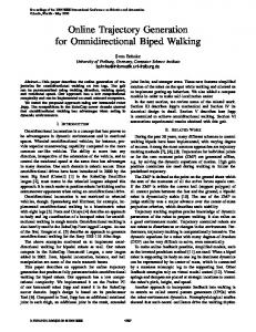
Fig. 2. Overview of an advanced PyMoCo application, utilizing the core PyMoCo objects and implementing custom trajectory generators with PyMoCo resources.
A more advanced, and realistic setup for sensor-based realtime trajectory generation, is illustrated in Fig. 2. It shows an application control at the application level which is strongly integrated with network communication systems, illustrated TM by connectors over ZeroC Ice (Henning (2004) [19]) and ROS; process control; sensor systems which naturally connect externally; and with a custom trajectory generator. The custom trajectory generator is developed using the PyMoCo software framework resources and takes on the real-time obligations toward the pertinent robot motion controller through the robot facade. 3.1: get_flange_pose
The most simple runtime setup using PyMoCo for robot control, illustrated by the UML object diagram in Fig. 1, uses an object of the ControllerManager class, included with PyMoCo. The ControllerManager class is managing the switch of trajectory generators at the request of the application code, ensuring that the switch will not skip a control cycle request from the motion control level. In the diagram in Fig. 1 weak or temporary associations are represented by dashed lines and more persistent object associations are illustrated by solid lines. The trajectory generator is exemplified by an object of the ToolLinearController class. It uses the core PyMoCo entities and provides its operational interface to a simple application; which is not specified by PyMoCo. The simple application, developed and provided by the user, thus only has to interface with the ControllerManager object and the trajectory generator objects that it requests from the controller manager. Fig. 1 also indicates a layered structure, where the native robot controller containing the motion controller is lowest, the PyMoCo run-time system is in the middle, and the application level at the top. In a simple setup as the one illustrated, PyMoCo may be considered more as a software service than a software framework, since the client system,
ros:ROSConnector
Application Level
: FrameComputer
4 3.1
4: compute_joint_step
: ToolLinearController
3.2: get_inverse_jacobian 3.2
2
5
1: moco_notify 2: get_joint_pos 1 6 5: set_joint_increment : RobotDefinition : RobotFacade 6: : serial2encoder
0: control_cycle_start
7
7: encoder_setpoint
0
: MotionController
Fig. 3. The real-time cycle illustrated as a UML collaboration diagram among core PyMoCo entities, the robot motion controller, and a trajectory generator (of the class ToolLinearController).
The detailed mechanisms of the control cycle involving the core elements of PyMoCo may be perceived from the UML collaboration diagram in Fig. 3. The focus here is on the computational real-time cycle from the trajectory generation level and down, and hence the application logic and control is not included. The MotionController class is not a real class, but included for representing the motion controller in the native robot controller. The trajectory generator used for illustration here is, again, of the class ToolLinearController. The control cycle is started by a notification from the motion controller to the robot facade in PyMoCo; typically
containing a lot of status information such as encoder readings, velocities, etc. The robot facade propagates the notification internally to a subscribing trajectory generator, which then, using PyMoCo run-time facilities, computes a control step in response. This control step is returned in serial joint kinematics coordinates to the robot facade, which translates it to encoder values and then in turn responds to the motion controller.
experiments are performed on one PC using local loop back networking, and thus do not measure the over-the-wire performance, the comparison is instructive. The purpose of the experiments presented in this section is different, in that it aims at making absolute, over-the-wire, realistic performance tests that are valid for PyMoCo-based trajectory generation applications.
C. Included Trajectory Generators
A. Experiment Setup
A (real-time) trajectory generator is an entity which ultimately carries the real-time responsibility of timely responding to the motion controller request for a new control-setpoint in joint space; or rather the joint encoder space. Neither the motion controller or the trajectory generators are core PyMoCo entities. PyMoCo includes a set of simple trajectory generators. They cover the typical trajectory generators that are represented by motion commands in the application platforms of standard industrial robot controllers. None of the included trajectory generators implement any advanced strategies for dealing with arm configuration singularities, joint speed or acceleration violations, joint limits, or other types of circumstances that may lead the motion control system to fail. Self-motion, or internal, singularities are dealt with by using a configurable singular value cutoff in the inverse Jacobian computation; which is probably the simplest possible strategy. The most common trajectory generators in standard robot controller are included: joint space linear motion, tool space linear motion, and real-time correction-responsive tool space linear motion. An additional two real-time responsive trajectory generators are included, which are rarely found in standard robot controllers, but immensely useful in real-time sensor-based robot control: tool space velocity motion and joint space velocity motion. The tool space velocity generator is the most frequently used in real-time sensor-based robot control applications at our laboratories.
The motion controller in the Universal Robots controller is interfaced at 125 Hz, i.e. a control period of 8 ms, and requires a response in 4 ms. In the real controller, the native application platform and trajectory generator can be shut down, and a custom “router” application started. This router application listens for external connections over TCP, and mediates contact with the motion controller internally in the robot controller. The router application, representing the motion controller, can be emulated on an ordinary PC, the purpose of which it is to log the response times from a PyMoCo application running off another PC and connecting through a switch. All hardware used is consumer grade and not of highest performance. Two PCs, both with an Intel i7 processor are used for performance measurements, connected through a standard 100 Mbit s−1 switch, and using the on-board Ethernet cards. The most important hardware to detail is the PC running the PyMoCo application. It is an Intel i7860 processor running at 2.80 GHz with four cores and two threads per core. Both PCs use the stock GNU/Debian Linux systems with Preempt-RT patched kernels of version 3.2.0-3-rt-686-pae; i.e. Real-Time Linux kernels. The most important software versions to mention are Python, 2.7.3rc2, and NumPy, 1.6.21. All software and kernels involved are taken from the official Debian testing repositories6 . Starting from a standard Debian desktop installation, a checklist of simple tweaks to ensure the best possible realtime performance was followed:
III. R EAL -T IME P ERFORMANCE The high flexibility and versatility of Python as an application platform for robot control, and as the implementation language of PyMoCo alike, come at the cost of computational performance and real-time quality. The real-time performance of a PyMoCo-based application is thus crucial to investigate. It is the outcome of such an investigation which will clarify whether PyMoCo is usable and feasible, and, if at all, for which applications and robots. This section presents results of an experimental setup based on the Universal Robots controller. The Universal Robots UR5 robot is used extensively in our laboratories, since it may be externally controlled and exhibits fairly low control delay and short motion response time; see Lind et al. (2010) [20]. Schrimpf et al. (2012) [21] compares three different setups for real-time trajectory generation; one of which is PyMoCo and the others based on OROCOS kinematics. Though their
1) Switch to single user mode. ($ telinit 1) 2) CPU frequency scaling should be set to “performance”. ($ cpufreq-set -c [0..7] -g performance) 3) Disable garbage collection in the Python code for the real-time critical computations. (gc.disable()/gc.enable()) 4) Put the control process in a real-time scheduler queue. ($ chrt 99 ...) 5) Run the RT-critical processes from a remote loginshell. ($ ssh ...) 6) Boot the Real-Time Linux kernel. All experiments were conducted at a length of 100 000 samples, which at 125 Hz amounts to about 13 min running time. 6 http://ftp.debian.org/debian/dists/testing/
B. Best Condition Performances The most important experiments were to measure the inherent response time of the PyMoCo run-time, by using the ZeroVelocityController, and to performance test the two most useful of the included trajectory generators: ToolVelocityController and ToolLinearController. All experiments were executed under the best obtainable real-time conditions, as per the check list in Section III-A.
Count [] Count []
Kinematics
Worst [s]
Average [s]
Std. dev. [s]
0.00174 0.00180
0.00149 0.00151
0.00006 0.00007
PyMoCo DH
Response times for 100k samples
Count []
joint transform functions. However, a DH formulation of the kinematics is also supported, reducing the number of matrix multiplications in the forward kinematics computation. The DH formulation was used in one run with the ToolVelocityController under the same conditions as the ones used in Table I. The comparable statistical results are seen in Table II
Zero Velocity Controller 4500 4000 3500 3000 2500 2000 1500 1000 5000 0.0006 0.0008 0.0010 0.0012 0.0014 0.0016 0.0018 0.0020 0.0022 0.0024
Tool Velocity Controller 10000 8000 6000 4000 2000 0 0.0006 0.0008 0.0010 0.0012 0.0014 0.0016 0.0018 0.0020 0.0022 0.0024 Tool Linear Controller 12000 10000 8000 6000 4000 2000 0 0.0006 0.0008 0.0010 0.0012 0.0014 0.0016 0.0018 0.0020 0.0022 0.0024 Respons time [s]
TABLE II M EASUREMENT OF KINEMATICS IN DH FORMULATION .
It turned out that the DH formulation, contrary to the expected, was slightly inferior to the standard formulation in PyMoCo. This can be traced to NumPy being relatively inefficient in assigning matrix element compared to multiplying matrices. D. System Tweak Performance Effects The last experiments addressed the effects of individual omission of the various real-time enhancement tweaks, shortlisted in Section III-A. Results are given in Table III. Tweak
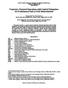
Fig. 4. Response time distribution for three different controllers. Average response time is marked by a vertical blue line and worst-case is marked by a vertical red line.
The results are visually observable from Fig. 4. Statistical summaries of the response time samples are shown in Table I. Trajectory Generator ZeroVelocityController ToolVelocityController ToolLinearController
Worst [s]
Average [s]
Std. dev. [s]
0.00144 0.00174 0.00236
0.00115 0.00149 0.00201
0.00010 0.00006 0.00008
TABLE I S TATISTICS OF MEASUREMENTS UNDER BEST REAL - TIME CONDITIONS .
These results show that the ToolLinearController is computationally much heavier than the ToolVelocityController; which was expected since it performs various checks along its path to control bounded acceleration ramp-up and rampdown of the velocity. More importantly, the results also show that both of the usable controllers are well within the 4 ms response time required by the Universal Robots motion controller. The inherent response time of PyMoCo indicated by the worst-case response time of the ZeroVelocityController gives the impression of the availability of control computation time for any useful trajectory generator. In case of a required 4 ms response time, there is of the order of 2.5 ms time available for any trajectory generator in each control cycle. C. DH-Kinematics Performance PyMoCo has a native kinematics formulation which is flexible for specifying separately static link transforms and
All tweaks - Single user - CPU freq. sched. - Disable GC - RT scheduling - RT kernel
Worst [s]
Average [s]
Std. dev. [s]
0.00174 0.00249 0.00265 0.00223 0.00203 0.00183
0.00149 0.00206 0.00212 0.00156 0.00155 0.00125
0.00006 0.00009 0.00007 0.00009 0.00005 0.00005
TABLE III E FFECT OF VARIOUS TWEAKS ON REAL - TIME PERFORMANCE .
It is observed from the table that all tweaks have significant effect on the worst-case performance. The lower average and higher worst-case response times of the standard kernel are natural, since the low-level real-time enhancements in the real-time kernel sacrifice some computational efficiency for gaining lower worst-case latency. The fact that the performance difference between a standard and a real-time kernel is so low is evidence of the flow of the real-time patches into the mainline Linux kernel over the recent years. IV. D ISCUSSION AND F URTHER W ORK This paper has presented an overview of the structure of PyMoCo, a flexible, Python-based software framework for trajectory generation and motion controller interfacing. Various real-time performance experiments for assessing its usability have been conveyed and the results have been presented and discussed. Under the presented experiment conditions, in terms of hardware, software, and system setup, it can be inferred that PyMoCo may be a usable software technology for trajectory generation in robot control applications where the over-the-wire response time limit is no lower than about some 3 ms.
The main contribution of PyMoCo is to provide users with a very flexible framework for building real-time sensor-based robot control applications at the laboratory prototyping stage. Many laboratory prototyping projects have already utilized PyMoCo, and it is considered good for learning and fast prototyping. However, being tied to the Python language and the Python run-time platform, it has no outlook of becoming industrially real-time reliable. The computational performance of contemporary CPUs together with the current implementation and design of PyMoCo is the limiting factor for its use in various setups. For instance, it is currently precluded that a KUKA LWR could be controlled by a PyMoCo-based application over FRI with maximum control rate. However, with CPU performance increasing over time, such setups may be achievable for PyMoCo in a not too distant future. Notwithstanding the automatic performance gains of future CPUs, there are a whole range of possibilities for increasing the inherent performance of a pure Python application. These range from downright porting of functional code to C/C++ extension modules, whereby some flexibility may be lost; over Cython (Behnel et al. (2011) [22]) for automated translation and compilation of computationally critical code blocks; with PyPy, a very fast re-implementation of the Python run-time; to simply using more optimal and specialized technologies within PyMoCo, e.g. integrating PyKDL for kinematics computations as demonstrated by Schrimpf et al. (2012) [21]. Among useful and functional features that will be addressed in the future work with PyMoCo are facilities for trajectory blending. The methods described by Lloyd and Hayward (1993) [23] and Volpe (1993) [24] are under consideration. R EFERENCES [1] J. D. Schutter, T. D. Laet, J. Rutgeerts, W. Decré, R. Smits, E. Aertbeliën, K. Claes, and H. Bruyninckx, “Constraint-based task specification and estimation for sensor-based robot systems in the presence of geometric uncertainty,” International Journal of Robotics Research, vol. 26, no. 5, pp. 433–455, May 2007. [2] W. Decré, “Optimization-Based Robot Programming with Application to Human-Robot Interaction,” Ph.D. dissertation, Katholieke Universiteit Leuven, 2011. [3] Euron, “Sectorial Report on Industrial Robot Automation,” European Robotics Network, Tech. Rep., July 2005, http://www.euron.org/ miscdocs/docs/euron2/year2/dr-14-1-industry.pdf. [4] D. Dallefrate, D. Colombo, and L. M. Tosatti, “Development of robot controllers based on PC hardware and open source software,” in Seventh Real-Time Linux Workshop, Nov. 2005. [Online]. Available: http://www.realtimelinuxfoundation.org/events/rtlws-2005/ws.html [5] D. Kubus, A. Sommerkorn, T. Kröger, J. Maaß, and F. M. Wahl, “Low-level control of robot manipulators: Distributed open real-time control architectures for stäubli rx and tx manipulators,” in ICRA 2010 Workshop on Innovative Robot Control Architectures for Demanding (Research) Applications, D. Kubus, K. Nilsson, and R. Johansson, Eds. Technical University of Braunschweig, 2010, pp. 38–45. [Online]. Available: http://www.rob.cs.tu-bs.de/en/news/icra2010 [6] K. Buys, S. Bellens, W. Decre, R. Smits, E. Scioni, T. D. Laet, J. D. Schutter, and H. Bruyninckx, “Haptic coupling with augmented feedback between two KUKA Light-Weight Robots and the PR2 robot arms,” in International Conference on Intelligent Robots and Systems. IEEE/RSJ, Sept. 2011, pp. 3031–3038.
[7] G. Schreiber, A. Stemmer, and R. Bischoff, “The Fast Research Interface for the KUKA Lightweight Robot,” in ICRA 2010 Workshop on Innovative Robot Control Architectures for Demanding (Research) Applications, D. Kubus, K. Nilsson, and R. Johansson, Eds. Technical University of Braunschweig, 2010, pp. 15–21. [Online]. Available: http://www.rob.cs.tu-bs.de/en/news/icra2010 [8] H. Bruyninckx, “Open Robot Control Software: the OROCOS project,” in International Conference on Robotics and Automation, vol. 3. IEEE, 2001, pp. 2523–2528. [9] H. Bruyninckx, P. Soetens, and B. Koninckx, “The Real-Time Motion Control Core of The Orocos Project,” in International Conference on Robotics and Automation, vol. 2. IEEE, Sept. 2003, pp. 2766–2771. [10] M. Quigley, K. Conley, B. P. Gerkey, J. Faust, T. Foote, J. Leibs, R. Wheeler, and A. Y. Ng, “ROS: an open-source Robot Operating System,” in ICRA Workshop on Open Source Software, 2009. [Online]. Available: http://www.willowgarage.com/sites/default/files/ icraoss09-ROS.pdf [11] T. Kröger and F. M. Wahl, “Low-level control of robot manipulators: A brief survey on sensor-guided control and on-line trajectory generation,” in ICRA 2010 Workshop on Innovative Robot Control Architectures for Demanding (Research) Applications, D. Kubus, K. Nilsson, and R. Johansson, Eds. Technical University of Braunschweig, 2010, pp. 46–53. [Online]. Available: http://www.rob. cs.tu-bs.de/en/news/icra2010 [12] G. v. Rossum, “Glue It All Together With Python,” in Workshop on Compositional Software Architectures, C. Thompson, Ed. Object Services and Consulting, Inc., Feb. 1998. [Online]. Available: http://www.objs.com/workshops/ws9801/papers/paper070.html [13] X. Cai, H. P. Langtangen, and H. Moe, “On the performance of the Python programming language for serial and parallel scientific computations,” Scientific Programming, vol. 13, no. 1, pp. 31– 56, 2005. [Online]. Available: http://iospress.metapress.com/content/ xawr0dx9xg61nb7q/ [14] J. Schrimpf, L. E. Wetterwald, and M. Lind, “Real-Time System Integration in a Multi-Robot Sewing Cell,” in International Conference on Intelligent Robots and Systems. IEEE/RJS, Aug. 2012, accepted. [15] M. Lind, “Automatic Robot Joint Offset Calibration,” in International Workshop of Advanced Manufacturing and Automation, K. Wang, O. Strandhagen, R. Bjartnes, and D. Tu, Eds. Trondheim, Norway: Tapir Academic Press, June 2012. [16] L. Tingelstad, A. Capellan, T. Thomessen, and T. K. Lien, “MultiRobot Assembly of High-Performance Aerospace Components,” in IFAC Symposium on Robot Control, 2012, accepted. [17] J. Schrimpf, M. Lind, and G. Mathisen, “Time-Analysis of a RealTime Sensor-Servoing System using Line-of-Sight Path Tracking,” in International Conference on Intelligent Robots and Systems. IEEE/RJS, Sept. 2011, pp. 2861–2866. [18] M. Lind and A. Skavhaug, “Using the blender game engine for real-time emulation of production devices,” International Journal of Production Research, vol. 0, no. 0, pp. 1–17, 2011, online available, iFirst. [19] M. Henning, “A New Approach To Object-Oriented Middleware,” IEEE Internet Computing, vol. 8, no. 1, pp. 66–75, Aug. 2004. [20] M. Lind, J. Schrimpf, and T. Ulleberg, “Open Real-Time Robot Controller Framework,” in CIRP Conference on Assembly Technologies and Systems, T. K. Lien, Ed. NO-7005, Trondheim, Norway: Tapir Academic Press, June 2010, pp. 13–18. [21] J. Schrimpf, M. Lind, A. Skavhaug, and G. Mathisen, “Implementation Details of External Trajectory Generation for Industrial Robots,” in International Workshop of Advanced Manufacturing and Automation, K. Wang, O. Strandhagen, R. Bjartnes, and D. Tu, Eds. Trondheim, Norway: Tapir Academic Press, June 2012. [22] S. Behnel, R. Bradshaw, C. Citro, L. Dalcin, D. S. Seljebotn, and K. Smith, “Cython: The Best of Both Worlds,” Computing in Science Engineering, vol. 13, no. 2, pp. 31 –39, Apr. 2011. [23] J. Lloyd and V. Hayward, “Trajectory generation for sensor-driven and time-varying tasks,” International Journal of Robotics Research, vol. 12, no. 4, p. 380, Aug. 1993. [24] R. Volpe, “Task space velocity blending for real-time trajectory generation,” in International Conference on Robotics and Automation, vol. 2. IEEE, May 1993, pp. 680–687.