Reasoning about the Behavior of Semantic Web Services with Concurrent Transaction Logic Dumitru Roman
Michael Kifer
University of Innsbruck, DERI Innsbruck, Austria
State University of New York at Stony Brook, USA
[email protected]
[email protected]
ABSTRACT The recent upsurge in the interest in Semantic Web services and the high-profile projects such as the WSMO, OWLS, and SWSL, have drawn attention to the importance of logic-based modeling of the behavior of Web services. In the context of Semantic Web services, the logic-based approach has many applications, including service discovery, service choreography, enactment, and contracting for services. In this paper we propose logic-based methods for reasoning about service behavior, including the aforementioned choreography, contracting, and enactment. The formalism underlying our framework is Concurrent Transaction Logic—a logic for declarative specification, analysis, and execution of database transactions. The new results include reasoning about service behavior under more general sets of constraints and extension of the framework towards conditional control and data flow—two crucial aspect that were missing in previous logical formalizations.
1.
INTRODUCTION
The idea and the promise of combining the Semantic Web with Web services has attracted intense interest in the research community and industry. The early projects like OWL-S1 and SWSL2 were followed by bigger and more sustained efforts like WSMO,3 which is at the center of a series of large European integrated projects, such as DIP4 and SUPER.5 The research problems in this area are many and varied in nature: ontology specification languages that must go well beyond OWL, service discovery, service choreography (i.e., specification of how autonomous client agents interact with services), automated contracting for services, service enactment, execution monitoring, and others. In this paper 1
http://www.daml.org/services/owl-s/ http://www.w3.org/Submission/SWSF-SWSL/ 3 http://www.wsmo.org/ 4 http://dip.semanticweb.org/ 5 http://ip-super.org/ 2
Permission to copy without fee all or part of this material is granted provided that the copies are not made or distributed for direct commercial advantage, the VLDB copyright notice and the title of the publication and its date appear, and notice is given that copying is by permission of the Very Large Data Base Endowment. To copy otherwise, or to republish, to post on servers or to redistribute to lists, requires a fee and/or special permission from the publisher, ACM. VLDB ’07 Vienna, Austria Copyright 2007 VLDB Endowment, ACM 978-1-59593-649-3/07/09.
627
we address a subset of the aforesaid problems: modeling, contracting, and enactment. Our approach is based on Concurrent Transaction Logic (CTR) [6]. It continues the earlier line of research described in [7, 16, 8]. The use of CTR for process modeling in workflows was first advocated in [7], where a scheduling algorithm for executing workflows under temporal and causality constraints was introduced. The present work extends those results fivefold. First, we allow a significantly more complex set of constraints, which encompasses all the constraints available in the recently proposed language DecSerFlow [19]. Second, data flow, without which any description of a service of workflow is unrealistic, is now part of the framework. Third, the framework now includes conditional process controls. Fourth, the algorithms are greatly improved by expanding the proof theory of CTR, which allowed us to replace various ad hoc parts of the earlier approaches (such as the so-called knot elimination in [7, 8]). Finally, we show how our framework applies to service choreography and contracting—areas whose logical foundations have not seen much research. In [8], CTR was extended to a logic, called CTR-S, which was designed for modeling service choreography and contracting. However, CTR-S turned out to be a very complex formalism and the results were limited to rather simple forms of contracting. The present paper uses a much simpler logic, CTR, but complex patterns of choreography and contracting can be modeled nonetheless. Our new techniques significantly extend the kinds of service contracts that can be handled, but it is not known whether and how much is given up in terms of choreography. Finally, [16] introduced techniques from constraint logic programming to the problem of service enactment under aggregate constraints (such as aggregate cost of service execution). We incorporate some of those techniques to model the data flow that arises in service choreography and contracting. Further discussion of related work appears in Section 7. The remainder of this paper is organized as follows. Section 2 describes the basic techniques from process modeling, which includes control flow, data flow, and constraints. It then outlines our framework in which service choreography and the process of contracting for services can be handled using these techniques. To make the paper self-contained, Section 3 gives a short introduction to CTR. Section 4 shows how the framework outlined in Section 2 is formalized in CTR. Section 5 describes the verification procedure, which is the key component of service contracting in our framework. Section 6 puts the various parts of our framework together and summarizes
the entire approach. Section 7 presents related work, and Section 8 concludes this paper.
2.
SERVICE BEHAVIOR: MODELING, REASONING, AND ENACTMENT
cards or cheques and in some cases the service might require those payments to be secured by a credit card (if the available limit exceeds the price) or by providing a guarantor of payment. Under certain circumstances, the client may get a rebate. The figure represents the pattern of interaction with the service using so-called control flow graph.
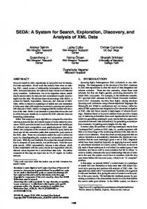
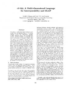
Figure 1 depicts the main aspects of service behavior addressed in our work. The behavior of the service is described through its choreography—a specification of how to invoke and interact with the service in order to get results. This is known as the WSMO model of choreography.6 The W3 Choreography group’s model includes both the service interactions and the client interactions.7 This model is symmetric and can be represented in our framework by including the choreography, policy, and contract components on both the client and the service side in the figure. This can be further extended to multiagent interactions. However, these issues are beyond the scope of this paper and are orthogonal to the reasoning problems, which we consider here. One way to describe the choreography interface of the service is through the control and data flow graphs. Figure 2: A control-flow graph.
Figure 1: Elements of the reasoning architecture for semantic Web services. The service policy component in Figure 1 is a set of additional constraints imposed on the choreography and on the input. The contract requirements included on the client side of the figure, represents the contractual requirements of the user, which go beyond the basic functions (such as selling books or helping with travel arrangements) of the service. Thus, in our framework, the choreography of a service is described with control and data flow graphs, while service policy and clients’ contract requirements are described with constraints. We will now discuss these modeling tools in more detail using a concrete scenario depicted in Figure 2. Control flow graphs. Figure 2 depicts a fairly complex pattern of interaction with a service that sells high ticket items. It includes provisions for optionally giving rebates to customers who fulfill certain requirements as well as a possibility that customers might return the ordered items and receive partial refund. Payment is allowed by credit 6 7
http://www.wsmo.org/TR/d14/ http://www.w3.org/TR/2006/WD-ws-cdl-10-primer-20060619/
628
A control flow graph is typically used to specify local execution dependencies among the interactions with the service; it is a good way to visualize the overall flow of control. Such a graph has an initial and the final interaction, the successor-interaction for each interaction in the graph, and whether these successors must all be executed concurrently or in some unspecified order (represented using AND-split nodes), or whether only one of the alternative branches needs to be executed non-deterministically (represented using OR-nodes). In Figure 2, all successors of the initial interaction place order must be executed, but all these successors are OR-split nodes. For example, the lowermost successor node of place order is an OR-node and only one of its successors, pay chq or pay CC, is supposed to be executed. The node delivery is also an OR-split, but with a twist. The upper branch going out of this node represent a situation where a customer accepts delivery but then returns the purchased item. The lower branch, however, has no interactions, and it joins the upper branch. This means that the upper branch is optional : the customer may or may not return the item. Similarly, the rightmost segment of the graph indicates that rebate is an optional interaction. We note two more things about the graph in Figure 2: the shaded boxes labeled with security and pay, and the condition credit limit > price attached to the arc leaving the node give CC. These boxes delineate control flow subgraphs corresponding to complex interactions that are composed of several sub-interactions (such as providing security). If a control graph represents a workflow then these complex interactions are called subworkflows. The aforesaid condition credit limit > price is called a transition condition. It says that in order for the next interaction with the service to take place the condition must be satisfied. The parameters credit limit and price may be obtained by querying the current state of the service or they may be passed as parameters from one interaction to another—the actual method depends on a concrete representation. In general, transition conditions are Boolean expressions attached to the arcs in control flow graphs. Only the arcs whose conditions are true can be followed at run time. In general, a
control flow graph may contain additional elements, such as loops. However, our main results apply only to cases when constraints and loops do not interact. For simplicity, in Section 4.2 we assume that our control flow graphs are acyclic. Constraints. Control flow graphs are typically used to represent local dependencies among interactions in a choreography interface. Global dependencies often arise as part of policy specification; they take the form of global temporal and causality constraints. Yet another situation when global constraints arise is when a client has specific requirements to interaction with the service. These requirements have little to do with the functionality of the service (e.g., selling books), but rather with the particular guarantees that the client wants before entering into a contract with the service. We call such sets of client-side constrains client contract requirements. Figure 3 gives an example of global constraints that represent service policy and client contract requirements for our running example. Service policy 1. If pay CC (paying by credit card) takes place after accepting delivery then giving security must precede delivery 2. If pay chq takes place after accepting delivery then pay chq (paying by cheque) immediately follows delivery 3. If rebate is given then pay must precede accepting delivery
Client contract requirements 4. The interaction of accepting delivery must precede pay chq
Figure 3: Global behavioral constraints. Data flow graphs. Any series of interactions with a service typically involves passing data, and the flow of data among these interactions is normally modeled using graphs. A data flow graph is like a control flow graph except that the arcs represent the routes along which data is passed from one interaction to the other. These arcs are labeled with data items that are being passed around. Since, in many cases, control flow is accompanied by passing data, a data flow graph often has many arcs inherited from the control flow graph. However, the nodes in a data flow graph do not need to be labeled as AND- or OR-splits. A data flow graph for our running example is depicted in Figure 4.
those arcs. In fact, this item (and some others) are passed along almost all arcs in the graph and to avoid cluttering the picture we did not include them. One important observation is that the interactions at the ends of the arcs in the data flow graph must be ordered in time, since generally the interaction that receives an item must wait for the interaction that produces the item. However, this interaction is not only temporal but also conditional. For instance, the interaction partial refund receives the credit card number from give CC only if the client gives a credit card. Such features must be representable in the underlying formalism. Service enactment. Service enactment deals with the execution of the process underlying the service. Interactions in the choreography interface must be first scheduled (i.e. ordered) according to the model specified by the control and data flow graphs, the service policy, etc., and then executed. Process scheduling is a non-trivial problem and solutions have typically high computational complexity [13]. Existing approaches to process scheduling can be classified as passive and proactive. Passive schedulers receive sequences of events from an external source, such as a process or a transaction manager, and verify that these sequences satisfy all global constraints (possibly after reordering some events in the incoming sequences). Several such schedulers are described in [17, 2, 12]. In passive scheduling, an unspecified external system is supposed to ensure that scheduling complies with all the constraints, that liveness of the scheduling strategy is observed. The known algorithms for these tasks are worst-case exponential and constraints are enforced at run time. Proactive scheduling does not rely on external systems. Instead, it constructs a concise (as much as possible) explicit representation of all allowed executions (executions that satisfy all constraints)—either in advance or dynamically. The representation of all valid schedules is then used by the scheduler. Depending on the expressiveness of the framework, such scheduling can be linear at run time, since there is no need to verify constraints after the construction stage. In a sense, all constraints get compiled into the aforesaid concise representation. One such proactive approach is described in [7]. Although [7] proposes a linear run-time scheduler this is achieved by placing limits on process modeling, which does not permit transition conditions in control flow graphs and does not consider data flow.
3. THE BASICS OF CTR
Figure 4: A data-flow graph. The parts inherited from the control flow graph are shaded to help focus attention on the new elements. The data flow graph has two new arcs, which represent non-local passing of the credit card information. Also, the arcs going out of the initial interaction place order are labeled with the Order# item to indicate that this item is being passed along
629
The formalism used in this paper to model, reason, and enact service choreographies is Concurrent Transaction Logic or CTR [6]. This section is a short summary of the relevant parts of CTR’s syntax and an informal explanation of its semantics. Due to space limitation, we cannot expand on these issues, but details can be found in [6]. CTR is a conservative extension of the classical predicate logic in the sense that both its proof theory and the model theory reduce to classical logic for formulas that do not cause state transitions (but only query the current state). Basic syntax. The atomic formulas of CTR are identical to those of the classical logic, i.e., they are expressions of the form p(t1 , . . . , tn ), where p is a predicate symbol and the ti ’s are function terms. More complex formulas are built
with the help of connectives and quantifiers. Apart from the classical ∨, ∧, ¬, ∀, and ∃, CTR has two additional connectives, ⊗ (serial conjunction) and | (concurrent conjunction), and a modal operator ¯ (isolated execution). For instance, ¯(p(X) ⊗ q(X)) | (∀Y (r(Y ) ∨ s(X, Y ))) is a well-formed formula. Informal semantics. Underlying the logic and its semantics is a set of database states and a collection of paths. For the purpose of this paper, the reader can think of the states as just a set of relational databases, but the logic does not rely on the exact nature of the states—it can deal with a wide variety of them. A path is a finite sequence of states. For instance, if s1 , s2 , ..., sn are database states, then hs1 i, hs1 , s2 i, and hs1 , s2 , ..., sn i are paths of length 1, 2, and n, respectively. Just as in classical logic, CTR formulas assume truth values. However, unlike classical logic, the truth of CTR formulas is determined over paths, not at states. If a formula, φ, is true over a path hs1 , ..., sn i, it means that φ can execute starting at state s1 . During the execution, the current state will change to s2 , s3 , ..., etc., and the execution terminates at state sn . With this in mind, the intended meaning of the CTR connectives can be summarized as follows: • φ ⊗ ψ means: execute φ then execute ψ. Or, modeltheoretically, φ ⊗ ψ is true over a path hs1 , ..., sn i if φ is true over a prefix of that path, say hs1 , ..., si i, and ψ is true over the suffix hsi , ..., sn i. • φ | ψ means: φ and ψ must both execute concurrently, in an interleaved fashion. • φ ∧ ψ means: φ and ψ must both execute along the same path. In practical terms, this is best understood in terms of constraints on the execution. For instance, φ can be thought of as a transaction and ψ as a constraint on the execution of φ. It is this feature of the logic that lets us specify constraints as part of process specifications. • φ∨ψ means: execute φ or execute ψ non-deterministically. • ¬φ means: execute in any way, provided that this will not be a valid execution of φ. Negation is an important ingredient in temporal constraint specifications. • ¯φ means: execute φ in isolation, i.e., without interleaving with other concurrently running activities. This operator enables us to specify the transactional parts of process specifications. q Concurrent-Horn subset of CTR. Implication p is defined as p ∨ ¬q. The form and the purpose of the implication in CTR is similar to that of Datalog: p can be thought of as the name of a procedure and q as the definition of that procedure. However, unlike Datalog, both p and q assume truth values on execution paths, not at states. More precisely, p q means: if q can execute along a path hs1 , ..., sn i, then so can p. If p is viewed as a subroutine name, then the meaning can be re-phrased as: one way to execute p is to execute its definition, q. The control flow parts of service choreographies are formally represented using concurrent-Horn goals and concurrent Horn rules. A concurrent Horn goal is: • any atomic formula is a concurrent-Horn goal;
←
←
630
• φ ⊗ ψ, φ | ψ, and φ ∨ ψ are concurrent-Horn goals, if so are φ and ψ; • ¯φ is a concurrent-Horn goals, if so is φ. A concurrent-Horn rule is a CTR formula of the form body, where head is an atomic formula and body head is a concurrent-Horn goal. Observe that the definition of concurrent-Horn rules and goals does not include the connective ∧. In general, ∧ represents constrained execution, which is usually hard to implement, since constraints must be checked at every step of the execution. If a constraint violation is detected, a new execution path must be tried out. In contrast, the concurrentHorn fragment of CTR is efficiently implementable, and there is an SLD-style proof procedure that proves concurrentHorn formulas and executes them at the same time [6]. The efficiency gap between concurrent-Horn execution and constrained execution is the main motivation for our results. In a previous work by one of the authors [7], it was shown that for a certain class of constraints, formulas of the form ConcurrentHornGoal ∧ Constraints, have an equivalent concurrent-Horn representation (which, therefore, does not use the connective ∧). This enabled the use of the proof theory for Horn CTR as a means of obtaining a linear run-time scheduling algorithm (as opposed to, for example, exponential run-time scheduling in [18, 19]). In the present work, we consider a larges class of constraints than in [7], and this precludes the strategy used in [7]. We can still borrow some of the ideas from that early work and transform ConcurrentHornGoal ∧ Constraints into a conjunction that uses a smaller set of special kind of constraints. Although this conjunction cannot be further reduced to a concurrent Horn goal, we extend the proof theory of CTR to obtain a gain similar to [7]. Furthermore, we eliminate the need for having to compile away certain precedence constraints, which in [7] were handled in an expensive way. Instead, these constraints are now handled by an extended proof theory.
←
Elementary updates. We complete our informal introduction to CTR by explaining how execution of (some) formulas may actually change the underlying database state. Most of the machinery has already been introduced (albeit very informally). What is missing is the notion of elementary updates. In CTR, elementary updates are represented by ordinary atomic, variable-free formulas. Syntactically, CTR does not distinguish elementary updates in any way, but the user may want to do so by adopting a syntactic convention (e.g., a convention could be that insert.p(t) represents the act of insertion of tuple t into the relation p). What distinguishes elementary updates is their semantics. Through some black magic, called transition oracle, CTR arranges that each elementary updates is always true along certain arcs, i.e., paths of the form hs1 , s2 i. Informally, one can think of an elementary update as a binary relation over states. For instance, if hs1 , s2 i belongs to the relation corresponding to an elementary update u, it means that u can cause a transition from state s1 to state s2 . Note that an update can be non-deterministic (any one of a number of alternative state transitions might be possible) and it is possible for an update to be inapplicable in certain states (for instance, delete.p(t) may be applicable only if p(t) is true in the current state).
This mechanism is very general. It accounts for a wide variety of elementary state changes: from simple tuple insertions and deletions, to relational assignments, to updates performed by legacy programs, to whatever workflow activities might do. The connectives of CTR are then used to build more complex updates from the elementary ones and then to combine these complex updates into even more complex update programs. This process of building CTR programs from the ground up is very natural and powerful. The reader is referred to [3, 5, 6] for concrete examples.
4.
MODELLING SERVICES WITH CTR
We now use CTR to represent the control flow, constraints, and the data flow aspects of service choreographies.
4.1
Control Flow
In [7], it was shown that concurrent Horn goals are natural formalizations of so called structured control flow graphs. Nodes in such graphs can be represented by atomic formulas with parameters that are used for representing data flow. When concrete values are substituted for the parameters, these formulas act as elementary state transitions of CTR (see the end of the previous section). The connective ⊗ represents sequential composition of interactions and is reflected by the arcs connecting adjacent nodes. The connective | is used to specify interactions that can be done in parallel; it is represented by the AND-split nodes in the graph. Classical disjunction ∨ represents non-deterministic choice and corresponds to the OR-split nodes in the graphs. Transition conditions between adjacent nodes are modeled as queries that are sequentially composed with the formulas that label the nodes in question. Subworkflows (or complex interactions in service choreography—see Section 2) are modeled with rules. The head of such a rule represents the subworkflow’s name (the name of a shaded box in Figure 2) and the body represents the subgraph corresponding to the subworkflow. In this paper we model not only control flow but also data flow, so the nodes in the control graph are no longer propositions, but predicates with variables. These variables is one mechanism for specifying the data flow. Other data exchanges may happen through the database state. In this case, the producer inserts a data item into the shared database state, and the consuming interaction retrieves it. To illustrate, we use CTR to represent the flow of control and data for our running example (cf. Figures 2 and 4). The CTR representation (1) uses a special proposition, path, to indicate optional actions. It is defined as φ ∨ ¬φ, for some (does not matter which) formula φ. This means that path is true on all possible execution paths. It is a counterpart of the proposition “true” in classical logic. The proposition path will also be used to represent temporal constraints in our framework. One can see that in (1) rules are used to represent subworkflows and variables (such as Order#) to pass data among choreography interactions. Other instances of data flow, such as passing the credit card number from give CC to partial refund is done through the underlying state: the credit card number is inserted into the state by give CC and queried by partial refund.
4.2
Events and Constraints
631
place order(Order#, P rice) ← ( ( delivery(Order#) ⊗ (ref und(Order#) ∨ path) ) | ( security(Order#, P rice) ∨ path ) | pay(Order#, P rice) ) ⊗ (rebate(Order#) ∨ path) ⊗ end security(Order#, P rice) ← give guarantor(Order#) ∨ ( give CC(Order#, CC#)⊗ credit limit(CC#, Limit) ⊗ Limit > P rice ) pay(Order#, P rice) ← pay chq(Order#, P rice) ∨ pay CC(Order#, P rice) ref und(Order#) ← return(Order#) ⊗ partial ref und(Order#) partial ref und(Order#) ← ( payment(Order#, cc, CC#)⊗ ref und amount(Order#, Amount)⊗ issue credit CC(CC#, Amount) ) ∨ ( payment(Order#, cheque, Cheque#)⊗ ref und amount(Order#, Amount)⊗ send check(Order#, Amount) ) give CC(Order#, CC#) ← insert.payment(Order#, cc, CC#) pay chq(Order#, P rice) ← get cheque(P rice, Cheque#)⊗ insert.payment(Order#, cheque, Cheque#) pay CC(Order#, P rice) ← payment(Order#, cc, CC#) ⊗ charge(CC#, P rice)
(1)
In process-oriented information systems, tasks are typically modeled in terms of their externally observable events, such as start, commit, precommit, abort, terminated, etc. Such events can be directly incorporated as nodes in a control flow graph. (For brevity, our running example collapses all significant events for the same task into one event.) Temporal and causality constraints among nodes of the graph are then expressed in terms of these events. For simplicity, we restrict choreographies to be non-iterative, which means that we do not use recursive CTR rules. This generalizes easily to iterative processes and recursive rules as long as the constraints do not involve the events that occur inside the loops. Definition 4.1 (Assumptions). We make the following assumptions, which simplify the discussion, but do not limit the generality of the approach. • No significant event occurs twice during the execution. • Each significant event is represented as an elementary update that applies in every state. The first assumption does not limit generality, since we are dealing with non-iterative processes and can always rename different occurrences of the same type of event. The second assumption means that we require each significant event to leave a footprint in the underlying database state. This is commonly done by maintaining a system log where footprints are recorded. 2 The first assumption above translates into the following unique event property. Definition 4.2 (Unique Event Property). A concurrentHorn goal G has the unique event property if and only if every significant event occurs at most once in every execution of G. In such cases, we shall also say that G is a uniqueevent goal. 2 Unique-event goals can be recognized in linear time in the size of the goal. It is easy to see that the unique event property implies the following:
• If G = E1 ⊗ E2 is a unique-event goal and α occurs in E1 then it cannot occur in E2 . • If G = E1 | E2 is a unique-event goal and α occurs in E1 then it cannot occur in E2 . • If G = E1 ∨ E2 then G is a unique-event goal if and only if so are both E1 and E2 . In the rest of this paper, all concurrent-Horn goals are assumed to have the unique event property. Transaction Logic can express a wide variety of temporal constraints [4], but in this paper we are looking for sets of constraints that are general enough to be used for service policies and client contracts and yet the computational complexity of reasoning about such constraints must be better than what follows from known results. In [7] we studied reasoning about set of constraints, which subsume Singh’s Event Algebra [18]. In this paper, we extend this set to cover all constraints of the DecSerFlow language [19]. Using these constraints we can specify that one task must start before some other task, that some task must start right after another one has finished, that execution of one task causes some other task to be executed or not executed, etc. The DecSerFlow constraints [19] are believed to be sufficient for the needs of process-aware information systems. We specify all significant events in the system as formulas drawn from a set denoted by E VEN T . Unlike [7], we use predicates with variables— not just propositions—to represent control and data flow. In [7], the events could be simple propositions, but in our case they are existentially quantified atomic formulas of the form ∃DataF lowV ars eventN ame(DataF lowV ars) Here eventName is the event (or interaction) that is supposed to happen (or not happen), and DataFlowVars are the data flow parameters used in modeling this event (see (3), for example). Definition 4.3 (Constraints). The basic building blocks of C ON ST R are formulas of the form path ⊗ e ⊗ path, path ⊗ e, and e ⊗ path, where e ∈ E VEN T . Then the following constraints form the constraint algebra C ON ST R: 1. Primitive constraints: If e ∈ E VEN T then path⊗e⊗ path (event e must happen) and ¬(path ⊗ e ⊗ path) (event e must not happen) are primitive constraints in C ON ST R. For convenience we use a shorthand notation Oe for path ⊗ e ⊗ path. Then we say that Oe is a positive primitive constraint and ¬Oe is a negative primitive constraint. 2. Immediate serial constraints: If e1 , ..., en ∈ E VEN T , then path ⊗ ¯(e1 ⊗ · · · ⊗ en ) ⊗ path (events e1 , ..., en must happen next to each other with no other events in-between) is a (positive) immediate serial constraint in C ON ST R. We use the shorthand O ¯ (e1 ⊗ · · · ⊗ en ) to represent path ⊗ e1 ⊗ · · · ⊗ en ⊗ path. This type of constraints is quite hard to enforce, and it was not allowed in [7]. We will see an interesting use for such constraints in our running example. 3. Serial constraints: If s1 , ..., sn ∈ C ON ST R are positive primitive constraints or positive immediate serial constraints, then s1 ⊗ · · · ⊗ sn ∈ C ON ST R is a serial constraint. We will also sometimes call constraints of
632
the form Oa ⊗ Ob plain serial constraints (as opposed to the immediate ones). 4. Complex constraints: If C1 , C2 ∈ C ON ST R then so are C1 ∧ C2 , and C1 ∨ C2 . Nothing else is in C ON ST R.
2
To get a better picture of what can be expressed using C ON ST R, we show some examples. • Oe ∧ Of — events e and f must both occur (in any order). • ¬Oe∨¬Of — it is not possible for e and f to happen together. • ¬Oe ∨ Of — if event e occurs, then f must also occur (before or after e). This can be more naturally represented using implication: Oe → Of . • ¬Oe ∨ (Oe ⊗ Of ) — if event e occurs, then f must occur later. Equivalently: Oe → (Oe ⊗ Of ). • ¬Of ∨ (Oe ⊗ Of ) — if event f has occurred, then event e must have occurred some time prior to that. • ¬Oe ∨ ¬Of ∨ (Oe ⊗ Of ) — if both e and f occur, then e must come before f . Equivalently: (Oe ∧ Of ) → (Oe ⊗ Of ). • ¬Oe ∨ O ¯ (e ⊗ f ) — if event e occurs, then f must occur right after e with no event in-between. • ¬Ok ∨ ¬Od ∨ O ¯ (k ⊗ d) — if k and d both occur then d must happen right after k with no other event in-between. Equivalently: (Ok ∧ Od) → O ¯ (k ⊗ d)
It was also shown in [7] that the constraints in C ON ST R (without the immediate serial constraints) can be converted to the following normal form: ∨i (∧j serialConstri,j )
(2)
where each serialConstri,j is either a primitive constraint or a serial constraint composed of two positive primitive constraints. This result generalizes to the constraints of the form O ¯ (...) quite easily, because any immediate serial constraint of the form O ¯ (a ⊗ b ⊗ c) is equivalent to O ¯ (a ⊗ b) ∧ O ¯ (b ⊗ c). Therefore, any immediate serial constraint can be replaced with a conjunction of binary immediate constraints. Although Definition 4.3 does not say that C ON ST R is closed under negation, it was shown in [7] that (without the immediate serial constraints) it is. This makes it possible to express some constraints easier than otherwise. For instance: • ¬(Oe ⊗ Of ) — it is not possible for f to occur after e (and for e before f ). Without direct negation of a serial constraint, this would be much more complex: ¬Oe ∨ ¬Of ∨ (Of ⊗ Oe). • ¬(Oe ⊗ Of ⊗ Og) — if e happens and then f , then g cannot come later.
The result of [7] that C ON ST R is closed under negation can be extended to include constraints of the form O ¯ (...), but this requires a new construct: existential events, denoted O?i , for i = 1, ..., n, .... A constraint of the form O?i ⊗ Ob means that some event from E VEN T must occur before b. A constraint (O?i ⊗ Ob) ∧ (Oa ⊗ O?i ) means that some event must occur before b and the same event must occur after a. That is, it must occur in-between a and b. By the unique event property, this event must be different from both a and b and, therefore, a cannot be immediately followed by b. We will now extend E VEN T with symbols ?1 , ?2 , ..., where each ?i represents some concrete, but unknown event from E VEN T . With this in mind, we can see that negation of any binary immediate serial constraint O ¯ (a ⊗ b) is equivalent to a constraint where negation is applied only to primitive events: ¬Oa ∨ ¬Ob ∨ (Oa ⊗ O?i ) ∨ (O?i ⊗ Ob), for some ?i
that does not occur elsewhere in C ON ST R. Since general immediate serial constraints can be split into binary ones, it shows that C ON ST R is closed under application of negation to immediate constraints. We can now show that C ON ST R is sufficiently expressive to formalize the policy and contract constraints for our running example (see Figure 3). For readability, we use implication instead of the disjunctive form (2): 1. ¡∃ Order# ∃ P rice (Odelivery(Order#) ⊗ Opay CC(Order#, P rice)) → ¢ (Osecurity(Order#, P rice) ⊗ Odelivery(Order#)) 2. ¡∃ Order# ∃ P rice (Odelivery(Order#) ⊗ Opay chq(Order#, P rice)) → ¢ O ¯ (delivery(Order#) ⊗ pay chq(Order#, P rice)) 3. ¡∃ Order# ∃ P rice Orebate(Order#) → ¢ (Opay(Order#, P rice) ⊗ Odelivery(Order#)) 4. ¡∃ Order# ∃ P rice ¢ Odelivery(Order#) ⊗ Opay chq(Order#, P rice)
4.3
(3)
Data Flow and Conditional Control Flow
As explained in Section 4.1 and illustrated using the running example (see the representation (1)), data flow in CTR can be represented through shared variables or through the underlying database state. This captures all the usual forms of data flow in real systems, which occur through passing of parameters, messages, and through a shared persistent state. From the service enactment point of view, data flow induces certain order constraints on the interactions specified in the choreography interface. These constraints can be culled directly from the data flow graph, and added to the set of constraints that constitute the policy of the service and the contract requirements of the user. These constraints are constructed as follows. Consider an arc in the data flow graph that leads from node f to node g and suppose f(U) and g(V) are the predicates (with the associated variables) that represent these nodes in CTR (see the representation (1) for a concrete example). The constraint that is induced by that arc has to state that if both events ∃U f (U ) and ∃V g(V ) occur then the first must precede the second. Denoting the above events with f and g respectively, we can write the above as ¬Of ∨ ¬Og ∨ (Of ⊗ Og). Note that this is a conditional constraint. For instance, in our example the client may never provide a credit card number and, in this case, the interaction partial refund does not need to wait for the interaction pay CC. In practice, we only need to add the constraints that correspond to the new arcs in the data flow graph. In Figure 4, these are the depicted as non-shaded arcs. This is because the constraints that correspond to the arcs that were inherited from the control flow graph (the shaded arcs on Figure 4) are already accounted for implicitly by the control flow graph itself. Thus, the data flow constraints for our running example are as follows: 1. ¡∃ Order# ∃ CC# ∃ P rice (Ogive CC(Order#, CC#) ∧ Opay CC(Order#, P rice)) → ¢ (Ogive CC(Order#, CC#) ⊗ Opay CC(Order#, P rice)) 2. ¡∃ Order# ∃ P rice (Ogive CC(Order#, P rice) ∧ Opartial ref und(Order#)) →¢ (Ogive CC(Order#, P rice) ⊗ Opartial ref und(Order#))
Conditions in the control graph can take many forms (e.g., linear, equality) and are typically over some specific domains (e.g., integer, real, finite). In control flow graphs, the conditions attached to arcs usually take the form of tests on the
633
values of the variables that are passed between the nodes. In general, these conditions can be checked only at run time, during enactment, but in some cases inferences can be made ahead of time. For instance, if the conditions are constraints for which solvers are available (e.g., linear constraints over the domain of reals) then certain parts of the control graph can be eliminated if we can show that the set of conditions attached to the arcs of some branch is unsatisfiable. We now describe an algorithm, which traverses the control flow graph and cuts off the parts that cannot be enacted because their associated constraints are cumulatively unsatisfiable. The algorithm is based on a subroutine, called CheckNode, which operates directly on the underlying control flow graph; this graph is not passed as a parameter. The input parameters are a node, N , in the graph and a constraint, which represents the cumulative constraint on the arcs that lead from the starting node in the graph to N . The algorithm starts simply by calling CheckNode(startNode, true) and when this call returns the control flow graph is reduced by cutting off dead branches. The algorithm assumes that there is a constraint solver for the conditions attached to the arcs; it is invoked by calling a subroutine simplify, which takes a constraint and returns an equivalent constraint in a simplified form. If it detects that the input constraint is unsatisfiable, it returns false. Note that each node in the control graph is visited at most as many times as there are incoming edges. So, the algorithm is linear in the size of the graph. The real work is performed by the constraint solver when simplify is called. The complexity of this operation depends on the complexity of the constraints. The other two operations in the algorithm delete parts of the underlying graph. The operation deleteSubgraphAt removes the part of the graph that starts at node N . This is done by first deleting the edges of that subgraph and then deleting the isolated nodes (i.e., nodes that have no adjacent edges). The operation deleteBranchAt(N,S) takes an ORsplit node N and a successor node S. The successor node determines the OR-branch at node N to be deleted. The branch is deleted from node N to the corresponding ORjoin node. The deletion is done similarly to deletion of a subgraph: first the edges of the branch are removed and then the isolated nodes are eliminated. Algorithm CheckNode(N, Constr) 1. 2. 3. 4. 5. 6. 7. 8. 9. 10. 11. 12. 13. 14. 15. 16. 17. 18.
if successors(N) == ∅ then return Constr endif foreach successor S of N do // c is the condition on the arc cond[S] = checkNode(S, Constr ∧ c) endfor if N is not an OR-split node then c = simplify(∧S cond[S]) if c == false then deleteSubgraphAt(N) return false else return c endif else // N is an OR-node foreach successor S of N do c[S] = simplify(cond[S]) if c[S] == false then
19. deleteBranchAt(N,S) 20. endfor 21. return ∨S c[S] 22. endif
a sequence of inference rules of CTR that starts with an axiom and end with the formula G ∧ C.
Figure 5 shows the result of applying CheckNode to the control flow graph 5(a). Although the conditions on the branch b-g-h in the graph are satisfiable, the conditions on b-c-e-f-h and b-c-d-f-h are (separately) unsatisfiable. Thus, the b-branch of node a is deleted. The same happens to the i-branch of a. On the other hand, the m-branch of node a is satisfiable, so it is left alone. The resulting graph with the dead parts cut off is shown in Figure 5(b).
Figure 5: (a) A control-flow graph with conditions attached to arcs. (b) Reduced graph with dead branches eliminated.
5.
REASONING ABOUT CHOREOGRAPHY AND CONTRACTS
The problem we are now considering is scheduling the choreography interactions in a way that satisfies both the service policy and the client contract requirements. Formally, these problems can be formulated as follows. Let C be a set of constraints from C ON ST R, which includes the policy, contract, and data flow constraints, as discussed in Section 4. Let G be a concurrent-Horn goal that represents the control flow graph of the service choreography, and let R be the set of concurrent-Horn rules that define the subworkflows of the control flow graph. Then 1. Contracting: The problem of determining if contracting for the service is possible is the problem of finding out if there is an execution of the CTR formula G ∧ C given the set of definitions R, i.e., checking that there is a path s1 , ..., sk such that R, s1 , ..., sk |= G∧C. This means that for any model M of R, G ∧ C is true in M on the path s1 , ..., sk .8 2. Enactment: The problem of enactment is formally defined as finding a constructive proof that R, s1 , ..., sk |= G ∧ C for some path s1 , ..., sk . A constructive proof is 8
Due to space limitation, we define this only informally. The reader is referred to [6] for the details.
634
Each step in such a proof is either a query that is checked against the current state of the system or a transition, which changes the current state. In our case, queries are the conditions attached to the arcs in the control flow graph and transitions are the interactions in the service choreography interface that correspond to the nodes of the graph. Thus, each such proof gives us a way to execute the choreography so that all constraints are satisfied. A more complete version of the enactment problem is finding all such proofs—at least, all different sequences of interactions that are extracted from the proofs. In this paper, we solve the above problems as follows. In the first phase, we translate the formula G ∧ C into an equivalent formula ∨i (Gi ∧j serialConstri,j ), where each serialConstri,j is either an immediate serial constraint or a (plain) serial constraint, and Gi is a concurrent-Horn goal. In this step we get rid of primitive constraints and distribute disjunctions. This transformation builds on the results from [7]. Each step in this transformation can be viewed as an inference rule in a proof theory. We present these transformation steps in Section 5.1. In the second phase, we extend the proof theory of Horn CTR to formulas of the form G ∧j serialConstrj , which result from the Phase 1 transformation, and then use that theory on these formulas. If we find a proof, it means that enactment of the service is possible. This extended proof system of Phase 2 is presented in Section 5.2. In Phase 2, finding a proof and thus a possible enactment takes time linear in the size of the execution path. Unfortunately, [7] shows that the problems of contracting and enactment are NP-complete, and this issue arises in Phase 1: the transformation is worst-time exponential in the size of the largest number of disjuncts in a constraint in C. However, this is still better than the standard verification techniques, which are exponential in the size of G ∪ C [14].
5.1 Phase 1: Transformation The series of equivalence transformations, below, eliminates disjunctions and primitive constraints by “compiling” them into the concurrent-Horn goal. More precisely, we take formulas of the form G ∧ C, where C = ∨i (∧j constri,j ) and each constri,j is either a primitive constraint, an immediate serial constraint, or a plain serial constraint and transform them into equivalent formulas of the form ∨i (Gi ∧j serialConstri,j ), where serialConstrj is an immediate serial constraint or a plain serial constraint (no primitive constraints and disjunctions are distributed through CTR goals). Although each transformation is an equivalence, we will use the symbol ` to indicate the direction of the transformation and the fact that we treat these transformations as inference rules. Definition 5.1 (Applying Complex Constraints). Let T be formula of the form G ∧ C where G is concurrentHorn goal, and C is in the normal form. Then: T ∧ (C1 ∨ C2 ) T ∧ (C1 ∧ C2 )
` `
(T ∧ C1 ) ∨ (T ∧ C2 ) (T ∧ C1 ) ∨ (T ∧ C2 )
Edgessolid = {(xi , xj ) | i 6= j, ∇¯(xi ⊗xj ) is in C} Edgesdashed = {(xi , xj ) | i 6= j, ∇xi ⊗∇xj is in C}
Definition 5.2 (Applying Primitive Constraints). Let α, β ∈ E VEN T . Then: (α ∧ Oα) (β ∧ Oα) (α ∧ ¬Oα) (β ∧ ¬Oα)
` α ` ¬path ` ¬path ` β
Note that edges are defined using binary constraints, since more general serial constraints can be split into the binary ones. Graphically, an arc from xi to xj is solid if (xi , xj ) ∈ 2 Edgessolid , and dashed if (xi , xj ) ∈ Edgesdash .
if α 6= β if α 6= β
We remind that ¬path means inconsistency so if a conjunct reduces to ¬path then the whole conjunction is inconsistent and if a disjunct is found to be inconsistent then it can be eliminated. Let T and K be concurrent-Horn goals and let σ stand for Oα or ¬Oα. Then we have the following transformations: ½ (T ∧ α) ⊗ K if α occurs in T (T ⊗ K) ∧ Oα ` T ⊗ (K ∧ α) if α occurs in K T ⊗ K ∧ ¬Oα
`
(T | K) ∧ α
`
(T | K) ∧ ¬Oα
`
(T ∧ ¬Oα) | (K ∧ ¬Oα)
¯T ∧ σ (T ∨ K) ∧ σ
` `
¯(T ∧ σ) (T ∧ σ) ∨ (K ∧ σ)
(T ∧ ¬Oα) ⊗ (K ∧ ¬Oα) ½ (T ∧ α) | K if α occurs in T T | (K ∧ α) if α occurs in K
Figure 6: A constraint graph. 2
The above series of transformations either leads to ¬path (i.e., inconsistency) or to a formula of the form ∨i (Gi ∧j serialConstri,j ), where each serialConstri,j is either an immediate serial constraint or a (plain) serial constraint. If the result is ¬path, then enactment is not possible. If the result is a formula of the form ∨i (Gi ∧j serialConstri,j ), then scheduling might be possible. To check this, we need to use the inference rules introduces in the next section and apply them to each disjunct Gi ∧j serialConstri,j separately. These inference rules extend the proof theory for Horn CTR to formulas of the form G ∧ C, where C is a conjunction of serial constraints.
5.2
Figure 6 gives an example of a constraint graph for the constraints set {∇ ¯ (c ⊗ d ⊗ e), ∇ ¯ (f ⊗ g), ∇a ⊗ ∇b ⊗ ∇d, ∇h ⊗ ∇i ⊗ ∇k, ∇e ⊗ ∇?1 ⊗ ∇k}. Note that the last constraint involves an existential event ?1 . These events were introduced in Section 4.2 to express constraints where some events are precluded from immediately following others.
Phase 2: Extended Proof Theory
Definition 5.5 (Consistency of Constraint Graphs). A constraint graph is consistent if and only if it was generated from a consistent set of constraints. 2 We identify several inconsistency patterns below. It turns out that a constraint graph is consistent if and only if it has no inconsistency patterns. Inconsistency pattern 1. Constraint graph has a cycle. Figure 7(a) shows a set of constraints {∇¯(a⊗c),∇¯(c⊗e), ∇e⊗∇b⊗∇a, ∇d⊗∇a}, whose graph has a cycle. A cycle in a constraint graph implies that every execution that satisfies the constraints must have multiple occurrences of the same event, which violates the unique event property.
This section develops a proof theory for formulas of the form G∧j serialConstrj . This is done in two steps. First, we check constraints for internal consistency and also eliminate some redundancy. If the constraints are consistent, then we go to step 2, which is based on inference rules. The first step is described in Section 5.2.1 and the second in Section 5.2.2.
5.2.1 Constraint Graphs Let C be the set of constraints of the form ∇x1 ⊗∇x2 ⊗...⊗∇xn or ∇¯(x1 ⊗x2 ...⊗xn ), where xi represents an event from E VEN T (including possibly the existential events ?i ). Definition 5.3 (Consistency of Constraints). The set of constraints C is said to be consistent if there is a path s1 , ..., sn of states that satisfies all constraints in C. (See Section 3 for an informal account of the semantics.) 2 To help us harness the complexity of the interaction among the different types of serial constraints, we introduce the notion of a constraint graph. Definition 5.4 (Constraint Graph). A constraint graph for a set of serial (immediate and plain) constraints C is a directed graph where the nodes represent the events from E VEN T appearing in the constraints. The graph has two kinds of edges: dashed and solid; they are defined as follows:
635
Figure 7: Examples of inconsistent patterns: (a) Pattern 1; (b) Pattern 2; (c) Pattern 3.
Inconsistency pattern 2. More than one solid arc goes into or out of a node. Figure 7(b) illustrates this pattern for the constraints set {∇¯(a⊗b),∇¯(a⊗c), ∇d⊗∇a}. Constraints whose graphs have such a pattern cannot be satisfied. For instance, in Figure 7(b) both c and b must occur right after a. Since b and c are distinct tasks, the this cannot happen because of the unique event property. Inconsistency pattern 3. Any pair of nodes connected by
a solid path (i.e. a path that consists solid arcs only) and also by another path (solid or not) of length two or more. Figure 7(c) illustrates this pattern for the set of constraint {∇¯(c⊗d⊗b), ∇¯(a⊗e), ∇c⊗∇a, ∇e⊗∇b}. Pattern 3 means that the tasks on the solid path cannot be executed without being interrupted by the tasks on the second path. This violates the meaning of solid constraint. Lemma 5.6. The constraint graph has no inconsistency patterns iff the corresponding set of constraints is consistent. Proof (Sketch): Take a topological sort of the constraint graph, which exists since the graph is acyclic (by the absence of inconsistency pattern 1 above). This topological sort may not be a valid execution of the events because the constraints of the form ∇¯(a⊗b) are not necessary satisfied—there is no guarantee that b occurs right next to a. However, taking advantage of the fact that patterns 2 and 3 do not occur, we can transform the topological sort into another topological sort by moving b backwards until it is right next to a. Doing so for every violated immediate serial constraint eventually creates a topological sort that satisfies all constraints. 2 Definition 5.7 (Reduced Consistent Constraint Graph). A consistent constraint graph is reduced if it does not have a pair of nodes that are connected by a dashed arc and some other path. 2 Lemma 5.8. Any consistent constraint graph has an equivalent reduced graph.
Figure 9: (a) Consistent graph; (b) an equivalent well-formed graph.
5.2.2
Extended Inference System
First, we recall the notion of hot components of a formula from [6]: hot(ψ) is a set of subformulas of ψ which are “ready to be executed.” This set is defined inductively as follows: 1. hot(ψ) = ψ, if ψ is an atomic formula 2. hot(ψ ⊗ φ) = hot(ψ) 3. hot(ψ | φ) = hot(ψ) | hot(φ) 4. hot(ψ ∨ φ) = ψ ∨ φ Let ψ be a concurrent serial goal and C a set of constraints with a well-formed constraint graph.
Figure 8 shows how a consistent graph can be reduced by deleting dashed arcs.
Definition 5.13 (Enabled Components). The set of enabled components of a set of constraints C is as follows: enabled(C) = {x | x is a root node of the graph of C or x is not in C} 2
Figure 8: (a) A consistent graph; (b) Its reduction.
Definition 5.14 (Eligible Components). The set of eligible components of CTR goal ψ with respect to a set of constraints C is defined as follows: x, if x ∈ hot(ψ) ∩ enabled(C) eligible(ψ) = and x is an exclusive node in C hot(ψ) ∩ enabled(C), otherwise
Definition 5.9 (Exclusive Nodes). An exclusive node is any node that occurs on a solid path in a consistent constraint graph, except the node which is at the beginning of that path. 2 Definition 5.10 (Well-formed Constraint Graph). A constraint graph is well-formed if it is consistent, reduced, and has no dashed arcs pointing to an exclusive node. 2 Definition 5.11 (Well-formed Set of Constraints). A wellformed set of constraints is a set of constraints whose constraint graph is well formed. 2 Lemma 5.12. Any consistent set of constraints has an equivalent set of well-formed constraints. Proof (Sketch): A reduced consistent constraint graph can be transformed into a well-formed constraint graph as follows. Any dashed arc that points to an exclusive node in such a graph can be redirected to point to the head of the solid path of that exclusive node. Repeating this for every dashed arc that violates well-formdness eliminates these violations. This is illustrated in Figure 9 for the constraints: {∇¯(a⊗b⊗c), ∇d⊗∇b}. 2
636
It is easy to see that eligible(φ) ⊆ hot(φ).
2
Let P be a set of concurrent Horn rules. The extended proof theory for constrained CTR goals manipulates expressions of the form P, D --- ` (∃) ψ, called sequents, where P is a set of Horn CTR rules and D is the underlying database state. The informal meaning of a sequent is that the transaction (∃) ψ, which is defined by the rules in P, can succeed from D, i.e., it can execute along a path starting at database D. Each inference rule has two sequents, one above the other, and has the following interpretation: If the upper sequent can be inferred, then the lower sequent can also be inferred. As in classical resolution, any instance of an answer-substitution is a valid answer to a query. The extended inference system is almost identical to the inference system for Horn CTR in [6] except for two subtle differences: 1. In the extended system, the inference rule 3 operates on eligible occurrences of atomic formulas, while in the inference system of [6] it was operating on a larger set of hot occurrences. 2. Rules 1 and 3 also modify the set of constraints (which was absent in [6]).
Note that the new system reduces to the old one when the set C of constraints is trivial. Axioms: P, D --- ` (), for any database state D. Inference Rules: In rules 1-4 below, σ denotes a substitution, ψ and ψ 0 are concurrent serial goals, C and C 0 are constraint sets with well-formed constraint graphs, D, D1 , D2 denote database states, and a is an atomic formula in eligible(ψ). 1. Applying transaction definitions: Let b ← β be a rule in P, and assume that its variables have been renamed so that none are shared with ψ. If a and b unify with the most general unifier σ then P , D --- ` (∃) (ψ 0 ∧ C 0 ) σ P , D --- ` (∃) ψ ∧ C where ψ 0 is obtained from ψ by replacing a hot occurrence of a by β, and C 0 is constructed as follows. Let Y1 , ..., Yk be the events mentioned in C, which appear in β. Then • for each arc from a to a node X in the graph of C, delete the arc and replace it with the same kind of arc form each Yi to X. • for each arc from a node X in C to a, delete the arc and replace it with the same kind of arc form X to each Yi . 2. Querying the database: If (∃)aσ is true in the current state D and aσ and G0 σ share no variables then P , D --- ` (∃) (ψ 0 ∧ C) σ P , D --- ` (∃) ψ ∧ C where ψ 0 is obtained from ψ by deleting a hot occurrence of a. 3. Executing elementary updates: If aσ is an elementary state transition from state D1 to D2 then P , D2 --- ` (∃) (ψ 0 ∧ C 0 ) σ P , D1 --- ` (∃) ψ ∧ C where ψ 0 is obtained from ψ and C 0 from C by (a) deleting an eligible (not just hot) occurrence of a. (b) deleting all eligible occurrences of the existential events of the form ?i . (Existential events were defined in Section 4.2.) 4. Executing atomic transactions: If ¯α is a hot component in ψ then P , D --- ` (∃) (α⊗ ψ 0 ) ∧ C P , D --- ` (∃) ψ ∧ C where ψ 0 is obtained from ψ by deleting an eligible occurrence of ¯α. Theorem 5.15. The above inference rules are sound and complete for proving constraint CTR goals from a set of CTR Horn rules. Proof (Sketch): Let G ∧ C be a constrained goal where G is a concurrent Horn goal and C a set of serial constraints with a well-formed constraint graph. We can transform proofs of G into proofs of G ∧ C by delaying the inference rules that apply to hot, but ineligible components of G.
637
6. BIRD’S EYE VIEW OF THE APPROACH We now give a global view of the framework and its place as part of the bigger picture of Semantic Web Services. • The Web service designer starts to build Web service choreography by drawing a control flow graph, a data flow graph, and specifying service policy using a GUI tool. It should be clear from comparing the representation of these components. In Figures 1, 2, and 3 with their CTR representation in (1), (3), and (4.3) that the logical representations can be constructed automatically from an appropriately instrumented GUI tool. • The designer then uses the algorithm in Section 4.3 to find un-enactable parts of the control flow graph. Rather than removing such parts, the algorithm should probably alert the designer to a potential problem. • The designer uses the CTR reasoner-based algorithm of Section 5 to make sure that the control graph is consistent with the service policies. At this point, the design phase is complete and the service is ready. • The client submits the contract requirements to verify that a contract is possible. As before, verification is done using the CTR reasoner, as described in Section 5. This framework fits well with the overall vision of semantic Web services, which, in addition, includes support for data and process mediation, service discovery and composition, negotiation, execution, and monitoring.
7. RELATED WORK Relation to our previous work [7, 8] has already been discussed in the introduction. Much of the work in the area of service contracting focuses on defining frameworks, models, and architectures (see [15] for a survey) trying to capture different aspects and phases of e-contracting, such as negotiation, contract establishment, enforcement, violation detection, monitoring, legal aspects, etc. In our paper we use a simple yet realistic and useful framework for e-contracting and solve a concrete problem that arises in establishing of contracts and enacting Web services. In this spirit, the work [11] is the closest to our approach. Here the problem of checking the compliance of business processes with business contracts is described and both processes and contracts are represented in a formal contract language (FCL) [10]. To compare, our language for constraints is more expressive than FCL. For instance, immediate serial constraints are outside of FCL. Second, [11] essentially gives a semantic definition for compliance, but no practical algorithm. In contrast, our work provides a proof theory for the logic and a number of algorithms and optimizations whose complexity is better than the known results. Workflow/Process modeling has seen growing interest with the emergence of the area of process-aware information systems (PAIS) [9]. In [1] a set of workflow patterns is analyzed and [20] proposed a concrete language, YAWL, based on these patterns. Since YAWL was a procedural language, the same authors later proposed a constraint-based, declarative language DecSerFlow [19]. As mentioned, our framework includes all the constraints used in DecSerFlow. It
integrates them with conditional control flows, data flows, and provides reasoning mechanisms. In process modeling, the main tools are Petri nets, process algebras, and temporal logic, while model checking has been often used for process verification. The advantage of CTR over these approaches is that it is a unifying formalism that integrates a number of process modeling paradigms ranging from conditional control flows to data flows to hierarchical modeling to constraints, and even to game-theoretic aspects of multiagent processes (see, for example, [8]). Moreover, CTR models the various aspects of processes in distinct ways, which enabled us to devise algorithms with better complexity than the previously known general techniques from the model checking area. For instance, the complexity in the decision problems considered in this paper is polynomial in the size of the control graph and exponential in the size of the constraints. In contrast, the approaches that are based on Petri nets, process algebras, and temporal logics are exponential in the size of the control graph (which they encode as part of the set of constraints) [19, 17, 18, 2, 12].
8.
[5]
[6]
[7]
[8]
[9]
[10]
CONCLUSIONS
We have formulated the problems of choreography, contracting, and enactment for semantic Web services using the formalism of Concurrent Transaction Logic (CTR). We presented several reasoning techniques, which make it possible to decide if automatic contracting for a service is possible, find a choreography that obeys the policy of the service and the conditions of the contract, and then enact the service. Apart from semantic Web, these results also apply to workflow scheduling. They extend the work of [7] by incorporating data flow, conditional control transitions, and extend the set of allowed constraints. This work also makes contribution to CTR itself by extending its proof theory to handle constrained concurrent Horn goals. Furthermore, the framework presented in this paper also applies to multi-party service contracts. One possible extension of our approach might be to include more expressive workflow patterns [1], which dynamically create and synchronize multiple instances of subworkflows. Another direction is to identify subsets of constraints for which the verification problem has a better complexity.
[11]
[12]
[13]
[14]
[15]
Acknowledgments
[16]
This work was done while Michael Kifer was visiting DERI Innsbruck. His work was supported in part by the BIT Institute, NSF grants CCR-0311512 and IIS-0534419, and by US Army Research Office under a subcontract from BNL. Dumitru Roman was partly funded by the SUPER project (FP6-026850) and the University of Innsbruck, Austria.
[17]
9.
[18]
REFERENCES
[1] W. M. P. V. D. Aalst, A. H. M. T. Hofstede, B. Kiepuszewski, and A. P. Barros. Workflow Patterns. Distrib. Parallel Databases, 14(1):5–51, 2003. [2] P. C. Attie, M. P. Singh, A. P. Sheth, and M. Rusinkiewicz. Specifying and Enforcing Intertask Dependencies. In VLDB, pages 134–145, 1993. [3] A. Bonner and M. Kifer. An Overview of Transaction Logic. Theoretical Comput. Sci., 133:205–265, 1994. [4] A. Bonner and M. Kifer. Transaction Logic Programming (or A Logic of Declarative and
638
[19]
[20]
Procedural Knowledge). Technical Report CSRI-323, University of Toronto, November 1995. A. Bonner and M. Kifer. A Logic for Programming Database Transactions. In J. Chomicki and G. Saake, editors, Logics for Databases and Information Systems, chapter 5, pages 117–166. Kluwer, 1998. A. J. Bonner and M. Kifer. Concurrency and Communication in Transaction Logic. In Joint International Conference and Symposium on Logic Programming, 1996. H. Davulcu, M. Kifer, C. R. Ramakrishnan, and I. V. Ramakrishnan. Logic Based Modeling and Analysis of Workflows. In PODS, pages 25–33, 1998. H. Davulcu, M. Kifer, and I. Ramakrishnan. CTR–S: A Logic for Specifying Contracts in Semantic Web Services. In WWW2004, pages 144+, 2004. M. Dumas, W. M. van der Aalst, and A. H. ter Hofstede (eds.). Process-aware information systems: bridging people and software through process technology. John Wiley & Sons, Inc., 2005. G. Governatori and Z. Milosevic. A formal analysis of a business contract language. International Journal of Cooperative Information Systems, 15(4):659–685, 2006. G. Governatori, Z. Milosevic, and S. Sadiq. Compliance checking between business processes and business contracts. In EDOC ’06, pages 221–232. IEEE Computer Society, 2006. R. G¨ unth¨ or. Extended Transaction Processing Based on Dependency Rules. In RIDE-IMS, pages 207–214, 1993. S. Mukherjee, H. Davulcu, M. Kifer, P. Senkul, and G. Yang. Logic based approaches to workflow modeling and verification. In J. Chomicki, R. van der Meyden, and G. Saake, editors, Logics for Emerging Applications of Databases. Springer Verlag, 2003. M. Orlowska, J. Rajapakse, and A. ter Hofstede. Verification problems in conceptual workflow specifications. In ER, volume 1157 of LNCS, Cottbus, Germany, 1996. Springer-Verlag. P. G. S. Angelov. B2B E-Contracting: A Survey of Existing Projects and Standards. Report I/RS/2003/119, Telematica Instituut, 2003. P. Senkul, M. Kifer, and I. Toroslu. A Logical Framework for Scheduling Workflows under Resource Allocation Constraints. In VLDB 2002, pages 694–705, 2002. M. P. Singh. Semantical Considerations on Workflows: An Algebra for Intertask Dependencies. In DBLP-5, page 5. Springer-Verlag, 1996. M. P. Singh. Synthesizing distributed constrained events from transactional workflow. In ICDE ’96, pages 616–623. IEEE Computer Society, 1996. W. van der Aalst and M. Pesic. DecSerFlow: Towards a Truly Declarative Service Flow Language. In F. Leymann, W. Reisig, S. R. Thatte, and W. van der Aalst, editors, The Role of Business Processes in Service Oriented Architectures, number 06291 in Dagstuhl Seminar Proceedings, 2006. W. M. P. van der Aalst and A. H. M. ter Hofstede. YAWL: Yet Another Workflow Language. Information Systems, 30(4):245–275, 2005.