Receiver Architectures for UWB-Based Transmit-Only Sensor Networks Boˇzidar Radunovi´c
Hong Linh Truong, and Martin Weisenhorn
EPFL Lausanne Email:
[email protected]
IBM Zurich Research Laboratory CH-8803 R¨uschlikon, Switzerland Email: {hlt, mwe}@zurich.ibm.com
Abstract— We are interested in designing a low-cost, ultra-wide-band (UWB) sensor network, that consists of a large number of sensor nodes (SNs), which sense the environment and transmit the resulting data via a wireless radio link to so-called cluster heads (CHs). We focus on low-cost transmit-only SNs; the resulting uncoordinated multiuser-access causes packet collisions. To improve the robustness to packet collision, we propose two novel low-complexity noncoherent receiver architectures: (i) the adaptive CH receiver (CHR) that receives only packets whose signal strength is larger than an adaptive threshold; and (ii) the switching CHR that allows the focus to be switched from a packet of a given SN to a packet from another SN with higher signal strength. Using simulations, we show that the number of received packets during burst periods can be dramatically increased with the adaptive CHR, and even more so with the switching CHR.
I. I NTRODUCTION There is a recent increase in interest in wireless sensor networks because of their easy deployment and the resulting low costs. These networks can serve different purposes, from measurement and detection to automation and process control. One such scenario, called sensor positioning and identification network (SPIN), is described in [1]. We consider sensor networks that are composed of three types of devices. The first type are Sensor Nodes (SNs) that sense the environment and transmit the resulting data. They may be deployed in high numbers; hence they need to be very cheap and powerefficient. SNs can be distributed over a large area, so intermediate devices to relay the data packets are needed. We call these devices Cluster Heads (CHs), as they are responsible for clustering the SNs. CHs receive the data packets sent by the SNs and transfer them to one or more Central Servers for further processing. One of the main design considerations is low cost. To achieve this goal, we choose UWB impulse-radio for the physical layer. Transmitters of pulsed UWB signals generate short pulses at certain points in time, and therefore are easy to implement and cheap. However, even simple receivers for pulsed UWB signals
are much more complex than the corresponding transmitter because complex functions such as acquisition and synchronization are required. Therefore, a receiver for low-cost SNs may be prohibitively expensive. To achieve low-cost SNs, we focus on transmit-only SNs. The concept of transmit-only sensor networks has been originally proposed within the PULSERS project [1]. Because SNs cannot sense the medium, they cannot prevent parallel transmissions that may lead to reception failures due to interference; this effect decreases the overall performance. We propose two different architectures for CH receivers (CHRs) that address this problem: The so-called adaptive CHR is based on an adaptive threshold of the signal strength of the received packets. A CHR starts receiving a packet only if the packet’s signal strength exceeds the threshold; the threshold is adapted to the network traffic, which is constantly being tracked by the CHR. The second architecture assumes that each CH contains one receiving circuit and an additional acquisition circuit. A CH starts receiving the first packet it detects. The function of the additional acquisition circuit is to monitor the wireless medium and to detect when a packet having a higher signal strength than the one currently being received appears. If this happens, the receiving circuit drops the weaker packet and switches to the stronger one. We call this the switched CHR. We analyzed the performance of the two proposed CHR architectures using a custom-designed simulator. We compared them with a simple CHR architecture having neither an adaptive threshold nor a switching mechanism. We find that, during traffic bursts, the adaptive-threshold approach yields a substantial improvement compared with the non-adaptive one, while maintaining the same level of complexity. The switched architecture introduces an additional performance improvement, but with a slight increase in CH implementation cost. In Section II we give a detailed description of the system model and performance objectives. The proposed CHR architectures and their performance are
presented in Sections III and IV, respectively. The conclusion is given in Section V. A more detailed discussion of SN and CH architectures that goes beyond the subject of this paper can be found in [2]. II. S YSTEM M ODEL AND P ERFORMANCE O BJECTIVES A. Sensor Node Architecture We assume a network of transmit-only SNs, equipped with sensing and transmitting devices. They are designed for low data rates. Typical SN data rates are from 1 to 100 kbit/s (in case of audio or video transmissions). As mentioned above, SNs cannot sense the wireless medium nor can they receive any feedback from the CHs or other SNs. It may happen that packets from two or more SNs overlap and collide, while the SNs will have no feedback on the collision. To provide a uniform collision probability, SNs use an ALOHAlike random medium access scheme [2]. Packets are removed by the SNs right after having been transmitted, regardless whether they have been received successfully or not. Packet losses are resolved at the application layer, e.g. by having the sampled packets sent to the central servers and processed there [2]. This choice of SN architecture implies that most of the complexity is in the CHs. B. Ultra Wideband Physical Layer The sensor network architecture considered here imposes three basic requirements regarding the physical layer (PHY): The aggregate traffic rate may be on the order of several megabits per second (Mbit/s), because the traffic rate of a single sensor goes up to 100 kbit/s and each CH has to support a large number of SNs. Secondly, we need a low-cost and simple PHY, as will be implemented in a large number of SNs. Finally, location awareness is desirable for various sensor applications [3]. In order to address the above requirements, a noncoherent, pulse-based UWB physical layer with binary pulse position modulation (2PPM) is chosen. For a typical channel delay spread of 100 ns, this modulation scheme allows a raw data rate of 5 Mbit/s. The energy per transmitted pulse is proportional to the power spectral density (PSD) of the transmitted signal and inversely proportional to the raw data rate. Assuming a PSD limit of −41.25 dBm/MHz for the transmit signals and a desired link range of 30 m, the raw data rate must be limited to 2.5 Mbit/s [4]. As mentioned, a suitable transmitter is relatively simple and low complexity of the CHs is achieved by using noncoherent receivers. Furthermore, the use of pulse-based UWB signals can support accurate ranging capabilities. More
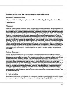
details about this UWB physical layer can be found in [5]. C. Cluster Head Design Objectives We divide SNs into two classes: (i) high-priority SNs that generate important data and at high rates, and (ii) low-priority SNs that generate less important data at lower rates. A receiver may successfully receive a data packet with a strong signal strength even if this packet is subject to interference from other packets with a lower signal strength. Hence, a high priority is assigned to a SN by placing it close to a CH, or a lower priority by placing it farther apart from CHs. Our objective is to maximize the total rate of date packets received. If the network load is light, there will be almost no overlapping of data packets, such that a CH will successfully receive most of the packets. When the load is high, CHs should receive packets only from near-by, high-priority SNs, and ignore the distant SNs. Note that packets from distant SNs would be lost anyway because of the strong interference caused by high-priority SNs close by. We illustrate our design objective with an example of a surveillance system that was originally defined in [3], see Fig. 1. An underground car park is filled with SNs of different types. Some are of low priority, such as those for temperature and humidity measurements; they generate very little traffic (< 1 kbit/s), and the loss of one or a few of their data packets is assumed to be acceptable. Other SNs are of high priority, such as seismic, infrared and microphone SNs that are used to detect movements of an intruder (≈ 10 kbit/s traffic), and cameras that transmit live videos from the area (≈ 100 − 400 kbit/s traffic). CHs are placed near high-priority SNs that are equipped with, e.g., cameras or movement detectors. When data traffic
Fig. 1. An illustration of a transmit-only sensor network in an intrusion-detection scenario. SNs are denoted by circles, CHs by crossed boxes. Empty circles are low-traffic, low-priority SNs and solid circles denote high-traffic, high-priority (e.g. video) SNs. For the CH positions indicated, the shaded areas mean potential locations for high-priority SNs.
is high, there will be many collisions between data packets. Collisions cannot be prevented because SNs are unaware of the traffic intensity. Nevertheless, if high-priority SNs are close to the CHs, interference from distant SNs is going to be low compared with the received signal power such that most of the packets from high-priority SNs will be received. In contrast, low-priority SNs may be placed significantly farther away from the CHs; their packets will be correctly received only if no intrusion is detected (i.e. if the total traffic is low), which is assumed to be sufficient for the application. A similar application is a fire-detection sensor network [6]: high-priority SNs detect fire or smoke and monitor its spread; various low-priority SNs monitor other bulding parameters such as temperature, humidity, solarization, etc. III. D ETAILED D ESCRIPTION OF T HE P ROPOSED A RCHITECTURES A. Simple CHR Architecture We first consider a CHR consisting of a noncoherent receiver in the sense of [7] and call it simple CHR: this CHR can receive only one packet at a time. While a CH is receiving a packet from a distant SN, a parallel transmission may start from a near-by, highpriority SN, because SNs are not aware of ongoing transmissions. This new transmission will interfere and can corrupt the packet being received. At the same time, the CH will not be able to receive the interfering, high-priority packet because its receiving circuit was busy when this packet transmission started. Hence, both the low- and the high-priority packet are lost. Next, we propose two simple CHR architectures that address this issue and improve performance. B. Adaptive-Threshold CHR Architecture We first describe the adaptive threshold CHR architecture. If the signal strength of the received packet is lower than the detection threshold Ed , the packet will be ignored. Otherwise, the CHR will try to receive it. We say that a packet is detected if the received signal strength is larger than Ed . The concept is illustrated in Fig. 2. Packets from SNs outside the shaded area have a received signal strength that is lower than Ed , hence they will be dropped. Only packets from SNs inside the circle will be detected. The main reason why a CH should not start receiving a low-signal-strength packet is, as explained above, that in the case of a collision, both packets will be lost. 1) Effect of Detection Threshold: To better understand the adaptive CHR, we define a simple model of the sensor network and its components, and analyze the total data throughput. First we assume that the
Rdt
Fig. 2. Illustration of the detection-threshold principle: Transmissions of SNs whose received signal strength at the CH is higher than Ed are indicated by solid lines. Transmissions of SNs whose received signal strength is below Ed are indicated by dashed lines. Only packets originating from sources within the shaded circle will be detected.
traffic generated by the SNs is Poisson-distributed. This assumption is reasonable because the optimal medium access scheme for the SNs is to defer each transmission for a random time [2]. In addition, we assume a simplified physical layer model: if a CH receives a packet from a SN with signal strength Er and if an interfering packet has the signal strength Er − ∆, then the received packet will be lost. This simplification neglects the impact of multiple interferers, but as we shall see, provides results that fit well with simulation. We consider again the scenario depicted in Fig. 2, with one CH and n randomly distributed SNs. Packets from the i-th SN, SNi , have a signal strength Er,i at the CH. The SNs generate data packets at independent random time instances that are characterized by a Poisson distribution with the rate parameter λi . The value λ = 1 corresponds to the maximum sustainable rate supported by the transmitter of a SN, called PHY rate. Hence, the total traffic load normalized to the PHY rate, that is generated by the SNs inside the circle is X λi . (1) λa (Ed ) = i:Er,i ≥Ed
We first estimate the probability that the receiver is idle at any given moment in time. The receiver is idle if it has finished decoding a preceding packet (successfully or unsuccessfully) and if no other packet has arrived in the meantime whose received signal strength is larger than the detection threshold, Ed . The state of the receiver (busy or idle) is a stationary process in time that can be described by a continuous Markov chain [8]; its stationary idle probability is given by 1 . (2) P idle (Ed ) = 1 + λa (Ed ) Next we calculate the probability that a packet transmitted by SNi will be received successfully. This
happens if the receiver is idle at the time SNi starts to transmit and if the data packet does not overlap with any packet whose received signal strength is larger than Er,i − ∆. We assume that all packets have a fixed duration Tp , which is is normalized to one, i.e., Tp = 1. Similar to non-slotted ALOHA, if a packet is sent at time zero, then any other packet arriving within the interval [−1, 1] will interfere and destroy the packet. Therefore, the probability to capture the packet of the i-th SN is X λj . (3) Pc,i (Ed ) = P idle (Ed ) exp −2 j:Er,j ≥Er,i −∆
With this, the rate of packets received from SNi is λi ∗ Pc,i (Ed ), and the aggregate throughput of all SNs normalized to the PHY rate is X λi Pc,i (Ed ). (4) X(Ed ) = i:Pr,i ≥Ed
2) Traffic Load Estimation: Now a simple method is described for tracking λa and X as well as for adapting Ed to keep the utilization, X, at a maximum. We denote with Tˆl,k the estimated average idle time of a receiver, i.e., the average time between two packets that are detected, see Fig. 4; the index k denotes the iteration step. For this purpose, we keep track of the time instants Tdet when a new packet is detected and Tend when the last detected packet ended (successfully or unsuccessfully received). With this, the average idle time can be computed iteratively as Tl,k = αTl,k−1 + (1 − α)(Tdet − Tend ).
ˆ a of the load, λa , at the k-th iteration The estimate λ can be computed as the ratio of the packet duration, ˆ a = Tp /Tl,k . Tp , to the average idle time, Tl,k , i.e., λ Tend
T end succ
Tnext_succ
Tu
111111 000000 000000 111111 000000 111111
2 11111 3 11111 00000 00000 00000 11111 00000 11111 00000 11111 00000 11111 00000 11111 00000 11111 00000 11111 00000 11111
1
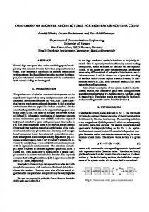
The problem of maximizing X(Ed ) can be solved numerically. We solved it for a large number of topologies and input rates, and found that the optimal value for X(Ed ) is 0.25, which is obtained if the load λa is maintained at a level of 0.75. In other words, to maximize the normalized aggregate throughput X we should estimate λa (Ed ) and vary Ed to obtain λa = 0.75.
(5)
Tl
4
5
T det
Fig. 4. An example of packet arrivals that illustrates the adaptation mechanism. Packet 1 has arrived and is received without an error. Packet 2 was being received when it collided with packet 3 and is discarded. Packet 4 is not detected because it arrives from a node outside the detection circle. Finally, packet 5 is received without an error again.
0.3
A similar estimate can be computed for the utilization X. We denote with Tˆu,k the estimated average time between two successful receptions at the k-th iteration and the time instant at the end of the last successful packet transmission, denoted with Tend succ . At the time instant when the next successful packet transmission ends, denoted with Tnext succ , we compute the update
0.25
Utilization
0.2 0.15 0.1 0.05 0 0
Tu,k = αTu,k−1 + (1 − α)(Tnext succ − Tend succ ). (6) 1
2 3 Aggregate input rate
4
5
Fig. 3. Simulation results for a network with 50 SNs uniformly distributed in a 40 m × 40 m square and one CH in the center. We plot the aggregate throughput as a function of the aggregate SN traffic load, both normalized to the PHY rate.
The above analytical model shall be verified by means of simulation. We randomly distribute 50 SNs in a 40 m × 40 m square and measure the aggregate throughput of the system for different loads. We see in Fig. 3 that the throughput is maximal when the normalized aggregate traffic load is around 0.75. At that point, the normalized aggregate throughput of the network, for simplicity called utilization, is slightly above 0.25.
ˆ of the utilization X is the ratio of the The estimate X ˆ = Tp /Tu,k . The packet duration Tp over Tu,k , i.e., X weighting parameter α is set to α = 0.95 for both, the determination of Tu and Tl . Furthermore, a CH needs to learn about existing SNs and their received signal strength. This is done during the reception of packets. Note that a CH does not necessarily need to successfully receive a whole packet to perform this task. It is sufficient to decode the header and to estimate the signal strength. A CH keeps a list of active SNs and their estimated received signal strengths {i, Er,i }i=1,···,n , sorted by descending order. The goal of the adaptive threshold algorithm is to keep the utilization at 0.25 and the detected load at
0.75. In principle, it would be sufficient to use the ˆ a , but we use both estimated load and estimated load, λ ˆ to achieve a higher robustestimated utilization, X, ness against estimation errors. The adaptive threshold algorithm is initialized with the value Ed = 0, thus even packets with the very low signal strength can be detected. The variables Tl and Tu are updated every time a packet is received, the same holds for the list of SNs and their received signal strengths. If ˆ a exceeds the level 0.75 and if at the estimated load λ ˆ drops below the same time the utilization estimate X 0.25 it can be concluded that the actual operating point is at the right side of the peak of the curve in Fig. 4, i.e., the detection threshold, Ed , is too small and has to be increased in order to decrease the traffic load λa . The detection threshold is updated every time a new packet is sensed. It is important to notice that it is more critical to chose too large a value for the detection threshold than using too small a value; this is due to the shape of the curve in Fig. 3. If we overestimate the detection threshold when the total traffic is low (points at the left from the curve’s peak), then we would further decrease the traffic load, and hence also decrease the utilization. Similarly, when the traffic load is high (points at the right from the curve’s peak) and the detection threshold is smaller than the optimum value, then both, the utilization X and the total number of detected packets are suboptimal. For this reason, we propose a conservative increase of Ed : Only if the detected load λa is larger than 0.75 and the utilization is lower than 0.25 during the reception of four consecutive packets, then the detection threshold should be increased such that one SN is removed from the SN list; in other words, if Ed = Er,i and i > 1, then we update Ed = Er,i−1 . In contrast to this, a less conservative procedure is chosen to decrease the detection threshold. The first time the detected load is lower than 0.75 and the utilization is lower than 0.25, we set Ed = Er,i+1 (if i < n, or else Ed = 0). Another important point is to keep updating Tl and Tu even if no packet arrivals are detected. Otherwise, if the traffic intensity suddenly drops or nearby SNs cease transmitting, too large a detection threshold can result. A method to avoid this is to gradually decrease the detection threshold while no packets are detected. This is achieved by setting ˆa λ
=
ˆ X
=
Tp , αTl + (1 − α)(Tdet − Tend ) Tp , αTu + (1 − α)(Tdet − Tend succ )
(7) (8)
where Tdet is the beginning time of a detected packet and Tend succ is the end of the last packet that was
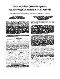
successfully received, see Fig. 4. C. Switched CHR Architecture As explained in the preceding section, a low efficiency of a CHR is mainly due to the situation that a CHR is about to receive a packet with small signal strength and during that, a packet with a stronger signal is transmitted, then the weaker packet will be destroyed due to interference and the stronger one is lost because the receiving circuit is busy. The most general way to solve this problem is to include several receiving circuits in parallel so that a CH can cope with all arriving packets. This is too expensive and not necessary in most cases. We propose a less complex receiver which consists of a simple receiver circuit and an additional acquisition circuit. This additional circuit constantly monitors the wireless medium for a newly arriving packet. If a transmission of a new packet starts and if its signal is stronger than the signal of the packet currently being received, then the CH stops receiving the current packet and switches to the new, stronger one. We call this architecture switched CHR architecture. IV. P ERFORMANCE C OMPARISON To analyze the performance of the proposed architectures we have implemented a cross-layer, discreteevent simulator that models the UWB physical layer, the multi-access schemes, and the proposed CH architectures with the greatest possible detail. A description of the simulator can be found in [9]. At the physical layer, pulses are sent with an energy level of 30 pJ. As described in [7], this implies a link data rate of 2.5 Mbit/s and a range of approximately 30 m (using the LOS propagation model from [10]). Thus all SNs can be heard by the CHs. We evaluate the performance of two networks, each having 50 SNs distributed uniformly in a 40 m × 40 m square. The first network has one CH at the center of the square, and the other two CHs located at (10 m,20 m) and (30 m, 20 m). All SNs generate Poisson traffic with the same intensity. We vary the packet-generation rate and measure the number of captured packets. The results are depicted in Fig. 5, where the performance of the two proposed architectures is compared with that of the simple CHR, defined in Subsection III-A. When the aggregate traffic rate is small, there is no difference between the three architectures, as there is almost no interference between the SNs and thus it is possible to detect and receive packets from all SNs. However, as the input rate increases above 10 Mbit/s, the performance differences become significant, and the total number of packets received by the adaptive CHR is twice that of the simple CHR. We can also
(a)
0.6 Simple Adaptive Switch
0.5
0.6
(b)
0.4 Utilization
Utilization
0.4 0.3
0.3
0.2
0.2
0.1
0.1
0 0
Simple Adaptive Switch
0.5
5
10 15 20 Aggregate input rate [Mbps]
25
0 0
5
10 15 20 Aggregate input rate [Mbps]
25
Fig. 5. Aggregate utilization X plotted as function of total load. The underlying scenario consists of 50 SNs uniformly distributed in a 40 m × 40 m square. All SNs generate Poisson traffic with the same intensity. (a) Situation with one CH located at the center of the square, (b) situation with two CHs located at (10 m, 20 m) and (30 m, 20 m).
see that in the case of the switched CHR we can in addition double the performance. Note that this improvement is achieved at the cost of a slightly more expensive hardware.
V. C ONCLUSION We described a system architecture for a low-cost UWB sensor network with transmit-only sensor nodes. As most of the design flexibility of the network is in the CHs, we proposed two novel CHR architectures that maximize the number of received packets: a so-called adaptive CHR and a switched CHR. The adaptive CHR architecture requires the same hardware as the simple, non-adaptive architecture, and therefore has almost the same implementation cost. The switched CHR architecture introduces an additional detection and synchronization circuit; it is thus expected to be more expensive. We studied the performance of the proposed CHR architectures by means of simulation and found that for low traffic load the proposed architectures perform as well as the simple CHR. For high traffic load, the switched CHR is twice as good as the adaptive CHR, which in turn is twice as good as the simple CHR. The CHR design presented in this paper is created for networks with transmit-only SNs. Our numerical results are obtained for a physical layer based on pulsed UWB radio. Nevertheless, the ideas are also applicable to other physical layers in which it is prohibitively expensive to equip each sensor node with a receiver.
ACKNOWLEDGEMENT This work was supported by the European ISTFP6 Integrated Project PULSERS (Pervasive Ultrawideband Low Spectral Energy Radio Systems; Contract No. 506897) and (in part) by the National Competence Center in Research on Mobile Information and Communication Systems (NCCR-MICS), a center supported by the Swiss National Science Foundation under grant number 5005-67322. R EFERENCES [1] W. Hirt and D. Porcino, “Pervasive Ultra-wideband Low Spectral Energy Radio Systems (PULSERS), White Paper,” Integrated Project PULSERS, http://www.pulsers.net, Nov. 2002. [2] B. Radunovic, L. Truong, and M. Weisenhorn, “On architectures of transmit-only, UWB-based wireless sensor networks,” IBM Research Report RZ 3596, 2005. [3] B. van der Wal et al., “Definition of UWB scenarios, Deliverable D2a2 - Initial,” Integrated Project PULSERS, http://www.pulsers.net, Mar. 2004. [4] M. Weisenhorn and W. Hirt, “Impact of the FCC average- and peak power constraints on the power of UWB radio signals,” IBM Research Report RZ3544, IBM Zurich Res. Lab., Sept. 2004. [5] M. Weisenhorn, “Physical layer for reader scenario,” IBM Research Report RZ 3595, 2005. [6] D. Rus, “Keynote on autonomous mobile networks,” in The First IEEE Workshop on Embedded Networked Sensors (EmNetS-I), 2004. [7] M. Weisenhorn and W. Hirt, “Robust noncoherent receiver exploiting UWB channel properties,” in Proc. IEEE Joint UWBST & IWUWBS 2004, Kyoto, May 2004, pp. 156–160. [8] P. Br´emaud, Markov Chains, Gibbs Fields, Monte Carlo Simulation, and Queues. Berlin Heidelberg: Springer-Verlag, 2001. [9] B. Radunovic, “A cross-layer system simulator for UWBbased wireless sensor networks,” IBM Research Report RZ 3594, Feb. 2005. [10] S. Ghassemzadeh and V. Tarokh, “UWB path loss characterization in residential environments,” in Proc. IEEE Radio Frequency Integrated Circuits (RFIC) Symposium, June 2003, pp. 501–504.