IOP Conference Series: Materials Science and Engineering
Related content
PAPER • OPEN ACCESS
Recent developments in Micro Friction Stir Welding: A review To cite this article: Keydon Sithole and Veeredhi Vasudeva Rao 2016 IOP Conf. Ser.: Mater. Sci. Eng. 114 012036
View the article online for updates and enhancements.
- The Effect of Tool Pin Shape of Friction Stir Welding (FSW) on Polypropylene Z C Nik, M Ishak and N H Othman - Hybrid Al/steel-joints manufactured by ultrasound enhanced friction stir welding (USE-FSW): Process comparison, nondestructive testing and microscopic analysis M Thomä, G Wagner, B Straß et al. - Effects of tool speeds and corresponding torque/energy on stir zone formation during friction stir welding/processing S Cui and Z W Chen
Recent citations - A Microstructural Evaluation of Friction Stir Welded 7075 Aluminum Rolled Plate Heat Treated to the Semi-Solid State - Micro friction stir welding of ultra-thin Al6061 sheets Yongxian Huang et al
This content was downloaded from IP address 47.8.181.20 on 12/02/2018 at 06:50
iMEC-APCOMS 2015 IOP Publishing IOP Conf. Series: Materials Science and Engineering 114 (2016) 012036 doi:10.1088/1757-899X/114/1/012036
Recent developments in Micro Friction Stir Welding: A review Keydon Sithole1*, Veeredhi Vasudeva Rao1 1 Mechanical and Industrial Engineering Department, University of South Africa, The Science Campus, Corner Pioneer / Christiaan De Wet, Florida, Roodepoort, Johannesburg 1710, South Africa
E-mail:
[email protected],
[email protected] Abstract. The advent of friction stir welding (FSW) in 1991 has been evolutionary in the joining of metals and related materials. Friction stir welding has enabled the joining of metals that could not be joined by other welding processes. Research has shown that dissimilar materials with very different properties, plastics, composites and even wood can be joined by FSW. Recent activities in the application of FSW has seen the development of micro friction stir welding (μFSW), which is the FSW of very thin sections of thickness 1000 μm (1 mm) or less. Micro friction stir welding further extends the applications of FSW to areas such as copper electrical contacts, tailor-welded blanks, wood. Though μFSW is relatively new development significant work has been done to date with interesting research findings being reported. This paper aims to review developments in μFSW to date. The focus of the paper will be on problems peculiar to μFSW due to downscaling to the micro scale and other practical considerations.
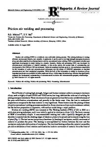
1. Introduction Friction Stir Welding (FSW) is relatively a recent metal joining process in which a hard tool, made of a pin protruding out of a shoulder, is rotated at high speed and traversed between the two pieces that are to be joined. The frictional heat generated, due to stirring action, between the work pieces and the tool shoulder and pin causes the material of the workpieces to soften and plasticize allowing the work pieces to get joined without melting of the workpiece material. The tool, comprising of pin protruding from a shoulder, generates sufficient heat which causes softening of material as it moves forward. The displaced material goes round the tool and undergoes a constrained extrusion process and gets deposited as a solid phase behind the tool, mainly on retreating side (an asymmetrical process). Heat is generated by both the shoulder and the pin mainly though friction but at the pin heat is also generated through shear. Generally most of the researchers reported three zones in the weld region namely the stir or nugget zone (SZ / NZ), the thermo-mechanically affected zone (TMAZ) and the heat affected (HAZ). 1*
To whom any correspondence should be addressed.
Content from this work may be used under the terms of the Creative Commons Attribution 3.0 licence. Any further distribution of this work must maintain attribution to the author(s) and the title of the work, journal citation and DOI. Published under licence by IOP Publishing Ltd 1
iMEC-APCOMS 2015 IOP Publishing IOP Conf. Series: Materials Science and Engineering 114 (2016) 012036 doi:10.1088/1757-899X/114/1/012036
However, some authors did not put any distinction within the TMAZ and hence cite only two zones the TMAZ and the HAZ (Galvão, et al., 2012). The stir zone is the area directly stirred by the pin. In this region there is enough heat generated to cause plastic deformation of the material and recrystallization of the grains resulting in the increase of hardness and strength in this area. The TMAZ is the area under the shoulder where the temperature is not enough for recrystallization but there is plastic deformation of the grains. In the HAZ, the area immediately on the outer side of the TMAZ, the heat is not enough to cause plastic deformation but the thermal cycles during the welding process cause some microstructure changes resulting in precipitations. The advent of friction stir welding in 1991at TWI (Teh, et al., n.d.) has been revolutionary in the joining of metals and related materials. Friction stir welding has enabled the joining of metals that could not be joined by any other welding process. Research has shown that dissimilar materials with very different properties, composites and even wood can be joined by FSW. Aluminium and its alloys are very difficult to weld because of the high thermal expansion coefficient, high thermal conductivity and high electrical conductivity (Sattari, et al., 2012). Initial FSW process was intended for the joining of aluminium and its alloys because of the limitations of the traditional welding processes on those alloys. The process has since been applied for the joining of other materials including copper, steels, and titanium in similar and dissimilar combinations. Significant advances have been made in FSW with a lot of research outputs to date focusing on, among other things materials, tools and process optimisation. Micro friction stir welding (μFSW) is an extension of FSW for joining of materials of thickness 1000 μm (1 mm) or less. Issues related to materials, defects, tools and new applications are considered. Butt and lap welds have been tried through μFSW, with a focus on butt welds (Ahmed, et al., 2014). Much of the early work on FSW focused on materials of thickness greater than 1 mm. For this thickness of materials a lot of investigations have been conducted and the relevant tools and process parameters for different similar and dissimilar materials have been established, to a large extend. Recent activities in the application of FSW has seen the development of micro friction stir welding (μFSW) at TWI (Tondi, et al., 2007), which is the FSW of very thin sections of thickness 1000 μm (1 mm) or less. Micro friction stir welding further extends the applications of FSW to areas such as copper electrical contacts (Klobčar, et al., n.d.), tailor-welded blanks (Min, et al., 2000) (Montazerolghaem, et al., 2014), wood (Tondi, et al., 2007), plastics (Panneerselvam & Lenin, 2014) and composites (Ahmadi, et al., 2012), (Prater, 2014). Though μFSW is relatively new development significant work has been done to date with interesting research findings being reported. In this paper the authors aim to review developments in μFSW to date. There is evidence that by 2005 friction stir welding of very thin sheets had been performed. Interest in FSW of very thin sheets, or micro Friction Stir Welding (μFSW) is reported as early as in 2003. The Welding Institute (TWI) laid out a project plan to conduct research into the friction stir welding on very thin lap joined aluminium sheets, which at that time had not been systematically explored (TWI, 2003). In another similar plan in 2005 the company reported accomplishment of the first phase comprising of producing lap joints and studying the effect of anodising and conversion coatings on the joints whilst starting the second phase (TWI, 2005). Developments at TWI in μFSW have been highlighted in a paper that was published on the TWI publications website (Teh, et al., n.d.). The paper discusses issues on downscaling challenges, tools and machinery for μFSW, and results of the work carried out.
2
iMEC-APCOMS 2015 IOP Publishing IOP Conf. Series: Materials Science and Engineering 114 (2016) 012036 doi:10.1088/1757-899X/114/1/012036
In the early stages of the FSW of very thin plates, there was much concern about the feasibility of the process with such small thickness of materials. As a result the early studies focused on establishing whether it was possible to conduct micro friction stir welding. Nishihara et al conducted some pilot studies to investigate the feasibility of μFSW was on AZ31 magnesium alloys (Nishibara & Nagasaka, 2004). Scialpia et al further investigated the feasibility of micro FSW but focusing on analysis of the mechanical properties of μFSW joints of 2024-T3 alloy with 6082-T6 alloy (Scialpi, et al., 2008). The alloys were successfully joined with the overall strength of the joint being very close to that of the weaker 6082-T6 alloy. The researchers in their discussion mentions eight zones in the microstructure: (1) base metal, (2) TAZ, (3) TMAZ and (4) stirred zone for the 2024 alloy and (5) stirred zone, (6) TMAZ, (7) TAZ and (8) base metal for the 6082 alloy. In another related research Scialpia et al conducted mechanical analysis of ultrathin FSW joined sheets of similar and dissimilar materials (Scialpi, et al., 2008). The researchers were able to obtain in their work excellent mechanical and fatigue properties with limited microdefects and residual stress. Even more recently Galvão et al looked at the feasibility of the process, focusing on several metals and alloys (Galvão, et al., 2012). The results obtained in the feasibility studies were encouraging, and confirmed the findings of the earlier researchers that thin plates can be welded by FSW just as well as the normal sized plates. With a careful design of welding parameters properties very close to those of the parent materials were obtained and in some cases there are even reports of improved properties. Although much of the early work in micro friction stir welding focused on butt joints of different materials, some significant strides have been made on micro friction stir lap welding. In a feasibility study of the lap joining of 2 mm thick AA1100H24 to 1 mm thick copper plates, the plates were successfully joined but the joint strength was found to be low (Elrefaey, et al., 2004). It was established that the joint strength depended on the pin tip penetration into the copper plates and increased with rotational speed. Other research projects on friction stir lap joining of similar and dissimilar materials has been conducted by different researchers (Abdollah-Zadeh, et al., 2008) (Saeid, et al., 2010.) (Xue, et al., 2011) (Akbari, et al., 2012) (Firouzdor & Kou, 2012) (Bisadi, et al., 2013). Our interest is the friction stir lap welding of materials that include very thin sections, which then falls within the scope of this present paper. Research has been conducted to investigate the friction stir lap welding of copper DHP plates of thickness 1 mm to aluminium alloys AA5083 – H111 and AA6082-T6 of thickness 6 mm (Galvão, et al., 2013). Lap joints have been shown to perform better than butt welds in tensile testing while having comparable results in hardness test for AA6XXX series aluminium alloys (Ahmed, et al., 2014). Research has seen the application of FSW in spot welding, resulting in friction stir sport welding (Yin, et al., 2010 June) (Yin, et al., 2010). With further developments this work has been extended to friction stir spot micro welding (Wang, et al., 2010). Montazerolghaem et al present in their research an approach for similar and dissimilar ultrathin tailor welded parts manufacturing, which results in very good surface polishing and mechanical properties using FSW and rolling. Results were encouraging with continuous and strong joints between the welded materials (Montazerolghaem, et al., 2014). Micro FSW has found further application in joining of wood (Tondi, et al., 2007). A weld joint was produced in wood pieces using a cylindrical spindle. Though the joint was found to be weak the feasibility was demonstrated for further development. It was established that molten material is produced in contact with the rotating tool.
3
iMEC-APCOMS 2015 IOP Publishing IOP Conf. Series: Materials Science and Engineering 114 (2016) 012036 doi:10.1088/1757-899X/114/1/012036
Sound welds were obtained in the μFSW of electrical contacts with selected welding parameters and tools (Klobčar, et al., n.d.). Surface Oxidation was noted at the oxidation temperatures. Higher strength was achieved in the weld compared to the base materials. The thickness of materials in this range is very small that this possesses some challenges that are not experienced in normal FSW. This paper aims to review developments in μFSW to date. Focus will be on problems peculiar to μFSW due to downscaling to the micro scale. Like in FSW, μFSW was initially applied to aluminium and its alloys (TWI, 2003). Applications have since been extended to other materials that include copper, brass, steels in similar and dissimilar configurations (Teh, et al., n.d.) and other materials that include plastics, composites and even wood. The problem of intermetallics that makes dissimilar joints between copper and aluminium using fusion welding difficulties can be minimised when using μFSW. This makes μFSW a very attractive process in producing aluminium and copper joints for electrical contacts. Similarly, use of μFSW in the joining of thermoplastic polymers helps reduce the problem of thermal degradation because of the lower welding temperatures.
2. Challenges in μFSW Large heat dissipation occurs from the surrounding parent material because of the high surface to volume ratio of plastic zone and increases with decreasing zone radius (Teh, et al., n.d.). This can be controlled by using an insulating but resilient backing anvil. To avoid over penetration the length of Probe should be controlled. At the same time the probe may not have complex geometries and so the heat generation from the probe is reduced. This means the shoulder friction must be compensated by providing much of the heat required for welding. For better results higher rotational speeds and lower traverse speeds may be used, which again compensates for the greater energy losses. The small size of workpieces also means greater care is needed to ensure the clamping force does not lead to deformation of the welded parts. In the same way testing equipment used should not introduce any deformations. Challenges in μFSW include reduction of mechanical resistance because of the reduction of the thickness from the tool shoulder action and reduction of joint strength due to microdefects in the welds. The occurrence of irregularities in the thickness of the weld materials has been cited as cause of failure, which occurs in the welded zone, rather than presence of defects (Scialpi, et al., 2008).
3. Tools The challenges discussed above means that some of the tools that have been successfully employed for the normal FSW may not be suitable for μFSW. Research in tools has seen the design and development of tools for μFSW (TWI, 2005) (Teh, et al., n.d.). Small tools with relevant geometries have been developed (Galvão, et al., 2013). The use of tools without pins has been under scrutiny by some researchers. Tools without pins have been used successfully. Because of the effect of the reduction of thickness on very thin section use of the tilt angle has been investigated, and in trying to control the reduction of thickness, zero tilt angles have been used. Design is important for fixtures, in μFSW, that tightly secure workpieces preventing deflection and movement during welding for sound welds. Fixtures should prevent high rates of heat conduction from the pieces to ensure there is enough heat to soften materials, especially for aluminium (Ahmed, et al., 2014).
4
iMEC-APCOMS 2015 IOP Publishing IOP Conf. Series: Materials Science and Engineering 114 (2016) 012036 doi:10.1088/1757-899X/114/1/012036
3.1. Tool geometry. Tool geometry requires consideration in producing good welds in μFSW. Besides the size of the tools, the shape and configuration of the tools should be carefully designed. Special profiles of both shoulder and the pin have been designed and employed with encouraging results. A number of researchers conduct tests using different tool geometries in experiments while keeping everything else constant and results show that use of different geometries gives rise to different results for the same materials. Important parameters in tool geometry include the shape and diameter of the shoulder; the shape, diameter and length of the pin; and the angle of tilt. Tools and machinery need to be down scaled to suitable levels for μFSW applications (Teh, et al., n.d.). Because of the small sizes μFSW requires high precision tools and fixtures (Ahmed, et al., 2014). The fixtures must firmly hold the sheets together without any deflection on the top surface and must not allow the sheets to shift during welding. The fixture must be a poor conductor so that heat generated can effectively soften the material without being conducted away too fast. Heat resistant Bakelite has been used as backing plate. Investigations have revealed that tool shoulder has more effect on properties of welds than tool pin (Rodrigues, et al., 2009 ). Use of a tool without a pin has been reported for both normal FSW and for μFSW. The results from these compares favourably especially for μFSW, where the thickness is small and enough heat is generated by use of the shoulder only (Zhang, et al., 2011). Interest in tool, material and process design for μFSW has demonstrated the large volume of patents that have been registered. This shows the enormous quest by researchers and companies to improve weld results. Research shows that since the first patent of the FSW process by TWI in 1991, over 800 patents have been registered related to μFSW and FSW till to date. Whilst tilt angle helps in holding the weld materials in place during the welding process in FSW of plates of normal thickness, the importance of the tilt angle in micro FSW is put in the spotlight. In a series of experiments with a tilt angle applied in some and no tilt angle in other experiments, it was found that there was significant reduction in the thickness compared to the base materials (Leal, et al., 2008). This significantly compromises the performance of the joint. The problem can be avoided by using tools with different designs of shoulders, like scrolled shoulders.
4. Welding parameters Welding parameters play a very important role in FSW. The main parameters that need special consideration include the tool rotational speed and the traverse speed (Ahmed, et al., 2014). Welding parameters affect such things as material flow, material mixing in dissimilar μFSW, microstructure in the weld area, and mechanical engineering properties including hardness, tensile and compressive strength, ductility and brittleness; impact and fatigue strength. The effects of FSW of thin sections of different materials on these properties have been investigated by different researchers using different analysis tools. Different rotational speeds of up to 3000 rpm and traverse speed between 50 to 500 mm/min have been applied for different materials in μFSW to obtain sound welds (Teh, et al., n.d.). Rotational speed has been cited as the most significant factor for producing sound FS welds (Vijayan, et al., 2010).
5. Microstructural evaluation Fine grained microstructure without segregation and coarse grains were obtained in μFSW welds for both butt and lap joints just as in the larger scale FSW joints (Teh, et al., n.d.). Researchers have been
5
iMEC-APCOMS 2015 IOP Publishing IOP Conf. Series: Materials Science and Engineering 114 (2016) 012036 doi:10.1088/1757-899X/114/1/012036
able to establish that the grain structure in different zones will be different in μFSW, which tallies with findings in FSW. 5.1. Grain size Grain size affects the mechanical properties such as hardness and strength. Both properties generally increase with decrease in size of the grains. Smaller grain size results from use of lower temperatures since grain growth is fostered by higher temperatures. As a result soft materials tend to experience an improvement in these properties during FSW as a result of lower welding temperatures. For harder materials higher frictional forces are required before the material can begin to plasticize and as a result higher temperatures are required, which means the grain sizes are not as small and properties may then not be as much improved compared to the parent materials. Grain size is not the only factor that affects the hardness of materials. In age-hardened alloys, precipitation during formation of the alloy results from the ageing during the solidification process. Hardening in these alloys result because precipitates lodge in dislocations and prevents the easy flow of the material. In FSW of age-hardened alloys it is important to take note that hardness and strength might be reduced in such materials even with small grain structure. This is because of the dissolution of precipitates during the FSW process, which is greater than the hardening resulting from the reduced grain size. This has been noted and reported in both similar and dissimilar FSW of materials. 5.2. Nugget zone (stirred zone, SZ) As indicated before the microstructure in this zone results from recrystallization of plasticized material. Because of the welding temperatures that are lower than the melting point, very small grains are formed that improves properties of the welds. Formation of Onion ring structures were reported in some combinations of similar and dissimilar materials but are absent in other (Rodrigues, et al., 2009 ), (Leal, et al., 2008). 5.3. Spherical zone It has been found that when the tool is withdrawn the material surrounding the hole left by the pin, the spherical zone has extremely fine grained microstructure (Leal, et al., 2008). This is a result of the interaction of the material and the pin due to the stirring action. This region is undesirable in components and this area is either cut off or is designed out during the welding process. However it is worth noting that there is such an effect on the material that is immediately around the pin. 5.4. Thermo-Mechanically Affected Zone Material in this zone does not recrystallization because the heat in this zone is not high enough. However the material experiences plastic deformation due to heat and some microstructure changes occur. As a result the properties of the material in this region will be different from the parent materials. An interesting phenomenon was reported in two researches on μFSW of dissimilar materials between aluminium and copper alloys. In an investigation on the FSW of aluminium alloys AA6016 –T4 and AA 5182-H111 a tongue of material white was found going upwards on the advancing side into the AA5182 material (Leal, et al., 2008). A similar tongue was found in the similar μFSW of AA6016 T4 alloy (Rodrigues, et al., 2009 ) and in the dissimilar FSW of tongue of grey material going upwards
6
iMEC-APCOMS 2015 IOP Publishing IOP Conf. Series: Materials Science and Engineering 114 (2016) 012036 doi:10.1088/1757-899X/114/1/012036
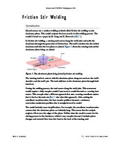
through advancing side of weld was reported for 750 rpm rotational speed and feed rate 160 mm/min copper on advancing side (Galvão, et al., 2010). The diagram Fig 1 and Fig 2 below show tongue of material.
Fig 1: Transverse cross-section of S-750_16_Cu weld (Galvão , Leal , Loureiro , & Rodrigues, 2010)
Fig 2: Material tongue (Galvão , Leal , Loureiro , & Rodrigues, 2010) 5.5. Heat-Affected Zone In this zone the heat is enough to cause plastic deformation but microstructural changes occur in the material. Properties of the material in this zone are closer to the parent materials than the other zones.
6. Properties 6.1. Hardness In the study on μFSW of aluminium, copper, brass and zinc alloys (Galvão, et al., 2012), hardness in the TMAZ for brass was noted to be higher than in the parent material which the authors attributed to the much reduced grain size. In contrast, in the HAZ coarse grain structure was observed resulting hardness lower than the base material. For the copper the hardness was found to increase due to grain refinement in the TMAZ with a slight softening in the HAZ, which agrees with the findings of other researchers (Xie, et al., 2007) in their study on thick plates of copper. The aluminium alloys registered no significant changes in the hardness of the welds compared to the parent materials, but the results were due to different factors. In the non-heat treatable 5182-H111 this result from the compensating annealing effect on the hardening resulting from plastic deformation and this same result was also exhibited in the welds on zinc. For aluminium, tensile strength in lap joints is better than in butt joints. For hardness tests, performance of transverse and longitudinal samples was found to be comparable to that of the parent materials. 7
iMEC-APCOMS 2015 IOP Publishing IOP Conf. Series: Materials Science and Engineering 114 (2016) 012036 doi:10.1088/1757-899X/114/1/012036
6.2. Strength and ductility In the analysis of aluminium, copper, brass and zinc alloys (Galvão, et al., 2012) an inferior elongation was noted for all the welds. Ductility was found to be good; yield stress was comparable in the welds and the parent materials whilst tensile strength was noted as under match for all except zinc welds. The anomaly in the zinc was attributed to the kissing bond defect. Brass was found to fail in the base metal before plastic deformation of the TMAZ whilst 6016-T4 failed in the welds. The reduction of thickness or kerfs effect of the striations has been identified as the reason for location of the fracture. Tensile strength for Al alloys has been found to be generally lower than in parent material for different types of welding tools (Rodrigues, et al., 2009 ) whilst formability has been found to be similar to base material.
7. Discussion The study by Galvao et al focusing on several metals is important in showing that comparison of different metals under similar conditions is not very conclusive (Galvão, et al., 2012). There is need to optimise welding parameters for each material. The study showed that the materials have different mechanisms influencing grain size formation and resulting hardening or softening. The authors highlighted such processes as annealing, precipitate dispersion, coarse hardening occurring in different specimen and this means control of properties for different materials depends on control of different weld parameters. This highlights the need for more research to characterise and model the different materials and combinations of materials, in the case of dissimilar FSW, so as to optimise performance characteristics of the welds. From this stand point it can be concluded that it is important to find the optimum operating conditions for each material/tool combination (Lakshminarayanan & Balasubramanian, 2008), (Peel, et al., 2003), (Hirata, et al., 2007).
8. Conclusion The process of FSW has been shown to be successful in the joining of thin materials. This review has looked at the work of different researchers and very positive results have been obtained with different similar and dissimilar materials using a wide variety of tools and tool configuration. It should be noted that the optimum conditions for different materials and tools vary. Whereas comparisons are made for different combinations of materials and conditions, the results may not reveal the full set of possible outcomes. If possible the investigation should include the optimum conditions for all the tools under consideration. In some cases it may be necessary to include a post-welding treatment to achieve better results.
8
iMEC-APCOMS 2015 IOP Publishing IOP Conf. Series: Materials Science and Engineering 114 (2016) 012036 doi:10.1088/1757-899X/114/1/012036
9. References and Bibliography Abdollah-Zadeh, A., Saeid, T. & Sazgari, B., 2008. Microstructural and mechanical properties of friction stir welded aluminium/copper lap joints. Journal of Alloys and Compounds, Volume 460, p. 535–538. Ahmadi, H., Mostafa Arab, N. B., Ashenai Ghasemi, F. & Eslami Farsani, R., 2012. Influence of Pin Profile on Quality of Friction Stir Lap Welds in Carbon Fiber Reinforced Polypropylene Composite. International Journal of Mechanics and Applications, 2(3), pp. 24-28. Ahmed, S., Shubhrant, A., Deep, A. & Saha, P., 2014. Development and Analysis of Butt and Lap welds in Micro Friction Stir Welding (μFSW),. Guwahati, Assam, India, AIMTDR, pp. 563-1 - 563-5. Akbari, M., Abdi Behnagh, R. & Dadvand, A., 2012. Effect of materials position on friction stir lap welding of Al to Cu. Science and Technology of Welding and Joining, Volume 17, p. 581 – 588. Bisadi, H., Tavakoli, A., Sangsaraki, M. T. & Sangsaraki, K. T., 2013. , 2013. The influences of rotational and welding speeds on microstructures and mechanical properties of friction stir welded Al5083 and commercially pure copper sheets lap joints.. Materials & Design, Volume 43, pp. 80-88. Elrefaey, A., Takahashi, M. & Ikeuchi, K., 2004. Microstructure of aluminium/copper lap joint by friction stir welding and its performance. Journal of High Temperature Society, Volume 30, p. 286– 292. Firouzdor, V. & Kou, S., 2012. Al-to-Cu friction stir lap welding. Metallurgical and Materials Transactions A, Volume 43A, pp. 43A, 303–315. Galvão, I., Leal, R. M., Loureiro, A. & Rodrigues, D. M., 2010. Material flow in heterogeneous friction stir welding of aluminium and copper thin sheets. Science and Technology of Welding and Joining, p. 654 – 660. Galvão, I., Leal, R. M., Rodrigues, D. M. & Loureiro, A., 2013. Influence of tool shoulder geometry on properties of friction stir welds in thin copper sheets. Journal of Materials Processing Technology, Volume 213, p. 129–135. Galvão, I., Leitão, C., Loureiro, A. & Rodrigues, D., 2012. Friction Stir Welding of very thin plates. Soldagem & Inspeção. Galvão, I. et al., 2013. Influence of aluminium alloy type on dissimilar friction stir lap welding of aluminium to copper. Journal of Materials Processing Technology, p. 1920– 1928. Hirata, T., Oguri, T. & Hagino, H., 2007. Influence of friction stir welding parameters on grain size and formability in 5083 aluminum alloy. Journal of Materials Science and Engineering, Volume A 456, p. 344–349.. Klobčar, D. et al., n.d. Micro Friction Stir Welding of copper electrical contacts. Tušek, Milan Bizjak, Matija Bušić, pp. 167 - 174.
9
iMEC-APCOMS 2015 IOP Publishing IOP Conf. Series: Materials Science and Engineering 114 (2016) 012036 doi:10.1088/1757-899X/114/1/012036
Lakshminarayanan, K. & Balasubramanian, V., 2008. Process parameters optimization for friction stir welding of RDE-40 aluminum alloy using Taguchi technique, , Vol.18, pp. .. Transactions of NonFerrous Metal Society of China, pp. 548-554. Leal, R. M. et al., 2008. Material flow in heterogeneous friction stir welding of thin aluminium sheets: Effect of shoulder geometry. Materials Science and Engineering, p. 384–391. Leal, R. M. et al., 2010. Effect of shoulder cavity and welding parameters on friction stir welding of thin copper sheets. Science and Technology of Welding and Joining. Leitão, C. et al., 2009. Mechanical behaviour of similar and dissimilar AA5182-H111 and AA6016-T4 thin friction stir welds. Materials and Design, p. 101–108. Min, K. B., Kim, K. S. & Kang, S. S., 2000. A study on resistance welding in steel sheets using a tailor-welded blank. Journal of Materials Processing Technology, p. 186–192. Montazerolghaem, H., Tehrani, A. F. & Badrossamay, M., 2014. An Innovative Approach for Manufacturing of Thin Welded Blanks and Coils. Materials and Manufacturing Processes, pp. 889893. Nishibara, T. & Nagasaka, Y., 2004. Development of Micro-Friction Stir Welding. Metz, France, s.n. Panneerselvam, K. & Lenin, K., 2014. Joining of Nylon 6 plate by friction stir welding process using threaded pin profile. Materials and Design, p. 302–307. Peel, M., Steuwer, A., Preuss, M. & Withers, P., 2003. Microstructure, mechanical properties and residual stresses as a function of welding speed in aluminium AA5083 friction stir welds. Acta Materialia, Volume 51, pp. 4791-4801. Prater, T., 2014. Friction Stir Welding of Metal Matrix Composites for use in aerospace structures. Acta Astronautica, p. 366–373. Rodrigues, D. M. et al., 2009 . Influence of friction stir welding parameters on the microstructural and mechanical properties of AA 6016-T4 thin welds. Materials and Design, p. 1913–1921. Saeid, T., Abdollah-Zadeh, A. & Sazgari, B., 2010.. Saeid, T., Abdollah-Zadeh, A., Sazgari, B., Weldability and mechanical properties of dissimilar aluminium – copper lap joints made by friction stir welding. .. Journal of Alloys and Compounds, Volume 490, p. 652–655. Sattari, S., Bisadi, H. & Sajed, M., 2012. Mechanical Properties and Temperature Distributions of Thin Friction Stir Welded Sheets of AA5083. International Journal of Mechanics and Applications , 2(1), pp. 1-6. Scialpi, A., De Filippis, L. A. C., Cuomob, P. & Di Summa, P., 2008. Micro friction stir welding of 2024-6082 aluminium alloys. Welding International, p. 16–22. Scialpi, A. et al., 2008. Mechanical analysis of ultra-thin friction stir welding joined sheets with dissimilar and similar materials. Materials and Design, p. 928–936.
10
iMEC-APCOMS 2015 IOP Publishing IOP Conf. Series: Materials Science and Engineering 114 (2016) 012036 doi:10.1088/1757-899X/114/1/012036
Simoncini, M. & Forcellese, A., 2012. Effect of the Welding Parameters and Tool Configuration on Micro- and Macro-mechanical Properties of Similar and Dissimilar FSWed Joints in AA5754 and AZ31 Thin Sheets, ., , 41, p. Materials Design, Volume 41, p. 50–60. Teh, N. J., H, G. & Whitaker, A., n.d. Developments in micro applications of friction stir welding. Dense, pp. 1-18. Tondi, G., Andrews, S., Pizzi, A. & Leban, J. M., 2007. Comparative potential of alternative wood welding systems, ultrasonic and microfriction stir welding. Journal of Adhesion Science and Technology, pp. 1633-1643. TWI, 2003. Group sponsored project 15718 (Ex: PR8485): Friction stir welding of thin aluminium sheets. [Online] Available at: http://www.twi-global.com/EasysiteWeb/getresource.axd?AssetID=55446 [Accessed 21 07 2015]. TWI, 2005. Group sponsored project 15718 (Ex: PR8485): Friction stir welding of thin aluminium sheets – phase II. [Online] Available at: http://www.twi-global.com/EasysiteWeb/getresource.axd?AssetID=55437 [Accessed 21 07 2015]. Vijayan, S., Raju, R. & Rao, S. R. K., 2010. Multiobjective optimization of friction stir welding process parameters on aluminium alloy AA 5083 using Taguchi-based Grey relation analysis. Materials and Manufacturing Processes, 25(11), pp. 1206-1212. Wang, D. A., Chao, C. W., Lin, P. C. & Uan, J. Y., 2010. Mechanical characterization of friction stir spot microwelds. Journal of Materials Processing Technology, Volume 210, p. 1942–1948. Xie, G. M., Ma, Z. Y. & Geng, L., 2007. XIE, G.M.; MA, Z.Y.; GENG, L. Development of a finegrained microstructure and the properties of a nugget zone in friction stir welded pure copper. Scripta Materialia. Xue, P. et al., 2011. Achieving high property friction stir welded aluminium/copper lap joint at low heat input. Science and Technology of Welding and Joining. Volume 16, p. 657–661. Yin, Y. H., Sun, N., North, T. H. & Hu, S. S., 2010 June. Microstructures and mechanical properties in dissimilar AZ91/AZ31 spot welds. Materials Characterization, Volume 61, p. 1018–1028. Yin, Y. H., Sun, N., North, T. H. & Hu, S. S., 2010. Hook formation and mechanical properties in AZ31 friction stir spot welds. Journal of Materials Processing Technology, Volume 210, p. 2062– 2070. Zhang, L. et al., 2011. Friction Stir Welding of Al Alloy Thin Plate by Rotational Tool without Pin. Journal of Material Science and Technology, p. 647 – 752.
11