software tools must reliably address ship performance issues such as ... Past performance experiences of the tools. ... nonlinear free surface boundary condition and iterative sinkage ..... wet during testing, the dimensional scan revealed no.
10th International Symposium on Practical Design of Ships and Other Floating Structures Houston, Texas, United States of America © 2007 American Bureau of Shipping
Recent Hydrodynamic Tool Development and Validation for Motions and Slam Loads on Ocean-Going High-Speed Vessels Woei-Min Lin 1), Matthew Collette 1), David Lavis 2), Stuart Jessup 3), John Kuhn 4) 1)
Science Applications International Corporation, Advanced Systems and Technology Division Bowie, Maryland, USA 2) CDI Marine, Systems Development Division Severna Park, Maryland, USA 3) Naval Surface Warfare Center, Carderock Division Bethesda, Maryland, USA 4) Science Applications International Corporation, Naval Hydrodynamics Division San Diego, California, USA
Abstract The marine community continues to push the boundaries of high-speed marine transportation, with both commercial and military operators seeking potential solutions for the safe and economic transportation of time-sensitive cargos on trans-oceanic routes. The design of such vessels becomes more complex when operational requirements dictate the use of shallow-draft ports with minimal supporting infrastructure. To provide the naval architect with a set of practical tools to design this type of vessel, the Office of Naval Research (ONR) commissioned, in 2005, several development and validation research projects as part of a high-speed sealift (HSSL) program. This paper presents the results of several key studies covering hullform development, prediction of unsteady motions and hull structural loads, model tests, and code validation undertaken by the SAIC-led HSSL research team.
Keywords HSSL; High-speed; Sealift; Computation; Hydrodynamics; Simulation; Model test; Validation.
Introduction There is continued interest in military circles for highspeed vessels that can combine trans-oceanic range with high sustained speed, yet still access austere ports. There are many challenges to designing such a vessel; one central challenge is obtaining reasonable estimates of the hydrodynamic performance of candidate hullforms. The primary objective of the SAIC-led HSSL effort was to assemble, evaluate, extend, and validate a set of software tools for the hydrodynamic design and performance assessment of HSSL ships. This set of software tools must reliably address ship performance
issues such as unsteady motions and wave loads, impact loads, resistance, added resistance, maneuvering, viscous effects, and shallow-water effects. This set of tools must also handle innovative design features that may be used on such vessels, including multi-hull, SES (Surface Effect Ship), and waterjet propulsion. To test the ability of this set of software tools, an innovative multi-hull vessel (HSSL hullform) design was developed that meets the ONR’s design objectives. This HSSL hullform design combines aspects of catamaran, SES, and SWATH (Small Water plane Area Twin Hull) technology. It is capable of transporting 4,000 short tons of payload at high speed (43 knots) on trans-oceanic voyages, completing at-sea cargo transfers, and entering ports with less than 6.5m available water draft. Minimizing resistance, and hence deadweight consumed by fuel, was identified early on as a key design challenge in this effort. Building on the preliminary design developed by CDI Marine’s Systems Development Division (CDIM-SDD), a process for resistance reduction through computational shape optimization was used. Subsequent integration of the resistance predictions with high-fidelity codes into the design optimization procedure was carried out by CDIM-SDD to develop the final HSSL hullform for model tests and code evaluations. Model tests of the HSSL hullform were carried out at the Naval Surface Warfare Center Carderock Division (NSWCCD) to show the ship’s performance characteristics and to generate validation data for the software tools. The tests were done at all three operation modes: catamaran, SES, and SWATH. In addition, a scale-model of the Sea Fighter hullform was also tested to generate a selected set of maneuvering force data and wetdeck slamming pressure using novel slam panels developed at NSWCCD. The software tools selected and evaluated in this effort include ComPASS (Commercial Parametric Assessment
of Ship Systems), Das Boot, VERES, LAMP (the Large Amplitude Motion Program), FANS (Finite-Analytic Navier-Stokes), and SHAPE. These software tools were validated to the extent possible and extended based on specified program needs. More detailed description of these software tools, the HSSL hullform design, the hullform optimization process, model tests, validation results, lessons learned, and recommendations for future development are presented in this paper.
Software Tool Set for Design and Performance Predictions The primary objective of the HSSL effort was to assemble, evaluate, extend, and validate a set of software tools for design and performance assessment of HSSL ships. The software tools were selected based on ONR’s target performance prediction capabilities. The following criteria were used: Capabilities that are needed for HSSL ship design and performance analysis Physics-based rather than empirical approaches Maturity of capabilities and readiness to be used for its intended purposes Past performance experiences of the tools. The major selected software tools and their intended functions are shown in Table 1 below.
FANS
LAMP
VERES
Code Capabilities Unsteady motions and loads in waves Wave resistance Added resistance Water-jet propulsion Maneuvering Shallow water effects Multi-hulls Surface-effect ship Viscous effects
Das Boot
Selected Software Tools in the HSSL Program
ComPASS
Table 1:
In addition to the software tools listed in the table, a shape optimization code, SHAPE, was also used. SHAPE can be used with all the codes described in the table for hullform optimization. A brief description of each one of the software tools and their roles in the HSSL program is given below. ComPASS ComPASS is an acronym for “Commercial Parametric Assessment of Ship Systems”. This software represents a unique design tool for navigating the ship design space. It has been widely validated and utilized in
support of many government programs, building upon a long legacy (28+ years) of design synthesis module development at CDIM-SDD. The technical goals driving the software development were to provide early concept exploration and platform optimization, and to improve the process of evaluating the cost and potential technical benefits of newly emerging technologies to the overall ship system and the fleet as a whole. During the development of ComPASS, the overall objective was to establish a design synthesis tool that recognizes current or projected future fleet requirements and operational priorities, and permits a realistic assessment of the cost benefits and “whole-ship” impacts of emerging technologies. Other common uses of the model include those in which the cost impact of changing operational requirements, such as vessel speed and range, are easily examined, and those in which “design-to-cost” trade-offs are conducted to determine the preferred selection of hullform, structural materials, and subsystem choices. In the HSSL effort, ComPASS was the primary engine used for the HSSL hullform design. It was used first for the baseline HSSL hullform design and then with the embedded resistance surrogate model from Das Boot to produce the final HSSL hullform. Das Boot Das Boot is a de-singularized potential flow code with a nonlinear free surface boundary condition and iterative sinkage and trim. It is used for the analysis of steady speed performance in calm water for various types of surface vessels, including monohulls, catamarans, and trimarans. A version of the code with lift is available. Wave resistance is calculated by both pressure integration and wave cut analysis. Skin friction drag is estimated with friction line methods, and form drag is estimated with a form factor. Das Boot has undergone extensive validation based on tank test data. More detail about Das Boot can be found in Wyatt (2000). In the HSSL effort, Das Boot was the primary code for ship resistance prediction. It was used extensively with SHAPE for the HSSL hullform optimization. VERES VERES (Vessel Responses) is a strip theory program for predicting ship motions and loads with several extensions to increase accuracy for high-speed craft. VERES implements both conventional strip theory established by Salvesen, Tuck, and Faltinsen (1970), and the high-speed strip theory developed by Faltinsen and Zhao (1991), which extends the accuracy of conventional strip theory to higher speeds by considering the interaction effects between strips (this theory is also known as 2½D theory). Further extensions to the high-speed theory are available, which include hull interaction effects for catamarans. The basic version of the VERES is implemented as a linear, frequency-domain code that generates standard response amplitude operators (RAOs) for both motions and load responses. VERES is capable of calculating global
resultant loads in both longitudinal and transverse directions, and can also account for torsional loading. Empirical add-on models are available for viscous roll damping, foils, and slamming pressure predictions. Both short and long-term post-processors are available for making statistical motion and load prediction in specific sea-states and for a given operational scatter diagram and operational profile. A time-domain solver is also implemented, which allows non-linearities from hydrostatic and Froude-Krylov forces to be estimated. LAMP The Large Amplitude Motions Program is a timedomain simulation model specifically developed for computing the motions and loads of a ship operating in extreme sea conditions. LAMP System development began with a 1988 DARPA project for advanced nonlinear ship motion simulation, and has continued under the sponsorship of the U.S. Navy, the U. S. Coast Guard, the American Bureau of Shipping (ABS), and SAIC’s IR&D program. LAMP has been used extensively for performance assessment of ship motions and wave loads in the past 15 years (Shin et. al., 2003). LAMP uses a time-stepping approach in which all forces and moments acting on the ship, including those due to wave-body interaction, appendages, control systems, and green-water-on-deck, are computed at each time step and the 6-DOF equations of motions are integrated in the time-domain using a 4th-order RungeKutta algorithm. In addition to motions, LAMP also computes main hull-girder loads using a rigid or elastic beam model and includes an interface for developing Finite-Element load data sets from the 3D pressure distribution. The core of the LAMP System is the 3D solution of the wave-body interaction problem in the time-domain (Lin and Yue, 1990, 1993). A 3D perturbation velocity potential is computed by solving an initial boundary value problem using a potential flow boundary element or “panel” method. A combined body boundary condition is imposed that incorporates the effects of forward speed, the ship motion (radiation), and the scattering of the incident wave (diffraction). The potential is computed using either a hybrid singularity model that uses both transient Green functions and Rankine sources (Lin et al., 1999), or a Rankine singularity model with a damping beach condition. Once the velocity potential is computed, Bernoulli’s equation is used to compute the hull pressure distribution, including the second-order velocity terms. The perturbation velocity potential can be solved over either the mean wetted surface (the “body linear” solution) or over the instantaneously wetted portion of the hull surface beneath the incident wave (the “body nonlinear” approach). In either case, it is assumed that both the radiation and diffraction waves are small compared to the incident wave and the incident wave slope is small so that the free-surface boundary conditions can be linearized with respect to the incidentwave surface. Similarly, the incident wave forcing (Froude-Krylov) and hydrostatic restoring force can also
be computed either on the mean wetted surface or on the wetted hull up to the incident wave. The combinations of the body linear and body nonlinear solutions of the perturbation potential and the hydrostatic/Froude-Krylov forces provide multiple solution “levels” for the ship-wave interaction problem. These levels are: LAMP-1 (body linear solution): both perturbation potential and hydrostatic/Froude-Krylov forces are solved over the mean wetted hull surface LAMP-2 (approximate body nonlinear solution): the perturbation potential is solved over the mean wetted hull surface while the hydrostatic/FroudeKrylov forces are solved over the instantaneous wetted hull surface LAMP-3 (approximate body nonlinear solution with large lateral displacements): similar to LAMP2, but the hydrodynamic formulation is revised so that large lateral displacements and yaw angles are accounted for; this allows accurate maneuvering simulations LAMP-4 (Body nonlinear solution): both the perturbation potential and the hydrostatic/FroudeKrylov forces are solved over the instantaneous wetted hull surface. For most seakeeping problems, the most practical level is the “approximate body-nonlinear” (LAMP-2) solution, which combines the body-linear solution of the perturbation potential with body-nonlinear hydrostaticrestoring and Froude-Krylov wave forces. This latter approach captures a significant portion of nonlinear effects in most ship-wave problems at a fraction of the computational effort for the general body-nonlinear formulation. However, body-nonlinear hydrodynamics and nonlinear incident wave effects can be important, depending on ship geometry and operating conditions. Other than the ship motions and wave loads calculations, LAMP also has extensive capabilities for solving many ship hydrodynamics and dynamics related problems such as impact loads, whipping responses, wetdeck slamming loads, green water effects (Liut et al., 2002; Zhang et al., 2005), parametric roll (Shin et al., 2004) ship maneuvering in calm water and in waves (Lin et. al., 2006), and ship-ship interactions (Zhang et al., 2007). Even though LAMP is a potential-flow based program, it has the ability to incorporate external force models and has been used extensively as a dynamic simulation tools for marine vehicles. LAMP was the primary code in the HSSL program for prediction of ship motions, wave loads, impact loads, added resistance in waves, and maneuvering. Under the program, LAMP was further developed to include the waterjet propulsion capability, to provide an initial SES modeling capability, and to use pre-corrected Fast Fourier Transfer (pFFT) method for an order of magnitude computation speedup of body nonlinear hydrodynamics calculations and problems involving large number of panels (>10,000).
FANS The FANS code was developed by Dr. H.C. Chen at Texas A&M University (Chen and Yu, 2006; Pontaza et al., 2005). It consists of the following main components: (1) finite-analytic method for the solution of compressible and incompressible Reynolds-Averaged Navier-Stokes (RANS) equations and energy equation in general curvilinear coordinates; (2) dynamic chimera domain decomposition technique for overlapped, embedded, or matched grids including relative motions; (3) near-wall Reynolds stress (second-moment) and two-layer k- turbulence models for turbulent boundary layer and wake flows; (4) large eddy simulation for unsteady chaotic eddy motions; (5) linear and nonlinear wave effects; (6) level-set method for interfacecapturing between two different fluids; (7) detailed propeller flow simulations or interactive coupling with propeller performance programs; (8) coupling with sixdegree-of-freedom motion program for ship, structure, wave, and current interactions; and (9) multi-processor parallelization for large-scale CFD applications. The combination of these methods provides a unique capability for modeling complex fluid flow and heat transfer, including viscous and violent free surface effects, around practical three-dimensional configurations. The FANS code has been used for a wide range of applications including the ship berthing operations, modular hybrid pier and multiple ship interactions, ship-ship interactions in navigation channel, unsteady propeller flow analyses under design and off-design operations, complete propeller-ship flow simulations, vortex-induced vibrations, green water effects, dam breaking, tank sloshing, bridge pier scour, abutment scour, channel migration, and internal cooling and film cooling of turbine blades. SHAPE The SHAPE code (Kuhn et al., 2007) is a geometric hullform optimization tool that has been under periodic development by SAIC since the early 1990s. The optimization technique is based on sequential linear programming, and the geometric model is based on a series of basis functions that are added to a baseline design. The coefficients of the basis functions are the unknowns of the optimization problem. The SHAPE code finds values for these unknowns that minimize a user-defined objective function subject to user-defined constraints. A generic architecture is available for the objective function and constraints. This allows the use of virtually any tool for their calculation. To facilitate this, each basis function is individually applied to the baseline design and the resulting series of hulls is evaluated by whatever tool is desired. The results of the evaluations are then used to derive the influence of each basis function on the metric that is calculated by the tool. The influence of each basis function is formulated as a derivative with respect to the coefficient of the basis function. For each metric of interest, these derivatives are used to define a Taylor Series Expansion about the point in design space that is defined by the
baseline design. Having done this, each expansion is then input to the SHAPE code via the objective function or a constraint. The SHAPE code also contains an assortment of relatively common objective functions and naval architectural constraints. In combination with the generic architecture described above, the code is capable of performing a broad range of optimization tasks. It has been used for ship design and yacht design with objective functions based on isolated metrics (such as wave resistance), and also integrated metrics that involve comprehensive performance simulation. The SHAPE code, together with the Das Boot code, was used for HSSL hullform shape optimization in the HSSL program.
HSSL Hullform Design The ability of the software tools was tested on an innovative multi-hull HSSL hullform. This HSSL hullform was designed to a demanding set of performance targets (speed ≥ 43 knots, un-refueled range ≥ 5000 nautical miles, payload ≈ 4000 tons, draft at port entry ≤ 6.5m, and full performance through at least sea state 4) necessitating a short overall length (~170m), high installed power, and the ability to function as a SWATH to reduce motions. Thus, the concept vessel features a hybrid catamaran-SWATHSES hull shape as shown Fig. 1. The vessel is designed to transit at 43 knots, which gives a full-load condition Froude number of 0.542. A baseline hullform design was developed at the beginning of the program by CDIM-SDD using ComPASS, and the hullform design evolved during the course of the HSSL program. Fig. 2 shows a photograph of the final hull surface from a scale model built to test the vessel’s motions, and Table 2 lists the main particulars of the design. The most notable step in the design process was hullform optimization to reduce drag using a highfidelity resistance code, Das Boot, and the shape optimization code, SHAPE. To meet the demanding set of design objectives, it was necessary to reduce the total drag. SHAPE and Das Boot were used to optimize the hullform to minimize the total drag at 43 knots in calm water. Although SHAPE is capable of enforcing large numbers of design constraints, they were intentionally avoided for this particular application because the HSSL concept was at a very early stage in the evolution of its design. It is beneficial to allow the optimization process to freely explore design space without the limitations that are imposed by constraints; this allows the process to fully exploit various elements of physics, including concept-specific issues such as hull-hull interaction. Since some of these issues are relatively unusual, it is no surprise that the optimal hullform has a somewhat unusual geometry. In the shape optimization process, only three constraints are enforced based on SES operational goals:
Draft is prevented from increasing Displaced volume beneath the 21.3 foot waterline is prevented from decreasing The inboard hull surface above the 21.3 foot waterline is not included in optimization. The total drag of the final hullform is about 25% less than the original baseline design at the design speed. It is worthwhile to note that although the shape optimization was done to minimize total drag only at 43 knots, the total drag of the optimized hullform is lower than that of the original baseline design at all speed tested (20 – 43 knots). A particular challenge of this hullform is the step-like transition between catamaran and SWATH hullforms that occurs just above the full-load still waterline. This rapid transition and the high forward speed of the vessel mean that a time-domain non-linear motion and load simulation is most suited for analysis of this concept.
Fig. 1: Section View of the Conceptual HSSL Hullform
Fig. 2: View of the HSSL Hullform Table 2:
Key Parameters of the HSSL Design
Parameter LOA LWL Beam Overall Displacement Transit Speed
Value 179.0m 170.1m 45.0m 19,630mt 43 Knots
to validate key performance parameters of the HSSL hullform. In addition, model tests were carried out using the 1/15th scale Sea Fighter model to collect additional validation data. These two model test programs are described briefly below. HSSL Hullform Model Test The HSSL model test program represents a comprehensive data set for code validation with a numerically challenging hullform that can be used as an SES, catamaran, SWATH, or SWATH hull stabilized by SES cushion. A brief overview of the model test and data available is presented in this section. A 1/55th scale model of the vessel was tested at the NSWCCD high-speed tank in December 2006. The model test program consisted of 282 runs, covering motions and resistance in all three operational modes. Fig. 3 shows snap shots of the model test in different modes. Both regular and irregular seas runs were made for the catamaran high-speed transit mode at 25 knots and 43 knots. Irregular seas runs were made for the SWATH mode at 0 knots, 5 knots, and 10 knots, both with and without the SES cushion deployed. Calmwater resistance runs were made for the catamaran mode and SES shallow-draft mode over the range of speeds that each mode operates in. For each run, the following data was recorded at a 50Hz sampling speed: carriage speed, wave height at probe location, drag force, heave displacement, pitch displacement, vertical acceleration at the bow, vertical acceleration at the C.G., vertical acceleration at the stern, pitch rate, roll rate, and cushion pressures in the SES cushion and seals. In addition, all runs were videotaped at three angles, showing the profile of the vessel as well as bow and stern views. Digital photographs were taken of the model set-up, test configuration, and several of the runs. After the completion of testing, the model was laserscanned and the dimensions were compared to the specified dimensions. With the exception of some local swelling of the model where the unfinished interior got wet during testing, the dimensional scan revealed no significant discrepancies from the specified dimensions. Selected resistance runs were repeated during the experiment after the swelling was discovered, and no noticeable difference in the results was observed, suggesting that the swelling had a very minor impact on the responses of the model.
Fig. 3:
Left: Catamaran Mode; Center: SWATH Mode; Right: Shallow Draft SES Mode
Model Tests
Sea Fighter Model Test
One of the key objectives of the HSSL project is tool validation for HSSL ships. Model tests were carried out
Additional model tests were carried out using a 1/15th scale Sea Fighter model. The Sea Fighter, FSF-1, is a high-speed experimental catamaran. The LOA is
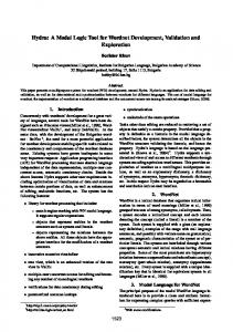
79.9m, Beam is 22m, Draft is 3.5m, the maximum speed is ~ 50 knots, and the range is ~ 4000 nautical miles. Two sets of tests were performed using the 1/15 scale Sea Fighter model: (1) motion and slamming test for motion and slamming loads validation and (2) fix yaw towing test for hull lifting force prediction. The motion and wetdeck slamming model tests were carried out at NSWCCD in October 2006. The Sea Fighter model was tested in regular head waves. Both fixed and 2-degree-of-freedom (DOF) tests were carried out. These tests provided the following data: kinematics for 2-DOF tests, pitch motion, heave motion, bow acceleration for 2-DOF tests, total body force for fixed tests, vertical force measured at the CG, pitch moment about the CG, and wetdeck slamming incidence and slamming pressures for both sets. A snap shot of the Sea Fighter encountering wetdeck slamming during the test is shown in Fig. 4.
Fig. 5:
Fig. 6:
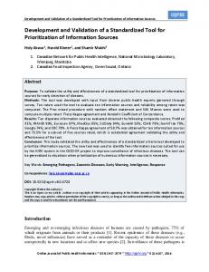
Time History of Measured Wetdeck Slamming Pressure at Pressure Panels at Spot 149
Sea Fighter Slam Pressure Panel Placement
In addition to motions and wetdeck slamming, the model was also towed at fixed yaw angles to quantify the lifting forces and moments generated by the two hulls. These quantities are important to ship maneuvering predictions. More detail of this Sea Fighter model test is given in Lin et al. (2007).
Validation of Prediction Capabilities Fig. 4:
Sea Fighter Wetdeck Slamming
Results for four test conditions were analyzed carefully. Table 3 summarizes these four cases, referred to as “Spots”. Note that two cases were free to heave and pitch, and two were fixed. As indicated in the table, wetdeck slamming was observed in Spots 149 and 206. Table 3:
Experimental Cases Provided by DSWCCD
Parameter Model Speed, kts Froude No. Dipl. LT Draft, ft Wave ht., ft Lwave/Lship Slams
Spot 149 Free 15.6 0.301 1377 11.96 8.8 1.6 Yes
Spot 152 Free 25.9 0.498 1377 11.96 7.5 1 No
Spot 206 Fixed 15.6 0.301 2079 16.31 7.5 1 Yes
Spot 211 Fixed 8.9 0.172 2079 16.31 7.5 1 No
Sample time histories of measured wetdeck slamming pressure (equivalent full scale, psi) at pressure panels are shown in Fig. 5. The placement of the pressure panel under the wetdeck is shown in Fig. 6.
Extensive validation of the prediction tools was done using the HSSL model test data and the Sea Fighter test data. A limited set of results are presented in this paper. Ship Resistance Das Boot resistance predictions have not yet been made for the model test hullform, which is somewhat heavier than the optimized design. However, existing Das Boot predictions for the optimized design have been scaled to estimate the model hullform resistance by applying a surrogate drag model that was specifically developed for the HSSL design. It is based on a series of predictions for scaled versions of the optimum that include displacement variation, so it is expected to be quite accurate for this purpose. A comparison of tank data with Das Boot results that have been scaled in this manner is shown in Fig. 7 for the high-speed catamaran mode of operation. The predicted and measured resistance is very well correlated. Overall, the Das Boot predictions and SHAPE optimization appear to have worked excellently for this design configuration.
pressure in the model test was obtained by converting a strain gauge measurement on the slam panel. As a result, the slamming pressure could appear to be negative after a slam event from structural vibration of the slam panel.
Full Scale Resistance - lbf Millions
3.0 Model Test Das Boot
2.5 2.0 1.5 1.0
Full Scale LCG: 261.8 ft forward of transom Full Scale Displacement: 19,320 LT
0.5 0.0 15
20
25
30
35
40
45
50
55
Full Scale Speed - kts
Fig. 7:
Wave Resistance Comparison
Ship Motions and Slamming Loads For both the Sea Fighter and HSSL hullform motion tests, the experimental wave time history was recorded by a wave probe. Fourier decomposition was used to reconstruct the experimental wave through a summation of sinusoidal wave components that could be input into the LAMP code, allowing LAMP to simulate the motion of the model for each tank pass on a wave-by-wave basis. For the Sea Fighter hullform, sample comparison of the heave and pitch motions at Spot 149 are plotted in Figs. 8 and 9, showing that LAMP captures the phasing and magnitude of the ship motion correctly.
Fig. 10:
Vertical Acceleration Comparison at Spot 149
0.15 Experiment
LAMP
0.1
Heave, m
0.05 0 -0.05 -0.1
Fig. 11:
-0.15 0
5
10
15
Time, s
Fig. 8:
Heave Motion Comparison for Spot 149 Spot 149 Pitch
8 Experiment
LAMP
6
Pitch, deg
4 2 0
23
-2 -4 -6 -8 0
5
10
15
Time, s
Fig. 9:
Pitch Motion Comparison for Spot 149
Figs. 10 and 11 compare vertical acceleration near the bow and slamming pressure at Spot 149 for a run in which the Sea Fighter hullform was free to pitch and heave. Slamming pressures in the LAMP model are captured by coupling a semi-empirical wedge entry model to the motions and incident wave boundary conditions determined by the LAMP simulation. A slamming model based on the model proposed by Ge, Faltinsen, and Moan (2005) was used, and the forces resulting from such slamming pressures were then added to the motion of the vessel. As can be seen, LAMP captures the overall magnitude and phasing of both responses quite well. It should be noted that the
Pressure Comparison at Spot 149
A similar series of comparison were carried out with the HSSL hullform in both regular and irregular waves. Again, generally good agreement was observed between the LAMP predictions and experimental results. It was clear from the experimental results that significant viscous damping and spray formation took place during high-speed runs when the step in the hull between catamaran and SWATH modes was placed near the still waterline. In these cases, LAMP tended to give higher motion predictions than the model test results. A sample comparison for pitch displacement in a simulated sea state 5 (significant wave height Hs=3.26m and modal period Tp=9.7sec) at 43 knots forward speed is shown in Fig. 12. More detailed results are summarized in Lin and Collette (2007).
Fig. 12:
Pitch Motions Comparison for HSSL Hullform
SES Motions in Head Seas The initial LAMP SES model was also compared to the motions of the HSSL hullform tested in SWATH mode with the SES cushion deployed. The initial SES model in LAMP featured the effect of the cushion pressure on the free surface boundary condition and the hull. Leakage was modeled by constant-gap seal elements; an air supply was modeled with a linearized fan curve relating delivered air to cushion pressure. The pressure in the cushion was determined by an adiabatic ideal gas law, accounting for the changing cushion volume in waves, leakage of air from seals, and air supplied from the fans. In general, this simple SES model agreed quite well with experimental results at low speeds. Sample pitch motion results for zero speed in sea state 5 (Hs=3.26m and Tp=9.7sec), with the cushion supporting 24% of the vessel’s weight, is shown in Fig. 13. At higher speeds, the constant-gap seal expression starts to break down, and the simple SES model will overpredict the SES motions.
Fig. 15:
Stable Spiral Maneuver with Skeg
A further comparison of turning circles at 20 knots full scale (Froude Number 0.385) was made between the LAMP results and the experimental data for the Sea Fighter hullform. As can be seen from the data in Table 4, the experimental results and LAMP results are in reasonable agreement. Table 4:
Comparison of Turning Circle Results
Fin Type Fin C Fin D Fin E
Experimental (ship lengths) 5.5 3.7 3.6
LAMP-3 (ship lengths) 5.8 4.3 3.9
Yaw Test
Fig. 13:
SES Pitch Motions for HSSL Hullform
Ship Maneuvering in Calm Water When dealing with unconventional hullforms, a numerical method for evaluating the maneuvering characteristics of the hullform is advantageous. The maneuvering characteristics predicted by the hybrid maneuvering model in LAMP (Lin et al., 2006) were compared to existing manuevering model test results for the Sea Fighter hullform. A key test was to determine if the LAMP approach would correctly indicate that the bare hull was unstable, while the addition of a skeg made the hull stable. This was investigated by comparing the spiral maneuvers for the bare hull and hull with skeg. As can be seen from Figs. 14 and 15, the LAMP maneuvering approach was able to identify the unstable spiral tests that do not pass through the origin (Fig. 14) from the stable tests that do (Fig. 15).
In maneuvering simulations, lifting forces and moments generated by the body are required. However, potential flow codes such as LAMP cannot capture the lifting forces and moments properly; in the LAMP maneuvering approach, these forces must be determined by other means and included in the calculation as an additional force model (Lin et al., 2006). One approach to this problem is to use a viscous flow code to compute the hull lifting forces and moments. A surrogate model can be built based on the viscous flow computation results for use in the LAMP simulations. In the HSSL program, the viscous flow tool FANS was evaluated as a potential tool to build a surrogate maneuvering model. The Sea Fighter hullform was towed down the tank at several fixed yaw angles, and the total side force and moment on the hull was recorded. These experiments were simulated in the viscous flow code FANS, and the results were compared to the experimental values. Table 5 compares side forces, with excellent agreement between the codes and the experiments. Initial comparisons of the resulting moment were not as favorable; the experimental wave profile and FANS results are currently being compared in order to explain the difference. Table 5:
Yaw Angle 2° 4° 6° Fig. 14:
Unstable Spiral Maneuver for Bare Hull
Side Force Comparison between FANS and Experimental Data, 20 Knots Full Scale (Fn=0.385)
Experimental Side Force (lbf) 43.38 90.97 127.08
FANS Side Force (lbf) 41.98 88.18 128.11
Conclusions The SAIC-led HSSL effort has extended and evaluated a set of software tools for the hydrodynamic design and performance assessment of innovative high-speed sealift hullforms. The current effort evaluated tools for resistance, motions, slamming loads, SES systems, and maneuvering. Using a series of model tests, these tools were assessed for their ability to provide useful guidance to designers. Non-linear potential flow codes such as Das Boot and LAMP have shown the ability to capture resistance and overall motions effects of innovative hullforms. Additionally, extending such potential flow codes with additional models has allowed a wide range of practical design problems to be tackled, including estimations of slamming pressures, modeling motions with active SES cushions, and investigating maneuvering. While viscous flow codes can be used for limited analysis of motions and loads on their own at this point, viscous flow predictions have proven useful in providing data for extensions models for potential flow code.
Acknowledgements The authors would like to thank Dr. L. Patrick Purtell of ONR for his support of the HSSL program, and to thank the staff in the HPC office at ONR and at ARL who assisted with access and support for the JVN cluster. The authors would also like to thank the following team members of the SAIC-led HSSL team for their outstanding contribution to the overall HSSL program effort: Kenneth Weems, Sheguang Zhang, Daniel Liut, Michael Meinhold, Kristine Chevalier, Don Wyatt, and Tin-Guen Yen of SAIC; Greg Buley Volker Stammnitz and Chris Clayson of CDIM-SDD; Yuming Liu and Hongmei Yan of the Massachusetts Institute of Technology; Allen Engle, Ann Marie Powers, and Bryson Metcalf of NSWCCD; Gene Miller and Dave Helgerson of Computer Science Corporation; Ham-Chin Chen of Texas A&M University; Han Yu of the American Bureau of Shipping; and Gary Shimozono of Navatek.
References Chen, HC, and Yu, K (2006). “Numerical Simulation of Wave Runup and Greenwater, on Offshore Structures by a Level-Set RANS Method,” Proceedings of the 16th International Offshore and Polar Engineering Conference, San Francisco, California. Faltinsen, OM, and Zhao, R (1991). “Numerical Predictions of Ship Motions at High Forward Speed,” Phil. Trans. R. Society of London, A. Vol. 334, pp. 241-252. Ge, C, Faltinsen, O., and Moan, T. (2005), “Global Hydroelastic Response of Catamarans Due to Wetdeck Slamming”, Journal of Ship Research, Vol. 49, No. 1, pp 24-42.
Kuhn, JC, Chevalier, KL, Schlageter, EC, Scragg, CA, and Wyatt, DC (2007). “The Use of Linear Programming and Basis Functions for Hull Form Optimization,” Proceedings of the 9th International Conference on Numerical Ship Hydrodynamics, Ann Arbor, Michigan. Lin, WM, and Yue, DKP (1990). “Numerical Solutions for Large–Amplitude Ship Motions in the Time Domain,” Proceedings of the Eighteenth Symposium on Naval Hydrodynamics, The University of Michigan, Ann Arbor, Michigan. Lin, WM, and Yue, DKP (1993). “Time-Domain Analysis for Floating Bodies in Mild-Slope Waves of Large Amplitude,” Proceedings of the Eighth International Workshop on Water Waves and Floating Bodies, St. John’s, Newfoundland, Canada. Lin, WM, Zhang, S, Weems, KM, and Yue, DKP (1999). “A Mixed Source Formulation for Nonlinear Ship-Motion and Wave-Load Simulations,” Proceedings of the 7th International Conference on Numerical Ship Hydrodynamics, Nantes, France. Lin, WM, Zhang, S, Weems, KM, and Liut, DA (2006). “Numerical Simulations of Ship Maneuvering in Waves,” Proceedings of the 26th Symposium on Naval Hydrodynamics, Rome, Italy. Lin, WM, and Collette, M (2007). “LAMP Validation and Modeling Recommendations – ONR HSSL Model Test Program,” SAIC Report # ASTD 08003. Lin, WM, Zhang, S, Weems, KM, Jones, P, Meinhold, M, Bryson M, and Powers, A (2007). “Numerical Simulation and Validation Study of Wetdeck Slamming on High-Speed Catamaran,” Proceedings of the 9th International Conference on Numerical Ship Hydrodynamics, Ann Arbor, Michigan. Liut, DA, Weems, KM, and Lin, WM (2002). “Nonlinear Green Water Effects on Ship Motions and Structural Loads,” Proceedings of the 24th Symposium on Naval Hydrodynamics, Fukuoka, Japan. Pontaza, JP, Chen, HC, and Reddy, JN (2005). “A localanalytic-based discretization procedure for the numerical solution of incompressible flows.” International Journal for Numerical Methods in Fluids, Vol. 49, No. 6, pp. 657-699. Salvesen, N, Tuck, EO, and Faltinsen, O (1970). “Ship Motions and Sea Loads,” Transactions of the Society of Naval Architects and Marine Engineers, Vol. 78, pp. 250-287. Shin, YS, Belenky, V, Lin, WM, Weems, KM, and Engle, AH (2003). “Nonlinear Time Domain Simulation Technology for Seakeeping and WaveLoad Analysis for Modern Ship Design,” Transactions of the Society of Naval Architects and Marine Engineers. Shin, YS, Belenky, VL, Paulling, JR, Weems, KM, and Lin, WM (2004). “Criteria for Parametric Roll of Large Containerships in Longitudinal Seas,” Transactions of the Society of Naval Architects and Marine Engineers.
Wyatt, DC (2000). “Development and Assessment of a Nonlinear Wave Prediction Methodology for Surface Vessels,” Journal of Ship Research, Vol. 44, No. 2, pp. 96-107. Zhang, S, Liut, DA, Weems, KM, and Lin, WM (2005). “A 3-D Finite Volume Method for Green Water Calculations,” Proceedings of the 24th International Conference on Offshore Mechanics and Arctic Engineering (OMAE2005), Halkidiki, Greece.
Zhang, S Weems, KM, and Lin, WM (2007), “Numerical Simulations of Ship-Ship Interactions,” Proceedings of the 9th International Conference on Numerical Ship Hydrodynamics, Ann Arbor, Michigan.