POWER-GEN 2003, 9-11 December
RECENT PROGRESS IN PREDICTING, MONITORING AND CONTROLLING COMBUSTION DRIVEN OSCILLATIONS IN GAS TURBINES Tim Lieuwen, Assistant Professor School of Aerospace Engineering, Georgia Institute of Technology Atlanta, GA 30332-0150 Ph. 404-894-3041, Email:
[email protected] Geo. Richards, Focus Area Leader, Energy System Dynamics National Energy Technology Laboratory U.S. Department of Energy Morgantown, WV 26505 Ph. 304-285-4458, Email
[email protected] The objective of this paper is to provide readers with an understanding of recent improvements in methods for monitoring, understanding, and controlling combustion driven oscillations, often referred to as “humming”. These oscillations continue to present one of the key problems associated with the design and operation of DLN combustion systems. They are detrimental to turbine performance and health and are manifested by oscillations in pressure, rate of heat release, and flow rate. These oscillations, and their resultant structural vibrations, cause fretting and wearing at part interfaces, flame flashback or blowoff, enhanced heat transfer to liners and overall performance degradation.
Background Combustion oscillations have become an issue of increasing prevalence as emissions targets are lowered. These low emissions levels are achieved by reducing the flame temperature in the combustor by premixing the fuel and air prior to combustion with large amounts of excess air. Since NOX is produced at high temperature, this methodology is able to reduce NOX. However, these lower temperatures also cause the CO intermediaries to take longer to oxidize to CO2. As such, relatively large combustion systems are needed to allow sufficient time for the reaction to complete. As opposed to conventional diffusion flame combustors or aero engines, very little cooling air is permitted to enter the combustion zone. Additional cooling air freezes the combustion reaction resulting in elevated levels of CO. Elimination of these cooling holes eliminates a substantial source of acoustic damping and likely plays a key role in the propensity of low emission combustors to acoustic oscillations. These oscillations are driven by fluctuations in the rate of heat release by the flame. Nominally, the rate of heat release in a combustor has some small inherent unsteadiness due to the turbulent flow oscillations. Under certain conditions, however, the heat release couples to the natural acoustic modes of the combustion chamber in a self-exciting manner. The resultant oscillations often occur at discrete frequencies that are associated with the natural frequencies of the combustion chamber
1
POWER-GEN 2003, 9-11 December
Combustion instabilities are not a new problem. Glassblowers have known for centuries of the spontaneous oscillations that can be generated by heating the end of a glass tube. Numerous high profile rocket systems such as the Saturn rockets (which put the first man on the moon), the Minuteman intercontinental ballistic missile, Air-to-air Sidewinder missiles, space shuttle solid rocket booster, or Mars Pathfinder descent motor have had instability problems. In addition, they have and continue to cause problems in industrial furnaces, gas turbine engines for military and civilian applications, and afterburners. However, the problems that combustion driven oscillations cause in land based systems are distinct. In a rocket, some level of oscillation is tolerable as long as it doesn’t vibrate the system so violently as to render the control system ineffective or physically destroy the engine within the time required to complete the mission. Thus, the few psi oscillations that occur in the space shuttle solid rocket boosters is acceptable, while the several hundred psi oscillations that have appeared in other rockets is not. In contrast, gas turbine oscillations are quite small in amplitude relative to those observed in rockets or ramjets. However, the need to operate these systems for many thousands of hours without maintenance or overhaul implies that these relatively small amplitudes are still unacceptable in level. The rest of this paper summarizes recent progress and challenges associated with predicting the frequencies and amplitude of dynamics, measuring their characteristics, and eliminating them when they occur
Dynamics Prediction Capabilities The dynamics of an unstable combustor are controlled by a complex interplay of linear and nonlinear processes. From a combustor designer’s point of view, three basic characteristics must be predicted - frequency, conditions of occurrence, and amplitude of the oscillations. These are listed in order of increasing prediction difficulty. Linear combustor processes generally control the balance between driving and damping processes at low amplitudes of oscillation and, thus, determine the frequency and conditions under which inherent disturbances in the combustor grow or decay. Capabilities for modeling the acoustics of the combustor system are reasonably well developed1. As such, characteristics such as natural frequencies of oscillation and acoustic mode shapes can be predicted with good accuracy, often with little model calibration or tuning. Generally, accurate predictions simply require knowledge of the geometric characteristics of the system and average temperature distributions. Predicting the conditions under which instabilities will actually occur requires an understanding of the interactions of flow and mixture disturbances with flames. This is substantially more complicated than simply predicting acoustic mode shapes, and as such, these capabilities are less well developed but are improving rapidly. In particular, improved understanding of the mechanisms responsible for these oscillations is has improved, providing modelers with some focus as to which key physical processes must be most carefully accounted for. A particularly important mechanism arises from oscillations in the fuel/air ratio of the reactive mixture. Analysis of this mechanism shows that it is self-exciting when the product of the frequency of oscillation and the delay between the time a fuel parcel is injected into the premixer and burned at the flame equals a certain range of values. Thus, it is known that premixer characteristics have a
2
POWER-GEN 2003, 9-11 December
significant impact on the combustor’s stability. Much of this work is being transitioned to industry and being incorporated into dynamics predictions codes. In fact, most gas turbine manufacturers have reported some efforts to develop models to predict instability frequencies, mode shapes, and conditions of occurrence,2,3,4. Understanding of a combustor’s linear dynamics is not sufficient to describe the finite amplitude dynamics of self-excited oscillations; e.g., for predicting the instability amplitude. Such capabilities require consideration of the response of flame’s to large amplitude to disturbances, a topic which is not well understood even in simple laboratory flames. As such, dynamics amplitude prediction capabilities are currently in their infancy.
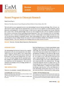
Monitoring Combustion Dynamics Even simple measurements of the dynamic combustor characteristics is a challenge due to the extreme combustor environment. Recently, methods and new instrumentation concepts for measuring these oscillations have improved. First, a variety of new high temperature dynamic pressure sensors have come on the market. Some manufacturers claim that these devices are appropriate for flush mounting in high temperature environments (i.e., they do not require stand off tubes) and capable of withstanding continued operation at temperatures in excess of 1000 F. In the authors’ opinion, users of this instrumentation should exercise some caution in these claims and periodically re-check the sensitivity of these devices. The reason for this is that most transducers use piezoelectric crystals whose Curie temperature represents the temperature above which the material loses its piezoelectric properties. Even at temperatures below, but sufficiently close to the Curie value, the material may slowly de-polarize. If this were to occur, this would manifest itself as a perceived reduction in the dynamics amplitude, even if the amplitude were in fact not changing! In cases where the transducer must be thermally isolated, stand-off tube designs have been shown to be a flexible and convenient way to accurately measure the dynamic pressure, without requiring high temperature transducers. Use of such tubes requires a thorough understanding of their acoustics as temperature gradients, slight area changes, and viscous dissipation can cause appreciable variation in the tube transfer function over the frequency range of interest. Such calibrated devices are commercially marketed; e.g., by Power Systems Manufacturing. The reader should be aware, however, that naïve use of uncalibrated systems, such as mounting a pressure transducer on a long coil, can give highly erroneous results. In addition, flame chemiluminescence sensors, such as the ultra-violet detectors routinely used to detect flame light-off can be used to monitor dynamics. Such devices are routinely used in laboratory environments, but do not appear to be used in practical devices. Characterization of these optical emissions are an excellent way of characterizing the unsteady heat release that is driving the pressure oscillations. Finally, a novel electrostatic probe that is integrated with the fuel nozzle has also been shown to be a useful way for characterizing dynamics. This device was developed at the National Energy Technology Lab and is currently being commercialized by Woodward Industrial Controls. A sketch of this device is shown in Figure 1. The probe operates by recording the electrical conductivity of the flame as measured from two electrodes built into the fuel injector. Because the conductivity of the flame is related to
3
POWER-GEN 2003, 9-11 December
the fuel-air ratio, the electrode close to the flame can record a signal that is related to the overall fuel-air ratio. The adjacent electrode can detect the transient passage of the flame into the premix passage during combustion dynamics, and provides a useful signal for detecting both dynamics and unwanted flame flashback. More details can be found in reference [5]. Swirl Vanes
Fuel Nozzle
Combustion Chamber
Isolated Flashback Electrodes
Fuel & Air Flow From Premixer
Electrically Isolating Material Nozzle Center-Body
Figure 1 Sketch of the electrostatic sensor used to measure combustion conditions, and combustion dynamics, from reference [5].
Controlling Combustion Dynamics Various methods for passively controlling these oscillations have been developed. Symmetry breaking measures are routinely used to eliminate humming. For example, some degree of non-uniformity to fuel splits from one nozzle to the next is used intentionally to create asymmetries in the response of the flame to oscillations. In many instances, this asymmetry is produce by piloting a portion of the main premixed flame, so that the dynamics of the flame can be controlled by adjusting the pilot level. The pilot flame may be a diffusion flame, or partly premixed. Because diffusion flames have greater dynamic stability than premixed ones, this approach has the advantage that the stability can often be improved simply by increasing the pilot level. However, the diffusion pilot flame produces significant NOx, so the level of pilot fuel must be traded against emissions performance. The installed stability margin of production engines depends critically on details of the combustor and fuel injector manufacturing tolerances, as well as the site-specific fuel composition. For this reason, it is typical that engine commissioning requires adjustment of the flow splits associated with various load ranges; e.g., see Ref. [6]. The flow split settings may likewise require updating as the combustion liner seals wear, or to accommodate seasonal changes in natural gas composition or ambient conditions. In another approach to symmetry-breaking, OEM’s have developed various devices to alter the convective delay time required for fuel to convect to the flame by welding on cylindrical burner nozzle extensions or varying the premixer characteristics. This technique has been shown to be successful at extending the useful power range of engines that were otherwise limited by combustion dynamics7. A practical consideration for this technique is that it increases the number of unique engine components (i.e., parts count) and may therefore complicate overhaul procedures. The improved stability would seem to outweigh these modest complications.
4
POWER-GEN 2003, 9-11 December
Another highly promising technique adjusts the acoustic properties of the fuel supply system, similar to successful approaches used in liquid rocket engines. The basic idea behind this approach is to tune the fuel line acoustics to deliver fuel pulses that are out of phase with the oscillations, thereby preventing their occurrence. The fuel supply characteristics can be modified through a number of means, such as by adding side branches, volumes, or resonators, changing the fuel line length, altering the fuel injector impedance, etc. Successful laboratory scale tests of this technique have been reported in References [8] and [9]. Figure 2 compares the oscillating pressure from a baseline and optimally tuned combustor9. The horizontal axis are the fuel/air ratio, and the bulk premixer velocity. The vertical axis is the amplitude of the observed pressure oscillation. Comparing the two figures, a significant improvement in the stability can be achieved by fuel system tuning. This concept is being developed for tests on larger scale combustors by the National Energy Technology Laboratory.
2 RMS (kPa)
Baseline
1 0
0.9 1
5
1
0.6
8
2
0 2
3
2
5
2
8
3
0
Controlled
2 RMS (kPa)
1 0.9 0.6
30
Velocity (m/s)
25
20
15
0
Figure 2. Comparison of a the oscillating pressure amplitude (RMS) at various operating conditions using a baseline combustor (top) and with an optimally tuned fuel system (bottom), From reference [9].
In addition, external damping devices have been demonstrated, such as “1/4 wave tubes” or Helmholtz resonators. The basic characteristics of these devices are well understood, although it appears they are not often implemented during the design stage, but as an after-the-fact fix. A commercial example of resonator use is on the LM series of aeroderivative engine6. Finally, active control of instabilities continues to be a candidate technology for eliminating dynamics in an unstable machine. The basic idea behind such a system is to
5
POWER-GEN 2003, 9-11 December
have a secondary fuel injector that modulates a fuel stream out of phase with the oscillations. Such approaches have been extensively validated in laboratory tests, and actually fielded and demonstrated in a full scale system by Siemens-Westinghouse. However, there is a widespread reluctance on the part of OEM’s to implement these systems, due to their additional complexity, cost, and reliability concerns.
References 1 Munjal, M., Acoustics of ducts and mufflers, John Wiley: New York, 1987. 2 Kruger, Uwe et al., ASME Paper #99-GT-111, 1999. 3 Walz, G. et al, ASME Paper #99-GT-113. 4 Schuermans, B. et al, ASME Paper #99-GT-132. 5 Benson, K. Thornton, J. D., Straub, D. L., Huckaby, E. D., Richards, G. A. (2003). “Flame Ionization Sensor Integrated into a Gas Turbine Fuel Nozzle,” ASME Paper #GT2003- 38470 6 Pandalai, R. P., and Mongia, H. C., "Combustion Instability Characteristics of Industrial Engine Dry Low Emission Combustion Systems," AIAA 98-3379, 1998. 7 Berenbrink, P., and Hoffmann, S. "Suppression of Dynamics Combustion Instabilities by Passive and Active Means," ASME 2000-GT-0079, 2000. 8 : Lee, J. G., Kim, K., Santavicca, D. A., “A Study of the Role of Equivalence Ratio Fluctuations During Unstable Combustion in a Lean Premixed Combustor,” AIAA 2002-4015, 2002. 9 Richards, G. A., Straub, D. L., Robey, E. H. ”Control of Combustion Dynamics Using Fuel System Impedance,” ASME GT-2003-38521, 2003.
6