RADIOENGINEERING, VOL. 25, NO. 2, JUNE 2016
275
Reconfigurable Plasma Antenna Array by Using Fluorescent Tube for Wi-Fi Application Hajar JA’AFAR1, Mohd Tarmizi ALI 2, Ahmad Nazri DAGANG3, Idnin Pasya IBRAHIM2, Nur Aina HALILI2, Hanisah MOHD ZALI2 1
Faculty of Electrical Engineering, Universiti Teknologi MARA (Terengganu), Sura Hujung 23000 Dungun, Malaysia 2 Faculty of Electrical Engineering, Universiti Teknologi MARA (UiTM), 40450 Shah Alam, Selangor, Malaysia 3 School of Ocean Engineering, Universiti Malaysia Terengganu, 21030 Kuala Terengganu, Terengganu, Malaysia
[email protected] Manuscript received March 19, 2016
Abstract. This paper presents a new design of reconfigurable plasma antenna array using commercial fluorescent tube. A round shape reconfigurable plasma antenna array is proposed to collimate beam radiated by an omnidirectional antenna (monopole antenna) operating at 2.4 GHz in particular direction. The antenna design consists of a monopole antenna located at the center of a circular aluminum ground. The monopole antenna is surrounded by a cylindrical shell of conducting plasma. The plasma shield consists of 12 commercial fluorescent tubes aligned in series containing a mixture of argon gas and mercury vapor which upon electrification forms plasma columns. The plasma behaves as a conductor and acts as a reflector in radiation, in the condition where plasma frequency, ωp is higher than the operating frequency. From this concepts, when all plasma elements are activated or switched to ON, the radiation signal from the monopole antenna will trapped inside the plasma blanket and meanwhile when one or more plasma elements is deactivated (switched OFF), the radiation from the monopole antenna will escape. This antenna has the capability to change its patterns with beam direction at 0°, 30°, 60°, 90°, 120°, 150°, 180°, 210°, 240°, 270°, 300° and 330° at frequency 2.4 GHz. The proposed antenna has been successfully fabricated and measured with conclusive results.
Keywords Plasma elements, reconfigurable radiation pattern, monopole antenna
1. Introduction The term plasma is often referred to as the fourth state of matter. As the temperature increases, molecules become more energetic and transform in the sequence solid to liquid to gas and plasma. Plasma is a collection of ionized positive ions and free moving electrons; usually the ionization degree is very low, less than 1% [1]. Plasma can be
DOI: 10.13164/re.2016.0275
generated by UV laser irradiation, or by laser initiated preionization followed by high voltage break down to form the main conducting channel or by simply using commercial fluorescence tube to serve as reflector, or by much more expensive electron beam [2]. There were also exotic methods like explosion generating plasma antenna for fusion research. The plasma will be present when electron and nucleus that form the atom is no longer able to stay together due to high kinetic energy. It happens due to the electrons are stripped out from the atoms. Plasmas are conductive, and respond to electric and magnetic fields, moreover it also can be an efficient source of radiation. If the sustaining energy is insufficient, plasma will turn into gas form. Plasma Antenna is a general term which represents the use of ionized gas as a conducting medium instead of metal to either transmit or reflect a signal to achieve radar or stealth or other communication purpose. A plasma antenna is a radio frequency (RF) antenna based on plasma elements instead of metal conductors [3–5]. Such antennas are constructed from insulating tubes filled with low pressure gases. Recently there has been interest in the use of plasmas as the conductor for antennas, as opposed to the use of metals. Plasma can be rapidly created and destroyed by applying electrical pulse to the discharge tube. Hence plasma antenna can be rapidly switched on and off [6]. When it is off it is non-conducting and invisible to electromagnetic radiations. When it is on, plasma is a good conductor. Plasma is highly conducting and acts as a reflector for radiation for frequencies below the plasma frequency. Because of its unique properties plasma antenna can be as a radiation pattern reconfigurable antenna. Reconfigurable antennas possess very attractive features such as the ability to reconfigure themselves autonomously, to adapt to changes or with the system to perform entirely different functions. The reconfigurable antenna is also capable of providing a single antenna for the use with multiple systems. Most of reconfigurable antennas are constructed by using metallic elements along with active devices. These
APPLICATIONS OF WIRELESS COMMUNICATIONS
276
H. JA’AFAR, M. T. ALI, A. N. DAGANG, ET AL., RECONFIGURABLE PLASMA ANTENNA ARRAY BY USING FLUORESCENT ...
active devices were employed to provide switching mechanism for the antennas in order to steer beam in particular directions. In the area of communication, the plasma element was considered as an effective radiator to release the electromagnetic energy just as the metal element did. Hence, in the present paper the main objective is to design and develop reconfigurable plasma antenna array using fluorescent tube for Wi-Fi application at frequency 2.4 GHz. This paper will also discuss and explain the concept of using plasma elements as reconfigurable antennas rather than using metallic antenna. The new concepts of reconfigurable and beam steering were implemented to design this antenna by using plasma element instead of metal element. The special properties of plasma which can be rapidly activated (switch ON) and de-activated (switch OFF) in few second can be advantage to design and develop reconfigurable radiation pattern antenna. Implementation of reconfigurable plasma antenna array on a single ground plane enables the radiation pattern to reconfigure over 12 directions to be realized just at fingertips. The reconfigurable plasma antenna array is a reconfigurable antenna using a combination of monopole antenna and fluorescent tube function as a plasma medium to produce beam steering control. In contrast to conventional antennas producing fixed directional radiation patterns, the reconfigurable plasma antenna array structure is capable of scanning the beam pattern over 360°. Simulated and measured results of tests on the three antennas are presented and compared to demonstrate the performance of the proposed antennas. These results confirmed that the main beam directions can be pointed to the desired direction by controlling the switched ON and switched OFF of the fluorescent tube. In this work, the simulation is performed by using the simulation software Computer Simulation Technology (CST) Microwave Studio. This paper is structured as follows: Section 2 describes the antenna design and structure, Section 3 is focused on the analysis of reconfigurable plasma antenna array, in Sec. 4 results and discussion are given, and finally Section 5 is conclusion.
2. Antenna Design and Structure There are several equations and parameters that need to be considered to design this antenna, especially the behavior of the plasma. To simulate the performance of this antenna, CST MWS software based on finite integral technique is used. The behavior of the plasma is given by Drude dispersion model. The Drude dispersion model describes simple characteristics of an electrically conducting collective of free positive and negative charge carriers, where thermic movement of electron is neglected. There are two parameters that need to be considered to design by using plasma element: the first one is plasma frequency and the second is collision frequency. Plasma frequency is a natural frequency of the plasma and is
a measure of the amount of ionization in plasma. One must distinguish the difference between the plasma frequency and the operating frequency of the plasma antenna. The plasma frequency is a measure of the amount of ionization in the plasma while the operating frequency of the plasma antenna is the same as the operating frequency of a metal antenna. While for collision frequency, in weakly ionized plasmas, the (charged) plasma particles collide mostly with neutral atoms and molecules. The equation for plasma frequency is shows in (1) and collision frequency in (2).
p
e 2 ne 0me
(1)
where ne is the electron density [m-3], e is the electron charge [C], me is the electron mass [kg] and ε0 is the free space permittivity [F/m]. From
vc ne av
(2)
where νc [1/s] is collision frequency, a is collision cross section and v is electron speed. The electron densities are obtained from the numerical calculation of Glomac software [7]. From Glomac, the electron density ne for each fluorescent tube is equal to 1.13 × 10¹⁸ m-3. In order the plasma element to act as a metal, the ωp must be higher than the operating frequency. When ωp is larger enough than the operating frequency, the plasma exhibits good electrical conductivity σ as given in (3).
ne q 2 . mvc
(3)
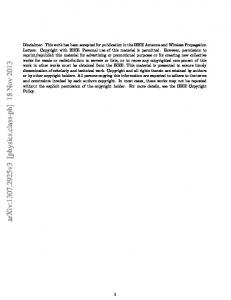
The structure of the proposed antenna is shown in Fig. 1(a), (b) and (c). The reconfigurable plasma antenna array structure consists of 12 tubes of commercial cylindrical shaped fluorescent tubes that contain the mixture of mercury vapor and argon gas. The ground is circular aluminum plate with thickness of 3 mm and radius of 105 mm. The height of each plasma tube from ground plane surface, LPA is 288 mm and its diameter is 16 mm. The energy source is supplied by a monopole antenna resonating at 2.4 GHz and located at the center of the ground plane. The height of monopole antenna is 35 mm with diameter of 3 mm. The antenna is fed by a standard SMA connector that is located at the middle of the ground. The probe feed (coaxial feed) is a technique that is used in this project for feeding microstrip patch antennas and fed by a SMA connector. SMA connector design is according to specification in using Teflon with dielectric constant of 2.08. The impedance of feeding coaxial transmission line is 50 Ω. The tubes used in the simulation are made from lossy glass pyrex with permittivity of 4.82. The tube wall (glass) has a thickness, t = 0.1 mm. The distance between the monopole antenna to fluorescent tubes, DBB is equal to 70 mm. The angle between the centers of two adjacent elements is 30º. The optimized parameters of reconfigurable plasma antenna array are presented in Tab. 1.
RADIOENGINEERING, VOL. 25, NO. 2, JUNE 2016
(a)
277
monopole antenna to the fluorescent tube are varied from 50 mm until 80 mm with increment 10 mm. As depicted in Fig. 2(a), it clearly shows that the distance between the monopole antenna to the fluorescent tube, DBB has a significant effect on return loss and resonant frequency. With DBB = 50 mm, the resonant frequency is 1.79 GHz and S11 = –14.04 dB but when DBB is 60 mm, two resonant frequencies fall, the first one at 1.71 GHz (S11 = –19.99 dB) and the second one at 2.84 GHz (S11=–11.79 dB). When DBB becomes 80 mm the S11 is –12.49 dB at frequency 2.18 GHz. So from analysis, the optimum result for the antenna to operate at frequency 2.4 GHz is when DEE = 70 mm.
(b)
As depicted in Fig. 1(b), the structure of the reconfigurable plasma antenna array contains an aluminum ground.
(c)
(d)
(e)
Fig. 1. Geometry of the reconfigurable plasma antenna array: (a) top view, (b) side view, (c) overall structure, (d) photograph of the fabricated antenna prototype, (e) 5/12 plasma switched to ON. Label
Dimension (mm)
Space gap between plasma elements
DAA
36
Distance between plasma element to monopole antenna
DBB
70
Aluminum ground plane radius
DCC
105
Parameter
Aluminum ground plane thickness
t
3
Length of plasma element
LPA
288
Diameter of plasma element
DPA
16
Length of monopole antenna
LM
35
Diameter of monopole antenna
DM
3
θ
30°
Angle between two adjacent plasma elements Tab. 1. Optimized reconfigurable specifications.
(a)
(b) plasma
antenna
array
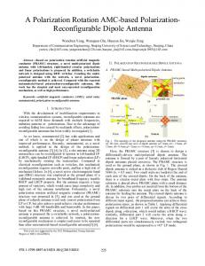
3. Analysis of Reconfigurable Plasma Antenna Array In this section, the analysis of parametric study is presented to ensure that the effects were taken place at the desired frequency mode. The target frequency bands is 2.4 GHz. The simulation is performed by using the commercially available simulation software CST Microwave. Figure 2(a)–(c) shows the simulated parametric studies on the reflection coefficient S11, when some parameters are varied. Figure 2(a) shows the simulated results on the reflection coefficient S11 when the distance between the
(c) Fig. 2. Effect of (a) the distance between the monopole antenna to the fluorescent tube DBB, (b) the ground thickness t, (c) the length of the monopole antenna LM.
278
H. JA’AFAR, M. T. ALI, A. N. DAGANG, ET AL., RECONFIGURABLE PLASMA ANTENNA ARRAY BY USING FLUORESCENT ...
A parametric analysis was accomplished to attain the optimum performance of the antenna. In this parametric analysis, the effect on S11 has been investigated at frequency 2.4 GHz. The ground thickness t was varied from 2 mm to 5 mm by a constant increment of 1 mm. Fig. 2 (b) illustrates the effects in S11 when t is varied. It is clearly seen that the resonant frequency is slightly shifted to this parameters. The optimum result for S11 at frequency 2.4 GHz is when t is equal to 3 mm. Figure 2(c) shows the effect of the length of the monopole antenna LM on the return loss and resonant frequency. As depicted in Fig. 2(c), it clearly shows that the length of the monopole antenna LM has a significant effect on the return loss and resonant frequency. From the result in Fig. 2(c), LM = 35 mm is chosen so that the antenna is expected to operate at frequency 2.4 GHz. (a)
4. Results and Discussion The prototype of reconfigurable plasma antenna array has been successfully fabricated and measured in order to validate the simulated results. Figure 1(d) shows the photograph of the fabricated antenna prototype. Figure 3 (a) and (b) show the comparison between simulation and measurement results of S11 when the reconfigurable plasma antenna array is operating at 12 different numbers of sequences at frequency 2.4 GHz. It can be seen that very good agreement was obtained for all number of sequence, with the measured return loss lower than –10 dB. The results of the simulation seem to agree well with the measurement results. It is proven that the reconfigurable plasma antenna array can be operated at 2.4 GHz. Generally, a number of activated elements (switched ON) will define the size of plasma window thus controlling the beam direction. In this investigation, with the optimized reconfigurable plasma antenna array, there are only 7 elements activated (switch ON) at the same time while 5 elements deactivated (switch OFF). Figure 4 shows the switching numbering for reconfigurable plasma antenna array. Table 2 shows the configuration of the reconfigurable plasma antenna array based on configuration in Fig. 4. Beam Direction 0° 30° 60° 90° 120° 150° 180° 210° 240° 270° 300° 330°
Activated elements (Switch ON) 3,4,5,6,7,8,9 2,3,4,5,6,7,8 1,2,3,4,5,6,7 12,1,2,3,4,5,6 11,12,1,2,3,4,5 10,11,12,1,2,3,4 9,10,11,12,1,2,3 8,9,10,11,12,1,2 7,8,9,10,11,12,1 6,7,8,9,10,11,12 5,6,7,8,9,10,11 4,5,6,7,8,9,10
Deactivated elements (Switched OFF) 10,11,12,1,2 9,10,11,12,1 8,9,10,11,12 7,8,9,10,11 6,7,8,9,10 5,6,7,8,9 4,5,6,7,8 3,4,5,6,7 2,3,4,5,6 1,2,3,4,5 12,1,2,3,4 11,12,1,2.3
Tab. 2. Switching setting for the reconfigurable plasma antenna array.
(b) Fig. 3. Reflection coefficient S11: (a) Measurement, (b) Simulation.
Fig. 4. Switching numbering for the reconfigurable plasma antenna array.
Figure 5(a)-(l) exhibit the simulated and measured radiation pattern in polar plot in H-plane at frequency 2.4 GHz. The results clearly show that the reconfigurable plasma antenna array could be pointed with twelve different steerable beam directions at each frequency mode, 2.4 GHz (0°, 30°, 60°, 90°, 120°, 150°, 180°, 210°, 240°, 270°, 300°, and 330°). The results of the simulation seem to agree well with the measurement results.
RADIOENGINEERING, VOL. 25, NO. 2, JUNE 2016
(a)
(b)
279
(k)
(l)
Fig. 5. Simulated and measured radiation pattern in H-plane at frequency 2.4 GHz at angle (a) 0°, (b) 30°, (c) 60°, (d) 90°, (e) 120°, (f) 150°, (g) 180°, (h) 210°, (i) 240°, (j) 270°, (k) 300°, and (l) 330°.
5. Conclusions
(c)
(d)
(e)
(f)
In this paper, the innovative design of a reconfigurable plasma antenna array has been described. The design of the antenna emphasizes on using plasma elements as the reflector elements instead of using metal elements. The plasma antenna of beam-switching is investigated based upon the interaction of plasma elements due to the incident electromagnetic wave. The simulated and measured data for the concept of the reconfigurable plasma antenna array that could produce steering beam pattern characteristics have been presented in this paper. This paper also includes a comparative analysis on the effects of several antenna parameters. Good agreement has been achieved between simulation and measurement results. The results confirm that the antennas could be steered in twelve directions, 0°, 30°, 60°, 90°, 120°, 150°, 180°, 210°, 240°, 270°, 300° and 330°, respectively at frequencies across the entire 2.4 GHz band, with excellent transmission matching for all configuration modes. Antenna designs with varied radiation patterns have great potential for wireless communication systems, such as for point-to-point applications.
Acknowledgments
(g)
(h)
The authors would like to thanks Antenna Research Group (ARG) members of Universiti Teknologi Mara (UiTM) for their kind help at various stages of the experiments and also our great appreciation to MOHE for their financial support under grant of ERGS (600-RMI/ERGS 5/3 (39/2012).
References [1] BOGAERTS, A., NEYTS, E., GIJBELS, E., et al. Gas discharge plasmas and their applications, Spectrochimica Acta Part B, 2002, vol. 57, no. 4, p. 609–658. (i)
(j)
[2] SADEGHIKIA, F. Characteristics of plasma antennas under radial and axial density variations. In Proceedings of Progress in
280
H. JA’AFAR, M. T. ALI, A. N. DAGANG, ET AL., RECONFIGURABLE PLASMA ANTENNA ARRAY BY USING FLUORESCENT ...
Electromagnetics Research Symposium (Russia), August 2012, p. 1212–1215.
(PIERS).
Moscow
[3] KUMAR, R., BORA, D. Experimental study of parameters of a plasma antenna. Plasma Science and Technology, 2010, vol. 12, no. 5, p. 592–600. DOI: 10.1088/1009-0630/12/5/17 [4] HUAN QUING YE, MIN GAO, CHANG JIAN TANG. Radiation theory of the plasma antenna. IEEE Transactions on Antennas and Propagation, 2011, vol. 59, no. 5, p. 1497–1502. DOI: 10.1109/TAP.2011.2123051 [5] BORG, G. G., HARRIS, J. H., MILJAK, D. J., et al. Application of plasma columns to radiofrequency antennas. Applied Physics Letter, 2014, vol. 74, no. 22, p. 3272–3274. DOI: 10.1063/1.123317 [6] ANDERSON, T. Theory, measurements, and prototypes of plasma antennas. In IEEE Antennas and Propagation Society International Symposium (APSURSI). Memphis (TN, USA), 2014, p. 567–568. DOI: 10.1109/APS.2014.6904614 [7] LISTER, G. G., COE, S. E. GLOMAC : a one dimensional numerical model for steady state low pressure mercury-noble gas discharges. Computer Physics Communications, Apr. 1993, vol. 75, no. 1–2, p. 160–184. DOI: 10.1016/0010-4655(93)90173-A [8] JAAFAR, H., ALI, M. T., HALILI, N. A., ZALI, H. M., et.al. Analysis and design between plasma antenna and monopole antenna. In 1st IEEE International Symposium on Telecommunication Technologies (ISTT). Kuala Lumpur (Malaysia), 2001, p. 47–51. DOI: 10.1109/ISTT.2012.6481563 [9] ZHANG TING, LI HONG BO, LIU, GUO-QUIANG. Research of plasma antennas basic characteristics. Journal of Information Engineering University, 2006, vol. 7, no. 3, p. 241–244 (in Chinese). [10] MANHEIMER, W. M., FERNSLER, R. F., GILTEN, M. N. High power, fast, microwave components based on beam generated plasmas. IEEE Transactions on Plasma Science, Oct. 1998, vol. 26, no. 5, p. 1543–1555. DOI: 10.1109/27.736059 [11] KUMAR, V., MISHRA, M., JOSHI, N. K. Study of a fluorescent tube as plasma antenna. Progress In Electromagnetics Research Letter, 2011, vol. 24, p 17–26. DOI:10.2528/PIERL11030201 [12] JUNWEI LV, YINGSONG LI, ZILI CHEN. A self consistent model on cylindrical monopole plasma antenna excited by surface wave based on the Maxwell-Boltzmann equation. Journal of Electromagnetic Analysis and Applications, 2011, vol. 3, no. 8, p. 297–304. DOI:10.4236/jemaa.2011.38048 [13] SHEN, W., SCHARER, J. E., LAM, N. T., et.al. Properties of a vacuum ultraviolet laser created plasma sheet for a microwave reflector. Journal of Applied Physics, 1995, vol. 78, no. 12, p. 6974–6979. [14] KANG, W. L., RADER, M., ALEXEFF, I. A conceptual study of stealth plasma antenna. In Proceedings of the 1996 IEEE International Conference on Plasma Science. Boston (USA), June 1996, p. 261. DOI: 10.1109/PLASMA.1996.551505
About the Authors ... Hajar JAAFAR is a senior lecturer in Faculty of Electrical Engineering UiTM (Terengganu). She received B.Eng. degree in Electrical (Electronic) Engineering from Universiti Teknologi Malaysia (UTM), Johor, Malaysia in May 2010. In 2012, she received M.Sc. degree in Telecommunication and Engineering from Universiti Teknologi Mara (UiTM), Selangor, Malaysia. She obtained her PhD. in Electrical Engineering from Universiti Teknologi MARA (UITM). She is an active member in Antenna Research
Group, Microwave Technology Centre in Universiti Teknologi Mara (UiTM), Malaysia. She became a Member (M) of IEEE in 2013 and has several journal articles and conference papers. Her research interests include the area of communication antenna design such as plasma antennas, microstrip antennas, radio astronomy antennas, satellite antennas and electromagnetic radiation analysis. She has several achievements for her Ph.D. research designs like the Gold Medal in 2014 International Invention, Innovation, Industrial Design and Technology (ITEX 2014), the Special Award with Gold Medal at the International Conference and Exposition Invention of Institutions of Higher Learning (PENCIPTA), November 2013, and Best Project Award and Diamond Award from Innovation, Invention and Design 2015. Mohd Tarmizi ALI received the B.Eng degree in Electrical Engineering from Universiti Teknologi Malaysia, Malaysia in 1996 and received M.Sc. in Electrical Engineering from University of Leeds, United Kingdom in 2002. He received Ph.D. degree in Electrical Engineering from Universiti Teknologi Malaysia. He has been an Associate Professor at the Microwave Technology Center (MTC) of UiTM in 2012 and also the group leader of the Antenna Research Group at UiTM, in 2010. He is also a member of the IEEE and Secretary for the AP/MTT/ECM Joint Chapter. He has published journal papers and conference proceeding to antennas, microwaves and electromagnetic radiation analysis. He has research projects from the Ministry of Science Innovation (MOSTI) and the Ministry of Higher Education (MOHE). His professorial interests include the areas of communication antenna design, radio astronomy antennas, satellite antennas, and electromagnetic radiation analysis. Mr. Ali has been very promising as a researcher, with the achievement of several International Gold Medal awards, the Postgraduate Best Student Award 2011, a Best Invention in Telecommunication award and a Special Chancellor Award from UTM for his contribution to research and innovation. Ahmad Nazri DAGANG received B.Eng in 2000 and M.Eng. in 2004, both in Electrical and Electronic Engineering from Ehime University, Japan. In 2007 he received Dr. Eng in Plasma Engineering from the same university. He was appointed as a researcher at the University of Toulouse, France from 2008 to 2011. His expertise is in electrical discharge and plasma application. He is working as a senior lecturer at Universiti Malaysia Terengganu. Idnin Pasya IBRAHIM became a Member of IEEE in 2010. He received the B.E. and M.E. degrees in Information and Communication Engineering from Tokyo Denki University in 2004 and 2006, respectively, and his Ph.D degree in Information, Communication and Media Design Engineering from Tokyo Denki University in 2015. He worked as an engineer in Toshiba PC & Network, Tokyo, Japan, from 2006 to 2009. He is currently a senior lecturer in the Faculty of Electrical Engineering, UiTM, Malaysia. His research interests include evaluation of ultra wideband communication systems, MIMO radar and its
RADIOENGINEERING, VOL. 25, NO. 2, JUNE 2016
applications. Dr. Idnin received the IEEE MTT Best Paper Award in 2014 IEEE Radio and Wireless Symposium. Nur Aina HALILI received her first degree in Electrical Communication at Universiti Teknologi Malaysia UiTM. Now she is doing her master on plasma antennas focusing on analysis of gases in plasma medium. Her expertise is in
281
antenna design, plasma application and plasma devices. Hanisah MOHD ZALI received her first degree in Electrical Communication at Universiti Teknologi Malaysia UiTM in 2012. She is doing her master on plasma antenna design. She is an expert in plasma antenna design and application.
RADIOENGINEERING REVIEWERS June 2016, Volume 25, Number 2 ABUELMA’ATTI, M. T., King Fahd University of Petroleum & Minerals, Saudi Arabia
FISER, O., Academy of Sciences of the Czech Republic, Czechia
ADLER, V., Czech Technical University in Prague, Czechia
FRYZA, T., Brno Univ. of Technology, Czechia
AKHTAR, A. N., National University of Sciences and Technology, Pakistan
GOTTHANS, T., Brno Univ. of Technology, Czechia
ARRIBAS, J., Centre Tecnològic de Telecomunicacions de Catalunya, Spain BARBUTO, M., Roma Tre University, Italy BARCIK, P., Brno Univ. of Technology, Czechia BARUFFA, G., University of Perugia, Italy BEKO, M., UNINOVA- Instituto Desenvolvimento De Novas Tecnologias, Portugal BESTAK, R., Czech Technical University in Prague, Czechia BIN, Y., Jiangnan University, China BLUMENSTEIN, J., Brno University of Technology, Czechia BORTEL, R., Czech Technical University in Prague, Czechia BRACHTENDORF, H.-G., University of Applied Science Upper Austria, Austria CAO, L., PLA Univ. of Science & Technology, China CAPEK, M., Czech Technical University in Prague, Czechia CEDILLO-HERNANDEZ, M., Universidad Nacional Autonoma de Mexico UNAM, Mexico CHANDRA, A., National Institute of Technology Durgapur, India DANKOVA, M., Brno Univ. of Technology, Czechia DIMITRIJEVIC, B., University of Niš, Serbia DINIS, R., FCT - Univ. Nova of Lisbon, Portugal DOBESCH, A., Brno Univ. of Technology, Czechia DVORSKY, M., Technical Univ. of Ostrava, Czechia EFE, M., Ankara University, Turkey
GAMEC, J., Technical Univ. of Kosice, Slovakia GREGORIO, F., Universidad Nacional del Sur, Argentina GREINER, T., Pforzheim University, Germany GRUSZCZYNSKI, S., AGH University of Science and Technology, Poland HAVLIK, J., Czech Technical University in Prague, Czechia HAZDRA, P., Czech Technical University in Prague, Czechia HOLUB, J., Czech Technical University in Prague, Czechia HORSKY, P., ON Design Czech company, Czechia HORVATH, P., Budapest University of Technology and Economics, Hungary CHAIMOOL, S., King Mongkut's University of Technology North Bangkok, Thailand INGERLE J., IBM company, Prague, Czechia JAIKLA, W., Nakhonphanom University, Thailand JAKOVENKO, J., Czech Technical University in Prague, Czechia JANKOWSKI-MIHULOWICZ, P., Rzeszow University of Technology, Poland JANSSENS, J., ON Semiconductor, Belgium JERABEK, V., Czech Technical University in Prague, Czechia KACAR, F., Istanbul Technical University, Turkey KAHVECI, S., Karadeniz Technical Univ., Turkey KALAYCIOGLU, A., Ankara University, Turkey KSHETRIMAYUM, R., Indian Institute of Technology Guwahati, India
282
RADIOENGINEERING REVIEWERS
KOCUR, D., Technical Univ. of Kosice, Slovakia
RADWAN, A. G., Cairo University, Egypt
KOMANEC, M., Czech Technical University in Prague, Czechia
RAIDA, Z., Brno Univ. of Technology, Czechia
KORINEK, T., Czech Technical University in Prague, Czechia
SACHS, J., Technische Universitaet Ilmenau, Germany
KOTON, J., Brno Univ. of Technology, Czechia KOVAR, P., Czech Technical University in Prague, Czechia KRACEK, J., Czech Technical University in Prague, Czechia KRATOCHVIL, T., Brno Univ. of Technology, Czechia KUBANEK, D., Brno Univ. of Technology, Czechia KUBICEK, M., Brno Univ. of Technology, Czechia KYRIACOU, G.A., Democritus University of Thrace, Greece LACIK, J., Brno Univ. of Technology, Czechia
RUND, F., Czech Technical Univ. in Prague, Czechia
SALAZAR, A., Universidad Politecnica Valencia, Spain SEGOVIA-VARGAS, D., Carlos III University of Madrid, Spain SIAKAVARA, K., Aristotle Univ. of Thessaloniki, Greece SIGMUND, M., Brno Univ. of Technology, Czechia SIMSA, J., Academy of Sciences of the Czech Republic, Czechia SOH, P. J., Katholieke Universiteit Leuven, Belgium SOLIMAN, T., Nanjing University of Aeronautics and Astronautics, China
LAINSCSEK, C., University of California at San Diego, USA
SOTNER, R., Brno Univ. of Technology, Czechia
LAKKUNDI, V., Patavina Technologies, Italy
STANEK, M., Brno Univ. of Technology, Czechia
LI, F., Xi an Jiaotong University, China
STANDER, T., University of Pretoria, South Africa
LOW, L., MIRA Ltd, UK
STASZEK, K., AGH University of Science and Technology, Poland
LUO, CH.-M., University of Electronic Science and Technology of China, China
STEIDL, S., University of Erlangen-Nuremberg, Germany
MACHAJ, J., University of Zilina, Slovakia
SEBESTA, V., Brno Univ. of Technology, Czechia
MARCHEVSKY, S., Technical University of Kosice, Slovakia
SVANDA, M., Czech Technical University in Prague, Czechia
MEGO, R., Brno Univ. of Technology, Czechia
TOMANEK, P., Brno Univ. of Technology, Czechia
MEKYSKA, J., Brno Univ. of Technology, Czechia
ULOVEC, K., Czech Technical University in Prague, Czechia
MIKULASEK, T., Brno Univ. of Technology, Czechia MRAZ, J., University of West Bohemia, Czechia NIKOLOV, B., Technical Univ. of Varna, Bulgaria OZOGUZ, S., Istanbul Technical University, Turkey PANKRATZ, J.E., Silicon Laboratories, USA PENG, S., PLA University of Science & Technology, China PETRZELA, J., Brno Univ. of Technology, Czechia PLAVEC, L., Em Microelectronic-Marin Sa, Switzerland POLAK, L., Brno University of Technology, Czechia POMENKOVA, J., Brno University of Technology, Czechia POTREBIC, M., University of Belgrade, Serbia
VARGIC, R., Slovak University of Technology, Bratislava, Slovakia VERTAT, I., University of West Bohemia, Czechia VISCOR, I., Institute of Scientific Instruments of the ASCR, Czechia VODRAZKA, J., Czech Technical University in Prague, Czechia WANG, J., Beihang University, China WANG, Z., Dalian Maritime University, China WEGLARSKI, M., Rzeszów University of Technology, Poland WIESER, V., University of Zilina, Slovakia WU, G.-CH., Air Force Engineering Univ., China ZAPLATA, F., Brno Univ. of Technology, Czechia
PRIETO, A.F., Universidad de Sevilla, Spain
ZHAO, B., Tsinghua University, China
PROMMEE, P., King Mongkut's Institute of Technology Ladkrabang, Thailand
ZHU, F., University of Kent, UK ZACH, O., Brno University of Technology, Czechia
PUSKELY, J., Brno Univ. of Technology, Czechia
ZANG, J., Beijing Institute of Technology, China