market shares after these economic crisis and gained more profits [2]. ... A business model answers the following basic questions that should be ... personal computer manufacturers other than Dell sold their products through ... recent years [10]. ..
Postgraduate Medical Institute, Lady Reading Hospital,. Peshawar, Pakistan. Irum Sabir Ali, Mumtaz Khan, Atifullah Khan, Muhammad Fahd Shah and Gohar Ali.
Thorson, R. M. 2002. Stone by stone: The magnificent history in. New England stone walls. New York: Walker & Company. Turner, B. L., W. C. Clark, R. W. Kates, ...
about Its Pathogenesis and Implications for Therapy. Moise´s Selman, MD; Talmadge ... tory Society, and the American College of Chest Physi-. cians (1). ...... Baumgartner KB, Samet J, Stidley CA, Colby TV, Waldron JA. Cigarette. smoking: a ...
Characters like Herzog, Joseph or Charles Citrine in Saul Bellow's novels Herzog ... Is Rich (1981) and Rabbit at Rest (1990); Tod Andrews in Barth's The Floating .... genres, such as the picaresque, the epistolary novel or the historical story.
Abstract. Sanitary and phyto-sanitary (SPS) compliance in agricultural trade has received considerable attention .... ASTA (American Spice Trading Association).
set, simulating a piece of the program that is presumed to be representative of the ...... would like to point out that we have been guilty of some of these problems ...
of media effects: The highly popular 1969 Peruvian telenovela (âtelevision novel' or ... two M.A. theses that peripherally dealt with the social context of Simplemente ..... with education to launch rock music campaigns to promote sexual respon-.
The issue is further complicated in twelve-step programmes such as AA ... Six individuals recovering from alcohol addiction through the AA programme were.
Promotion lies in the hands of those further advanced in the promotional ladder. .... then know that the President or Regents would not be tumed off by politicians or communigr groups that were in a position to talk to the president or Regents ......
Feb 5, 2018 - Here, I0 is the mean intensity over the considered interval. In this vein, the frequent ... wavelength and two-photon absorption plays no role. [34]. .... comes as a complete surprise. It is the aim ... approximation of scalar and the a
Mar 23, 2015 - set of half dozen manual, valley-bottom, low-altitude stations being .... Young and Hewitt, 1988; Alford, 2011; Sharif et al., 2013; Hasson et al., ...... is statistically significant at five stations (Gilgit, Yasin, Astore, Chillas an
Jan 15, 2014 - Ecosystem ecologists and paleoecologists have generated complementary data sets about .... The concept of biogeochemical resilience incorporates the idea that ...... source of sedimentary organic matter and the application.
Jan 15, 2014 - Ecosystem ecologists and paleoecologists have generated complementary data sets about .... The concept of biogeochemical resilience incorporates the idea that ...... source of sedimentary organic matter and the application.
2. Evaluation of deterioration degree of airfield pavements made of cement concrete ..... glądom, tzw. inwentaryzacji uszkodzeń, które obejmują każdy element funkcjo- .... eksploatacyjnych w celu ustalenia czynności mających za zadanie wprowadzenie .
environments, such as museums and businesses. ... Metropolitan Museum of Art in New York City â one of the largest art
In rhe (~entral body of the bnilding, after cms,¡jng the h.111, a door led ro a modest stairease up ...... 02016 .e-Iccuon ~ nd rdlroml mmu. Ohw. Hoc:bñl ~nd Agolltl.
In Proceedings of the 3rd ISPRS International Workshop 3D-ARCH (Vol. 2009) ... Three-dimensional computer vision: a geometric viewpoint. .... Kung-Fu Panda.
Published by the Graduate School, UST Manila | 31 |. Prevailing Environmental Conditions Influence Mollusk Diversity and. Distribution Around Talim Island of ...
ence of two separate worlds affects the social perception of .... you can count on itâ (Matematyka â możesz na niÄ liczyÄ) ...... Warszawa: Nowa Era. Gunderson ...
The interviews were tape recorded to facilitate data analysis. Then the ... group discussion points had similar substantive contents with the interview questions.
Feb 14, 2012 - bargaining agreement with at least 30 percent of trade union membership in each ... construction of affor
Jul 21, 2015 - Advances in Physical Education, 2015, 5, 176-187 ..... of the physical education college during the university year 2015/2016, ... Table 1. Description of the study sample. Stage. Males. Females .... For defining the components of coor
Reconstructing the Prevailing Meteorological and ...
Oct 8, 2014 - On April 13, the near-surface flow was from the south-west at Titanic's disaster location. ... synoptic fields at 0 UTC, April 13, 1912 (left panel) and 0 UTC, April 16, 1912 .... Maltin, T., [Titanic: A Very Deceiving Night], Malt House Publishing (2012). ... WRF forecasts of tornadic and nontornadic outbreaks when ...
Reconstructing the Prevailing Meteorological and Optical Environment during the Time of the Titanic Disaster Sukanta Basua , Christopher G. Nunaleea , Ping Hea , Steven T. Fiorinob , and Mikhail A. Vorontsovc a Department
of Marine, Earth, and Atmospheric Sciences, North Carolina State University, Raleigh, NC, U.S.A. b Department of Engineering Physics, Air Force Institute of Technology, Dayton, OH, U.S.A. c Intelligent Optics Laboratory, School of Engineering, University of Dayton, Dayton, OH, U.S.A. ABSTRACT
In this paper, we reconstruct the meteorological and optical environment during the time of Titanic’s disaster utilizing a state-of-the-art meteorological model, a ray-tracing code, and a unique public-domain dataset called the Twentieth Century Global Reanalysis. With high fidelity, our simulation captured the occurrence of an unusually high Arctic pressure system over the disaster site with calm wind. It also reproduced the movement of a polar cold front through the region bringing a rapid drop in air temperature. The simulated results also suggest that unusual meteorological conditions persisted several hours prior to the Titanic disaster which contributed to super-refraction and intermittent optical turbulence. However, according to the simulations, such anomalous conditions were not present at the time of the collision of Titanic with an iceberg. Keywords: Mesoscale Modeling, Optical Turbulence, Ray Tracing, Refraction
1. INTRODUCTION On April 15, 1912, more than fifteen hundred people lost their lives in one of the most tragic marine disasters in human history – the sinking of the Titanic vessel on her maiden voyage. Over the years, various individuals and committees proposed diverse hypotheses (some are contentious) linking this disaster to nature’s cruelty as well as to human follies. In a recent book titled “Titanic: A Very Deceiving Night”,1 the author Tim Maltin has proposed a new theory to shed more light to the cause of this disaster. Most of his arguments are based on the detailed characterization of the meteorological and optical environment during the night of the disaster. Maltin conjectured (see also Darack2 ) that due to strong super-refraction: • the apparent elevation of the horizon was lifted. This optical phenomenon, in turn, created a haze layer which essentially cloaked an iceberg prior to its collision with Titanic; • perception of the size and speed of Titanic by a nearby ship, the Californian, was severely distorted; • the distress flares from Titanic appeared very low in altitude (in relation to Titanic’s deck) to the people aboard Californian. In other words, anomalous refraction might have wrongly influenced the decision of the captain of Californian to not come for rescue of Titanic’s passengers; • the Morse lamp communication between Titanic and Californian failed inexplicably. Given the lack of observational data, Maltin’s conjectures could be viewed as speculations with a high-degree of plausibility. In this paper, we attempt to validate his conjectures by reconstructing the meteorological and optical conditions at the time and location of the sinking of the Titanic using a new-generation atmospheric modeling approach. Author correspondence S. Basu: E-mail: sukanta [email protected]
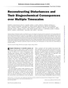
2. ATMOSPHERIC MODELING In the present study, we have used a state-of-the-art atmospheric model, called the Weather Research and Forecasting (WRF) model,3 to reconstruct the meteorological conditions around the time of Titanic disaster. The WRF model is a non-hydrostatic mesoscale model and is capable of simulating a plethora of atmospheric phenomena ranging from hurricanes4 to low-level jets;5 from von K´arm´an vortex streets6 to tornado outbreaks.7 Version 3.4.1 of the WRF model is employed in this study in conjunction with the following physics parameterizations: (i) planetary boundary layer (PBL): MellorYamada-Nakanishi-Niino (MYNN);8 (ii) surface layer: Monin-Obukhov similarity-based scheme;9 (iii) land surface: Noah scheme;10 (iv) shortwave and longwave radiation: Rapid Radiative Transfer Model for Global Climate Models (RRTMG) scheme;11, 12 (v) microphysics: WRF Single-Moment 5-class scheme;13 and (vi) cumulus: Kain-Fritsch scheme.14, 15 In order to quantify the sensitivity of the simulated results with respect to turbulence parameterizations, an additional run is performed with a first-order closure scheme called the Yonsei University (aka YSU) scheme16, 17 instead of the second-order (more complex) MYNN scheme. Most of these parameterization schemes are discussed in great detail by Stensrud.18 The model domain configuration is shown in Fig. 1. The outer domain (d01) employs a horizontal grid resolution of 27 km × 27 km; whereas, the inner domain (d02) uses a grid resolution of 9 km × 9 km. In both domains, 51 non-uniformly stretched vertical levels are used. The lowest model level is at ∼ 7 m above ground level (AGL); the top of the domain is close to 16,000 m AGL. Approximately 18 vertical levels are below 1 km AGL. Land use and topographical properties for all the simulations are taken from the United States Geological Survey (USGS) grid resolution.
50 °N
40 °N
30 °N
20 °N
10 °N
70'W
60 "W
50051
40`W
30 °W
Figure 1. One-way nested model domains are utilized in this study. The outer (d01) and inner domains (d02) have horizontal grid sizes of 27 km and 9 km, respectively. The boundary of the inner domain is marked with solid white lines. The outer domain is extensive and largely covers the Atlantic ocean in order to accurately simulate the largescale atmospheric motions.
dataset at resolutions comparable with the horizontal
Similar to all computational fluid dynamics models, the WRF model requires initial and boundary condition data to initiate and time integrate atmospheric simulations. For the case study presented here, the WRF model is prescribed meteorological initialization conditions from the Twentieth Century reanalysis (henceforth 20CR) dataset.19 This unique dataset contains meteorological data from from the year 1871 to the present day with a spatial resolution of 2 degrees and a temporal resolution of 6 h. Based on Maltin’s theory, sea-surface temperature (SST) was one of the environmental conditions which was key to the unique optical conditions on the night of the Titanic disaster. The default SST and land-surface temperature (LST) fields from the 20CR dataset, mapped on the WRF’s outer domain, is shown in the left panel of Fig. 2. The SST value near the Titanic’s disaster site is around 8◦ C, which is much warmer than the near-freezing temperatures recorded by the ship logs (see Howells,20 Lawrence21). Clearly, the SSTWRF-20CR field does not represent the southern coverage of the cold Labrador current very well. To rectify this obvious discrepancy, we make use of the more detailed International Comprehensive Ocean-Atmosphere Data Set (ICOADS; http://icoads.noaa.gov/). This extensive dataset (spanning the past three centuries) contains surface marine data including ship-based observations. A simple spatial adjustment method ( similar to the approach by Brandes22 ) is used to synthetically merge 20CR and ICOADS datasets. First, using bi-linear interpolation, SSTWRF-20CR values are interpolated to the ICOADS data sites. Then, SST correction factor (i.e., SSTCorrection = SSTICOADS /SSTWRF-20CR ) is calculated for each of these ICOADS sites. After this operation, bi-linear interpolation is once again used to create a two-dimensional field of SSTCorrection for the the WRF model’s grid locations. Finally, the SSTWRF-20CR values are multiplied by the corresponding interpolated
Proc. of SPIE Vol. 9224 92240Y-2 Downloaded From: http://proceedings.spiedigitallibrary.org/ on 10/08/2014 Terms of Use: http://spiedl.org/terms
correction terms. The merged SST field is shown in the right panel of Fig. 2 and is used as a lower boundary condition for all the WRF simulations. Please note that, in contrast to the static SST field, the land surface temperature (LST) field evolved dynamically with every simulation time-step. Skin Tomeeratuto (CI
),
Iran* . ' ,WP
.
sarionr ' c0w
ee°w
Skin Tenpeature
-14 -12 -10 -8
-6
-4
-2
0
2
4
6
8
10
12
11
16
18 20 22 24
70'w
60'W
so°w
40'W
m ^w
Skin Tempe'amre (CI
14 -12 -10 -8 -6
-4
-2
0
2
4
6
8
10 12
14
16
18 20 22 24
Figure 2. Left panel: sea-surface and land-surface temperature fields from the 20CR dataset. Right panel: the same surface temperature fields from the merged 20CR and ICOADS datasets. The location of Titanic’s disaster is shown as a red circle with a cross symbol. These surface temperature fields represent 0 UTC, April 12, 1912.
The WRF model-based simulations are run for a total of 96 h with the first 24 h being used as spin-up time. The simulation start time is 0 UTC on April 12, 1912. The integration time-steps are 90 s and 30 s for the outer and inner domains, respectively. The method of grid-nudging23 is employed for flow fields above the boundary layer height. This computational strategy enables the WRF model-generated large-scale atmospheric patterns to remain conformed to the corresponding 20CR fields. At the same time, the smaller-scale motions (especially in the boundary layer), in the WRF domains, dynamically evolve more realistically due to finer grid-resolution and physically-based parameterizations. The WRF model-generated synoptic charts are shown in Fig. 3. The left and right panels represent 0 UTC of April 13 and April 16, respectively. Qualitatively, these simulated charts look very similar to the observational ones reported by Lawrence.21 The presence of high pressure over the North Atlantic for the entire period of April 13-16 is quite clear. On April 13, the near-surface flow was from the south-west at Titanic’s disaster location. However, with progression in time, the flow was more from the north-west (due to the presence of a low-pressure center over Greenland), and therefore, brought in bitterly cold polar air to the region. At the time of the sinking, an extremely high Arctic pressure center (1035 mb) was almost collocated with the disaster zone. Relatively calm wind and clear sky were associated with this anomalously high pressure situation.21 The simulated air-surface temperature difference (ASTD) fields are shown in Fig. 4. The left panel represents 12 UTC, April 13. At this time the cold front has not passed through Titanic’s location and the ASTD values are largely positive. In other words, air is a few degrees (approximately 2◦ C) warmer than the sea-surface at this time. However, around the time of the Titanic’s disaster, the cold front has already passed through the location of interest. Thus, the ASTD field becomes negative around that location (right panel of Fig. 4).
Proc. of SPIE Vol. 9224 92240Y-3 Downloaded From: http://proceedings.spiedigitallibrary.org/ on 10/08/2014 Terms of Use: http://spiedl.org/terms
Figure 3. The WRF model-generated synoptic fields at 0 UTC, April 13, 1912 (left panel) and 0 UTC, April 16, 1912 (right panel). The location of Titanic’s disaster is shown as a red circle with a cross symbol. The YSU PBL scheme is used in this WRF run.
For comparison, observed air and sea-surface temperature maps, reported by Howells,20 are shown in Fig. 5. It is clear that during the time of the disaster, the observed ASTD near Titanic’s location was close to zero. Strong super-refractive condition, as conjectured by Maltin, is not physically feasible when ASTD is close to zero or negative. The time-height plots shown in Fig. 6 provide another view of the evolution of the temperature field at the Titanic’s location. Prior to April 14, the upper layer temperatures are significantly warmer than the very nearsurface temperatures. This is due to the fact that the warm Gulf air from the south-west was blowing over this location. The surface temperature was cold due to the presence of the Labrador current. However, soon after 0 UTC on April 14, a cold front moved through the region. This front very quickly displaced the warmer air aloft. For this reason, the ASTD field near the surface became negative representing unstable (weakly convective) condition. The impacts of this meteorological condition on refraction and optical turbulence are described in the following sections.
3. OPTICAL RAY TRACING Since the simulated ASTD field is negative at the time and location of Titanic’s sinking, super-refraction is not physically possible. However, in this section we will demonstrate that during the pre-frontal passage, superrefraction is highly possible in the same region. We use conventional ray tracing24 to demonstrate this effect. The numerical results yielded from the WRF simulations are first used to compute refractive index (n) as a function of wavelength (λ) at all locations within the domain using Eq. 1. nλ − 1 =
1 [AD (λ)PD + AW (λ)PW ]. T
Proc. of SPIE Vol. 9224 92240Y-4 Downloaded From: http://proceedings.spiedigitallibrary.org/ on 10/08/2014 Terms of Use: http://spiedl.org/terms
(1)
ASTI/ (C) Sea Level Pressure (hPa)
ASTI) (C) Sea Level Pressure (hPa) Wind (m /s)
Wine (Ws)
50 °N -
45 °N -
40 °N -
35 °N -
30 °N -
25 °N -
70 °W
F40 °W
50 °W
60 °W
30 °W
60IW
70 °W
-4
-3
-2
-1
0
1
2
3
11-
30 °W
Sea Level Pressure Contours: 900 to 1100 by 4
ASTO (C)
ASID (C)
-5
40 °W
50 °W
Sea Level Pressure Contours: 900 to 1100 by 4
4
5
4
2
1
0
1
2
3
4
5
Figure 4. The WRF model-generated ASTD fields at 12 UTC, April 13 (left panel) and 0 UTC, April 15 (right panel). The air temperature is from the lowest model level at ∼ 7 m AGL. The location of Titanic’s disaster is shown as a red circle with a cross symbol. The MYNN PBL scheme is used in this WRF run.
Here, T is temperature (K) and PD and PW represent the partial pressures (hPa) of dry air and water (respectively). The corresponding reduced refractivities are AD and AW . We define AD and AW using the equations suggested by Ciddor25 (i.e., Eqs. 2 and 3). AD (λ) = 10−8 [5792105(238.0185 − 1/λ2 )−1 + 1167917(57.362 − 1/λ2 )−1 ]
The vertical cross-section of temperature (left panel) and refractivity gradient (right panel) along the locations of Titanic and Californian are shown in Fig. 7. At 0 UTC, April 14, the surface inversion was deeper over Californian. Over Titanic’s location, due to the proximity of the Gulf stream, the surface inversion was shallower. The refractivity field shows very strong vertical gradient below 50 m AGL. Strong bending of rays, delineating super-refraction, is clearly visible in Fig. 7.
4. OPTICAL TURBULENCE The intensity of optical turbulence is traditionally characterized by the refractive index structure parameter (Cn2 ). In this work, we estimate Cn2 utilizing a subset of output fields (i.e., the energy dissipation rate and the molecular destruction of temperature variance) from the MYNN PBL scheme. The horizontal cross-sections of log10 Cn2 at a height of 100 m AGL are shown in Fig. 8. At 0 UTC, April 14, the spatial field shows the signature of intermittent turbulence, especially slightly north of Titanic’s disaster location. Such sporadic condition could potentially distort Morse lamp signals. However, according to our simulation, such spatial intermittency is
Proc. of SPIE Vol. 9224 92240Y-5 Downloaded From: http://proceedings.spiedigitallibrary.org/ on 10/08/2014 Terms of Use: http://spiedl.org/terms
70°M
50°N St John's 50°N
Air tem
40 °N
c.03h 15 APR 1912
60°W
so,
60°W
60°W
Figure 5. Contour maps of observed air (left panel) and sea-surface temperatures (right panel) at 3 UTC, April 15. The plots are based on ship observations taken between 0 UTC and 6 UTC on April 15. These plots are taken from Howells.20
Ternperature
K
285
600
280
400
275
c7)
=
200
270
461111PA 12
13
14
15
16
265
Date (April, 1912) Figure 6. Time-height plot of temperature at the location of Titanic’s disaster. The MYNN PBL scheme is used in this WRF run.
absent at the time of 0 UTC, April 15 (i.e., post-frontal passage). This is due to the fact that a weakly unstable condition was prevalent at this time near the lower part of the marine boundary layer. The time-height plot of log10 Cn2 at the location of Titanic’s disaster is shown in Fig. 9. Prior to the frontal passage, optical turbulence was only present in the near-surface region. However, after 0 UTC, April 14, optical turbulence spread over larger depths. Additionally, a significant amount of turbulence is visible at the interface between the cold front and the pre-existing Gulf air.
5. CONCLUDING REMARKS AND FUTURE DIRECTIONS In this study, we utilized the WRF model to simulate meteorological conditions prevailing during the Titanic disaster. The simulation was able to capture: (i) the evolution of an Arctic high pressure center, (ii) the
Proc. of SPIE Vol. 9224 92240Y-6 Downloaded From: http://proceedings.spiedigitallibrary.org/ on 10/08/2014 Terms of Use: http://spiedl.org/terms
K 250
m 285
250
200
1
x 10
-1
200 280
E 150 .c
-2
E 150
c»
2
=
100
100
3
50
4
275 50
270
0 0
10
20
30
40
0
J
0
10
Distance (km)
20
30
40
50
-5
60
Distance (km)
Figure 7. Left panel: vertical cross-section of temperature (K) between the locations of Titanic and Californian at 0 UTC, April 14 (pre-frontal passage). Right panel: ray tracing along the same vertical cross-section. The height of the ray origin is 30 m. The gradient of refractivity (m−1 ) is shown in the background.
passage of a cold front, (iii) the spatio-temporal distribution of wind fields, and (iv) highly refractive layer and intermittent optical turbulence. Furthermore, the ray tracing simulations portray signatures of super-refraction; however, the timing was several hours prior to the Titanic’s disaster. The observed (reported by Howells20 ) and simulated results (present study) do not support do not support super-refractive conditions at the time and place of Titanic’s disaster, as conjectured by Maltin.1 While the simulated results presented here verified reasonably well with historical synoptic weather records, it is important to point out that our simulations, like all atmospheric simulations, suffer from some degree of uncertainty. Most notably, we expect that factors such as initial and boundary conditions, horizontal and vertical grid resolutions, turbulence parameterization, atmospheric-oceanic coupling, and the parameterization of icebergs to be possible important sources of uncertainty in our simulations. We intend to quantify the levels of uncertainty associated with a few of these areas in the near-future.
ACKNOWLEDGMENTS The authors acknowledge financial support received from the Department of Defense AFOSR under award number (FA9550-12-1-0449). Any opinions, findings and conclusions or recommendations expressed in this material are those of the authors and do not necessarily reflect the views of the Department of Defense.
Proc. of SPIE Vol. 9224 92240Y-7 Downloaded From: http://proceedings.spiedigitallibrary.org/ on 10/08/2014 Terms of Use: http://spiedl.org/terms
loge OiCN21 a: 100 rr AGI
log 1010N2) a! 100m NGL
50'N -
45.N -
s°
1414. }}}
J,FAh
S''
,,.y,-' M A
40.N -
.1.v C' ..
35'N -
30 "N -
25.N -
60IW
70 "W
50°W
40°W
30 °W
1o910(CN2) at 100 m AGL
-17 -16.5
-16
-15.5
-15 -14.5 -14 -13.5
log10(CN2) at 100 m AGL -13 -12.5
-12
-17 -16.5 -16 -15.5 -15 -14.5
-14
-13.5 -13 -12.5
Figure 8. Horizontal cross-section of log10 Cn2 at a height of 100 m AGL. The left and right panels represent 0 UTC, April 14 and 0 UTC, April 15, respectively. The location of Titanic’s disaster is shown as a red circle with a cross symbol. The MYNN PBL scheme is used in this WRF run.
log 1
o(C2 n)
600
.-,
-14
400
-15
_c
200
12
-16 13
14
15
16
-17
Date (April, 1912) Figure 9. Simulated time-height plot of log10 Cn2 at the location of Titanic’s disaster. The MYNN PBL scheme is used in this WRF run.
Proc. of SPIE Vol. 9224 92240Y-8 Downloaded From: http://proceedings.spiedigitallibrary.org/ on 10/08/2014 Terms of Use: http://spiedl.org/terms
REFERENCES 1. Maltin, T., [Titanic: A Very Deceiving Night ], Malt House Publishing (2012). 2. Darack, E., “Titanic’s mirage: A new perspective on one of history’s greatest mysteries,” Weatherwise 66(2), 24–31 (2013). 3. Skamarock, W. C., Klemp, J. B., Dudhia, J., Gill, D. O., Barker, D. M., Duda, M. G., Huang, X.-Y., Wang, W., and Powers, J. G., “A description of the Advanced Research WRF version 3,” Tech. Rep. NCAR/TN-475+STR, National Center for Atmospheric Research (2008). 4. Davis, C., Wang, W., Chen, S. S., Chen, Y., Corbosiero, K., DeMaria, M., Dudhia, J., Holland, G., Klemp, J., Michalakes, J., et al., “Prediction of landfalling hurricanes with the advanced hurricane WRF model,” Monthly weather review 136(6), 1990–2005 (2008). 5. Storm, B., Dudhia, J., Basu, S., Swift, A., and Giammanco, I., “Evaluation of the Weather Research and Forecasting model on forecasting low-level jets: implications for wind energy,” Wind Energy 12(1), 81–90 (2009). 6. Nunalee, C. G. and Basu, S., “On the periodicity of atmospheric von K´arm´an vortex streets,” Environmental Fluid Mechanics , 1–21 (2013). 7. Shafer, C. M., Mercer, A. E., Doswell III, C. A., Richman, M. B., and Leslie, L. M., “Evaluation of WRF forecasts of tornadic and nontornadic outbreaks when initialized with synoptic-scale input,” Monthly Weather Review 137(4), 1250–1271 (2009). 8. Nakanishi, M. and Niino, H., “An improved Mellor–Yamada level-3 model: its numerical stability and application to a regional prediction of advection fog,” Boundary-Layer Meteorology 119(2), 397–407 (2006). 9. Jim´enez, P. A., Dudhia, J., Fidel Gonz´ alez-Rouco, J., Navarro, J., Mont´ avez, J. P., and Garc´ıa-Bustamante, E., “A revised scheme for the WRF surface layer formulation,” Monthly Weather Review 140(3), 898–918 (2012). 10. Chen, F. and Dudhia, J., “Coupling an advanced land surface-hydrology model with the Penn State-NCAR MM5 modeling system. part i: Model implementation and sensitivity,” Monthly Weather Review 129, 569– 585 (2001). 11. Iacono, M. J., Delamere, J. S., Mlawer, E. J., Shephard, M. W., Clough, S. A., and Collins, W. D., “Radiative forcing by long-lived greenhouse gases: Calculations with the AER radiative transfer models,” Journal of Geophysical Research: Atmospheres (1984–2012) 113(D13) (2008). 12. Mlawer, E. J., Taubman, S. J., Brown, P. D., Iacono, M. J., and Clough, S. A., “Radiative transfer for inhomogeneous atmospheres: RRTM, a validated correlated-k model for the longwave,” Journal of geophysical research 102(D14), 16663–16 (1997). 13. Hong, S.-Y., Dudhia, J., and Chen, S.-H., “A revised approach to ice microphysical processes for the bulk parameterization of clouds and precipitation,” Monthly Weather Review 132, 103–120 (2004). 14. Kain, J. S., “The Kain-Fritsch convective parameterization: an update,” Journal of Applied Meteorology 43, 170–181 (2004). 15. Kain, J. S. and Fritsch, J. M., “A one-dimensional entraining/detraining plume model and its application in convective parameterization,” Journal of the Atmospheric Sciences 47(23), 2784–2802 (1990). 16. Hong, S.-Y., Noh, Y., and Dudhia, J., “A new vertical diffusion package with an explicit treatment of entrainment processes,” Mon. Wea. Rev. 134, 2318–2341 (2006). 17. Hong, S.-Y., “A new stable boundary-layer mixing scheme and its impact on the simulated East Asian summer monsoon,” Quarterly Journal of the Royal Meteorological Society 136, 1481–1496 (2010). 18. Stensrud, D. J., [Parameterization schemes: Keys to understanding numerical weather prediction models], Cambridge University Press, 459 pp. (2007). 19. Compo, G. P., Whitaker, J. S., Sardeshmukh, P. D., Matsui, N., Allan, R., Yin, X., Gleason, B., Vose, R., Rutledge, G., Bessemoulin, P., et al., “The Twentieth Century reanalysis project,” Quarterly Journal of the Royal Meteorological Society 137(654), 1–28 (2011). 20. Howells, D., “The maiden voyage of the Titanic – a meteorological perspective,” Weather 47(11), 417–423 (1992). 21. Lawrence, E., “The Titanic disaster – a meteorologist’s perspective,” Weather 55(3), 66–78 (2000).
Proc. of SPIE Vol. 9224 92240Y-9 Downloaded From: http://proceedings.spiedigitallibrary.org/ on 10/08/2014 Terms of Use: http://spiedl.org/terms
22. Brandes, E. A., “Optimizing rainfall estimates with the aid of radar,” Journal of Applied Meteorology 14(7), 1339–1345 (1975). 23. Stauffer, D. R. and Seaman, N. L., “Use of four-dimensional data assimilation in a limited-area mesoscale model. part i: Experiments with synoptic-scale data,” Monthly Weather Review 118, 1250–1277 (1990). 24. Southwell, W. H., “Ray tracing in gradient-index media,” Journal of the Optical Society of America 72(7), 908–911 (1982). 25. Ciddor, P. E., “Refractive index of air: new equations for the visible and near infrared,” Applied optics 35(9), 1566–1573 (1996).
Proc. of SPIE Vol. 9224 92240Y-10 Downloaded From: http://proceedings.spiedigitallibrary.org/ on 10/08/2014 Terms of Use: http://spiedl.org/terms