Nov 16, 2009 - Recovering Architectural Views from Software Process Models. Julio Ariel Hurtado ... software process model from a small company. Some.
Recovering Architectural Views from Software Process Models Julio Ariel Hurtado Alegr´ıa Alexandre Bergel Mar´ıa Cecilia Bastarrica Computer Science Department (DCC) Universidad de Chile, Santiago, Chile {jhurtado, abergel, cecilia}@dcc.uchile.cl 1. Introduction Defining organizational software process models is necessary for improvement. However, determining whether a process model is appropriate before being enacted remains challenging, i.e., to statically verify process models instead of testing them, as suggested by [5]. For example, identifying cycles of dependencies among work products, or task cycles with no clear ending conditions are not always easily seen in complete process model specifications [2]. The convenience of specifying the software architecture with multiple views has been agreed upon [1][3], so we follow the same approach for dealing with processes. Different stakeholders require different evaluations, thus it seems natural to deal with multiple architectural views. We specify our process models using the SPEM 2.0 standard. Process architectural views are built following an architectural recovery process such that each view allows us to evaluate different process characteristics. We propose three process architectural view types: ROLE B LUEPRINT, TASK B LUEPRINT and W ORK P RODUCT B LUEPRINT.
2. Process Architecture Recovery As for most engineering activities, defining a robust and efficient software process is a non-trivial activity that requires flexible and expressive tools. As a complement to software process design tools, we provide an agile and lightweight environment for recovering, visualizing and understanding software process models. This environment is based on the Moose software analysis platform1 and the Mondrian2 visualization engine. Scripts define a visualization based on the OMG Software & Systems Process Engineering MetaModel Specification 2.0 (SPEM). Process visualization 1. http://moose.unibe.ch 2. http://moose.unibe.ch/tools/mondrian
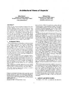
scripts use a domain specific language and are usually short (< 10 lines of code). Our experience with recovering software processes shows that there is no unique “perfect” view to visually render a software process architecture. We identified three different views that provide great help in getting higher level representations. Role, task and work product are the central concepts in SPEM, so making the views focus on these concepts is intuitive and has the advantage to introduce no extra abstraction. A polymetric view [4] is a lightweight software visualization technique enriched with software metrics information. It consists of a graph where domain elements are nodes and the relation between these elements are edges. Graph aspect variables (node position, size and color) are determined by computing some metrics. The three polymetric views we identified for recovering process architecture are examplified in Figure 1. For the sake of conciseness, name of elements have been ommitted from the figure. The blueprints were used for analyzing an example software process model from a small company. Some problems have been identified and the company is currently taking appropriate actions to solve them. ROLE B LUEPRINT. An edge designates a collaboration between two roles. Two roles collaborate if they work on the same task. The size of a role represents the quantity of tasks this role is in charge of. In the figure, this view reveals an interesting situation for the case: there is a “small” role that is not connected with other roles. By inspecting which role it is, we saw that it corresponds to the client role. This means that the client is not collaborating with other roles whereas it should at least collaborate with the analyst and the tester in the analysis and testing tasks, respectively. TASK B LUEPRINT. A box represents a task and an edge designates an order dependency between two tasks: T1 depends on T2, if T1 uses a work product produced by T2. The size of a task represents the number of work
RoleBlueprint
WorkProductBlueprint
TaskBlueprint
Figure 1. Process architecture visualization
products required and produced. The example view in the figure reveals an anomalous situation for the case: there exist some isolated tasks and task groups, so it is not possible to interpret the model, and neither to validate its execution order. Although task connections are not required in SPEM 2.0 because the connection is realized between the Task Use, we still need a coherent relationship between tasks and their related work products. Likewise, cycles without entrance and exit tasks are present; this means that it is not possible to determine previous and following tasks of the cycle, and neither when a cycle must end. W ORK P RODUCT B LUEPRINT. Each work product of the analyzed process model is a node in the view. A work product W1 depends on W2, if W1 is an output of a task where W2 is input. Here we can also find isolated sets of work products, i.e., a process model is defined as a set of unconnected process areas, and not as a coherent and complete process model. For example for producing test cases, the use cases are necessary, however this is not defined in the process model. So, we were able to discover that the example process model is incomplete. Lesson learned. We assessed a number of popular agile software processes (Open UP, XP and Scrum) and two industrial software processes (Tutelkan Reference Process – a CMMI Level 2 reference process, and DTS – a small company process). These case studies show that these three architectural blueprints are a great tool to validate process models identifying incompleteness and anomalies. We identified a number of problems in
these processes, which are currently under consideration for improving process model descriptions. This approach has a high potential for verifying process models in other domains, e.g. business process models.
References [1] P. Clements, F. Bachmann, L. Bass, D. Garlan, J. Ivers, R. Little, R. Nord, and J. Stafford. Documenting Software Architectures. Addison-Wesley, 2002. [2] D. Jacobs and C. Marlin. Multiple view software process support using the MultiView architecture. In ISAW-2 and Viewpoints ’96, pages 217–221. ACM, 1996. [3] D. Jacobs and C. D. Marlin. Software process representation to support multiple views. IJSEKE, 5(4):585–597, 1995. [4] M. Lanza and S. Ducasse. Polymetric Views-A Lightweight Visual Approach to Reverse Engineering. TSE, 29(9):782–795, Sept. 2003. [5] L. J. Osterweil. Software Processes Are Software Too. In 9th ICSE, pages 2–13. ACM Press, 1987.
About the Authors. Julio Ariel Hurtado Alegr´ıa is a PhD student at the DCC, Univ. de Chile. His interest is software process modeling. Alexandre Bergel is an Assistant Professor at DCC, Univ. de Chile. His interest is software visualization. Mar´ıa Cecilia Bastarrica is an Assistant Professor at DCC, Univ. de Chile. Her insterest is software architecture.