Jun 17, 2011 - based network link failure recovery, the two nodes at the end of the failed link can switch .... detected, the data can be immediately recovered.
Recovery from Link Failures in Networks with Arbitrary Topology via Diversity Coding Serhat Nazim Avci, Xiaodan Hu, and Ender Ayanoglu
arXiv:1106.0489v2 [cs.NI] 17 Jun 2011
Center for Pervasive Communications and Computing Department of Electrical Engineering and Computer Science University of California, Irvine Abstract—Link failures in wide area networks are common. To recover from such failures, a number of methods such as SONET rings, protection cycles, and source rerouting have been investigated. Two important considerations in such approaches are the recovery time and the needed spare capacity to complete the recovery. Usually, these techniques attempt to achieve a recovery time less than 50 ms. In this paper we introduce an approach that provides link failure recovery in a hitless manner, or without any appreciable delay. This is achieved by means of a method called diversity coding. We present an algorithm for the design of an overlay network to achieve recovery from single link failures in arbitrary networks via diversity coding. This algorithm is designed to minimize spare capacity for recovery. We compare the recovery time and spare capacity performance of this algorithm against conventional techniques in terms of recovery time, spare capacity, and a joint metric called Quality of Recovery (QoR). QoR incorporates both the spare capacity percentages and worst case recovery times. Based on these results, we conclude that the proposed technique provides much shorter recovery times while achieving similar extra capacity, or better QoR performance overall.
I. I NTRODUCTION Failures in communication networks are common and can result in substantial losses. For example, in the late 1980s, the AT&T telephone network encountered a number of highly publicized failures [1], [2]. In one case, much of the long distance service along the East Coast of the U.S. was disrupted when a construction crew accidentally severed a major fiber optic cable in New Jersey. As a result, 3.5M call attempts were blocked [1]. On another occasion, of the 148M calls placed during the nine-hour-long period of the failure, only half went through, resulting in tens of millions of dollars worth of collateral damage for AT&T as well as many of its major customers [2]. Observing that such wide-scale network failures can have a huge impact, in February 1992, the Federal Communications Commission (FCC) of the U.S. issued an order requesting that carriers report any major outages affecting more than 50K customers lasting for more than 30 minutes. Over a decade, the reports made available to the public showed that network failures are very common and cause significant service interruptions. According to the publicly available data, while most of the reported events impacted up to 250K users, some impacted millions of users [3]. In the early 1990s, AT&T decided to address the restoration problem for its long distance network with an automatic This work is partially supported by NSF under Grant No. 0917176
centrally controlled mesh recovery scheme, called FASTAR, based on digital cross-connect systems [4]. Since then, this subject has seen a significant amount of research. In meshbased network link failure recovery, the two nodes at the end of the failed link can switch over to spare capacity. Alternatively, all the affected paths could be switched over to spare capacity in a distributed fashion. While the former is faster, the latter will have smaller spare capacity requirement. In this paper, we will use the term source rerouting to refer to mesh-based link or path protection algorithms. In simulations we employ the Simplest Spare Capacity Allocation (SSCA) algorithm [5]. In the mid-1990s, specifications for an automatic protection capability within the Synchronous Optical Networking (SONET) transmission standard were developed. These later became the International Telecommunications Union (ITU) standards G.707 and G.708. The basic idea for protection is to provide 100% redundant capacity on each transmission path through employment of ring structures. SONET can accomplish fast restoration (telephone networks have a goal of restoration within 50 ms after a failure to keep perception of voice quality unchanged by human users) at the expense of a large amount of spare capacity [6], [7]. The restoration times for mesh-based rerouting techniques are typically larger than those of SONET rings, however, the extra transport capacity they require for restoration in the U.S. is generally better than that achievable by SONET rings. In late 1990s, with other major U.S. long distance carriers moving to SONET rings for restoration purposes, an industry-wide debate took place as to whether the mesh-based restoration or the SONET ringbased restoration is better. This debate still continues today. Although most researchers accept that mesh-based restoration may save extra capacity, restoration speeds achievable with mesh-based restoration are generally low and the signaling protocols needed for message feedback are an extra complexity that can also complicate the restoration process. An extension of the SONET rings is the technique known as p-cycles [8]. In a network, a p-cycle is a ring that goes through all the nodes once. Such a ring will provide protection against any single link failure in the network because there is always an alternative path on the ring that connects the nodes at the end of the failed link, unaffected by the failure. The recovery is carried out by the two nodes that detect the failure at the two ends of the failed link. These nodes reroute the traffic on this link to the corresponding part of the p-cycle. Constructing p-cycles and the corresponding spare capacity
d1 d2 dN
. . .
- d1 - d2 ?? .N.. ?
1
=
Mj j =1
d
.. .
- dN -
1
- d1 - d2
. . .
...
? ??
Failure Dete tor (a)
-
.. ?? .M N ?
1
�
j =1 j =i
dj
. . .
- dN - di
6 6
i
(b)
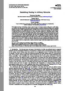
Fig. 1. Diversity coding where N parallel data links are protected against failure by one coded link. (a) Encoder and (b) Decoder.
assignment can be solved by a number of algorithms [8]. Some of these algorithms employ linear programming while there are a number of simpler design algorithms. In this paper, we employ the algorithm in [8, p. 699], which is considered to be within 5% of the optimal solution [8]. We would like to add that in the technique of p-cycles, it is possible to subdivide the network nodes and generate different p-cycle rings for each division separately [8]. Recovery from link failures in IP networks can take a long time [7] becasue IP routing protocols were not designed to minimize network outages. There has been Internet research that shows a single link failure can cause users to experience outages of several minutes even when the underlying network is highly redundant with plenty of spare bandwidth available and with multiple ways to route around the failure [7]. Needless to say, depending on the application, outages of several minutes are not acceptable, for example, for IP telephony, ecommerce, or telemedicine. Within the telephony transmission and networking community, hitless restoration from failures is often described as an ideal [8]. Nevertheless, with the methods considered, it could not be achieved because these methods are based on message feedback and rerouting, both of which take time. Whereas, with our method, hitless or near-hitless recovery from single link failures becomes possible given delay buffers that synchronize the paths. This introduces non-appreciable transmission delay. The basic technique is powerful enough that it can be extended to other network failures such as multiple link or node failures. The concept of a Quality of Recovery (QoR) metric was introduced previously in order to find an overall metric that evaluates the performance of a protection technique and compares it with others, see e.g., [9]. The arguments of the QoR metric depend on the problem and its application. In this paper, we employ a version of the QoR metric from [9] that incorporates spare capacity percentage, restoration time, and data loss. II. D IVERSITY C ODING The basic idea in diversity coding is given in Fig. 1 [10], [11]. Here, digital links of equal rate d1 , d2 , . . . , dN are transmitted over disjoint paths to their destination. For the sake of simplicity, assume that these links have a common source and a common destination, and have the same length.
A “parity link” c1 equal to c1 = d1 ⊕ d2 ⊕ · · · ⊕ dN =
N M
dj
j=1
is transmitted over another equal length disjoint path. In the case of the failure of link di , the receiver can immediately form N N M M (dj ⊕ dj ) = di dj = di ⊕ c1 ⊕ j=1 j6=i
j=1 j6=i
since it has d1 , d2 , . . . di−1 , di+1 , . . . , dN available and dj ⊕ dj = 0 in modulo-2 arithmetic or logical XOR operation. As a result, di is recovered by employing c1 and d1 , d2 , . . . , di−1 , di+1 , . . . , dN . It is important to recognize that this recovery is accomplished in a feedforward fashion, without any message feedback or rerouting. We assumed above that the sources and the destinations of d1 , d2 , . . . , dN , c1 are the same. Diversity coding can actually be extended into network topologies where the source or the destination node is not common. Some examples of such network topologies include multi-point to point, point to multi-point and multi-point to multi-point connections. In some cases, there may be a designated encoding node and a designated decoding node, whereas in some other cases encoding operation can be carried out in source nodes in an incremental fashion. Decoding operation also can be done only at destination nodes, instead of a designated intermediate node. Examples of these topologies can be found in [10], [11], [12]. Diversity coding papers [10], [11] predate the work that relate the multicast information flow in networks to the minimum cut properties of the network [13] by about a decade. This latter work has given rise to the general area of network coding. However, in network coding, discovery of optimal techniques to achieve multiple unicast routing in general networks has remained elusive. In this paper, we provide a systematic approach to the related problem of designing an overlay network for link failure recovery in arbitrary networks, based on [10], [11]. As stated above, the main advantage of diversity coding as a recovery technique against failures in networks is the fact that it does not need any feedback messaging. Whereas, meshbased source rerouting techniques, SONET rings, and the technique of p-cycles do need signaling protocols to complete rerouting. With diversity coding, as soon as the failure is detected, the data can be immediately recovered. As in network coding, this requires synchronization of the coded streams. We refer the reader to [10] for a description of the need for synchronization as well as how to achieve it in diversity coding. A. Example 1 We will now provide a simple example regarding the use of diversity coding for link failure recovery. Consider the network in Fig. 2(a). This network has a similar topology to the wellknown butterfly network commonly used to illustrate the basic
S1
S1
S2 A
2
2
S2 A
B
c
a
B
a+c 1
A
A+B
B
A
A+B
5
4
1
a+b
5
4
B b+d
A
failure
B
0
B
b 3 (a)
0
D1
0
A
D1
D2
A
2 a or b
S1
A
0
A B
B
(c)
Fig. 2.
B
A+B
A
failure
D2
B
A+B
2
c
a, p a, p
5
4
1
5
b, d
B
A+B D 2
(d)
A simple example for link failure recovery via diversity coding.
concept of multicasting via network coding, first appeared in [13]. In this example, the source node S1 wishes to transmit its data A to destination node D1 and the source node S2 wishes to transmit its data B to destination node D2 , shown by solid lines. The restoration network is shown via dashed lines. There is an encoder on top which forms A ⊕ B which we show as A + B. This data is then transmitted to the decoder node. The decoder forms the summation of the data received from the encoder and the two destination nodes. In the case of failures, some of these data will not be present. However, the network is designed such that the destination node will automatically receive the missing data from the restoration network in an automatic fashion. In this example, the central decoder does not carry out any failure detection. This task is carried out by the destination nodes D1 and D2 as described below. In the case of regular operation, the destination nodes receive their data from their data links and receive “0” from the restoration network, as shown in Fig. 2(a). Assume the link from S1 to D1 carrying data A failed. In this case, both of the nodes D1 and D2 receive data A automatically from the restoration network, as shown in Fig. 2. Node D1 uses this data instead of what it should have been receiving directly from node S1 . Since node D2 is receiving its regular data B directly from S2 , it ignores the data transmitted by the central decoder. The symmetric failure case for the link from S2 to D2 is shown in Fig. 2(c). Other failure scenarios will be ignored by D1 and D2 since in those cases they receive their data directly from the respective sources S1 and S2 . An example of this latter mode of operation is depicted in Fig. 2(d). B. Example 2 In this example, we will show that diversity coding can result in less spare capacity than source rerouting or p-cycles. Refer to Fig. 3(a). This figure shows the available topology of
4
b, p b, p
b
failure B
A
D1
a
1
c
a or b or c
S2 A
B
A+B
D1
S1
S2 A
d
D2
(b)
(a)
3 (b)
d
3 (c)
Fig. 3.
3 (d)
d
Spare capacity comparison example.
the network. In this network, each link is bidirectional. There are 4 unit rate flows in the network represented as a, b, c, and d, where a and b are from node 1 to node 4, c is from node 2 to node 4, and d is from node 3 to node 4. The solution for diversity coding is shown in Fig. 3(b). In this solution, path 1-5-4 is a spare link for the protection of either a or b, and it carries modulo-2 sum of a and b. Note that coded signals are not limited to spare links, as the modulo-2 sum of a and c is delivered over the primary path of a. The same applies to the primary path of b. The signals are coded in such a way that node 4 can derive a, b, c, and d given any four of the five incoming links form a full-rank matrix if the remaining link failed. Fig. 3(c) represents the best solution in the case of source rerouting. The upper link is used to protect any failure in transmitting a, b or c. The lower link between nodes 3 and 4 is used to protect flow d. Different from the previous case, we need two unit capacity over the upper link between nodes 3 and 4 due to transmission of b and d separately. The best solution for p-cycles is given in Fig. 3(d). In this solution, there is only one ring that protects every signal. Due to the intermediate node 5, the p-cycles solution cannot offer protection for the path 1-5-4. Protection capacity p, which is unit rate, on the cycle is reserved to carry any failed signal a, b, c, and d since a failure affects at most one of these signals. This guarantees full operation after any failure recovery with an extra cost with respect to diversity coding. Clearly, in this example, both of the approaches of source rerouting and p-cycles result in more spare capacity as compared to the approach of diversity coding. III. C ODING
IN
N ETWORKS
WITH
A RBITRARY T OPOLOGY
We will now apply the technique described in the previous section to the design of an overlay network for recovery from link failures in arbitrary networks. We approach this problem by examining all possible combinations of standard diversity coding [10], [11], [12]. In doing this, our goal is to come up with a network for which the spare capacity introduced due to diversity coding is minimized. We employ redundancy
ratio [12], as the metric that will quantify the efficiency of a particular combination chosen. Redundancy ratio measures the extra capacity introduced in diversity coding. Due to space limitations, we refer the reader to [12] for its definition. A. Proposed Algorithm We will now discuss how we utilize the redundancy ratio of each diversity coding combination in designing an efficient diversity coding scheme for a network with arbitrary topology. The proposed algorithm is intended to search for all possible diversity coding combinations and select those with the smallest redundancy ratio. To that end, we employ a variable called Threshold. The threshold begins with a small value (ThrsdLow). Diversity coding combinations of N working paths with redundancy ratio values smaller than Threshold are accepted, and then Threshold is incremented up to its maximum value (ThrsdHgh.) Within this process, the value N is decremented from a maximum of Nmax down to 2. The set of unprotected paths is called the DemandMatrix, and when N working paths satisfying the redundancy ratio are found, they are taken out of DemandMatrix. At the end, a number of paths may remain uncoded. We protect every such path by a dedicated spare path which carries the same data, known as 1+1 APS (Automatic Protection Switch). A description of the algorithm is given under the heading Algoritm I. In our simulations for this paper, the numerical values used are ThrsdLow = 1.6, ThrsdHgh = 3.0, and Nmax = 4. IV. P ERFORMANCE M ETRICS SCP , RT , AND QoR There are two dominant factors that specify the performance of a protection technique. These are spare capacity percentage SCP and restoration time RT . The QoR metric combines these quantities into a single one and presents a clearer comparison among restoration techniques. The values of SCP are calculated via simulations over sample networks and traffic, which are given in the next section. We employ the following formula for calculating SCP in all simulations SCP =
Total Capacity-Shortest Working Capacity . Shortest Working Capacity
Shortest Working Capacity is the total capacity when there is no protection and the traffic is routed over shortest paths. The restoration time RT is defined as the longest duration that the connection is lost during the recovery process. RT is calculated by a modified version of a formula from [14]. For source rerouting, p-cycles, and diversity coding algorithms, the following formulas are used to calculate the restoration time, in respective order RTsr = F + nP + (n + 1) · D + (m + 1) · C + 3 · P + 3 · (m + 1) · D + EP RTpc = F + (n + 1) · D + 2 · C + P + EP RTdc = F + 2 · D + P D. As in [14], we use F : the time to detect a failure, D: node message processing time, C: time to configure a network
A LGORITHM I: C ODE A SSIGNMENT FOR L INK FAILURE R ECOVERY VIA D IVERSITY C ODING for Threshold=ThrsdLow to ThrsdHgh do for all combinations of N = Nmax , . . .,3,2 do if diversity ratio of combination ≤ Threshold then if f low1 , . . . , f lowK ∈ DM then for i = 1 to K do DM = DM − {f lowi } end Update the total, working, and space capacities end end end end for all f lowk ∈ DM do Apply 1+1 APS protection DM = DM − f lowk Update the total, working, and space capacities end
switch, m: number of hops in the backup route, and n: number of hops from the source node of the failed link to the source. P is the propagation time for the protection path, EP is the propagation time of failure to the closest node and nP is the propagation time until the error signal reaches the source-end node. In addition, P D means propagation delay difference between link-disjoint paths in the diversity coding scheme. As in [15], we set F to 100 µs. Similarly to [14], we set the variable C a number of values, i.e., 500 µs, 1 ms, 5 ms, and 10 ms. The particular form of the QoR metric we employ is based on [9]. We define the contributions due to RT and SCP as 1 1 , QSCP = QRT = �3 2 1 + 400 · RT 1 + SCP 100
where RT is in seconds and the factor 400 accounts for setting QRT = 1/2 for RT = 50 ms [9]. Similarly, normalization with 100 is to set QSCP = 1/2 when SCP = 100. Finally, we incorporate restoration time, data loss, and spare capacity into the QoR metric as 2 · QRT + QSCP 3 where the factor 2 accounts for both restoration time and data loss, which is proportional to RT [9]. QoR =
V. S IMULATION R ESULTS In this section, we will present simulation results for link recovery techniques previously discussed, in terms of their spare capacity requirements and their restoration times. The first network studied is the European COST 239 net-
TABLE II U.S. L ONG D ISTANCE N ETWORK
1
1310
390
760
7
2
550
660 390
210
390
8
6
9 1090
220
450
340
400 300
660
350
10
920
565
11
3
US Long Distance Network, 28 nodes, 45 spans RT for different C values (ms) Scheme SCP 0.5ms 1ms 5ms 10ms Div. Coding 106% 9.5 9.5 9.5 9.5 Source Rerout. 91% 79.7 83.7 115.7 155.7 p-cycles 107% 59.6 60.6 68.6 78.6
740
320 730
600
5
320
820
30
2
820
3
4 25
Fig. 4.
20
20
European COST 239 network. Distances are in km.
5
40
1
TABLE I COST 239 N ETWORK
15
22
18 18
4
9
40
22
20
COST 239 Network, 11 nodes, 26 spans RT for different C values (ms) Scheme SCP 0.5ms 1ms 5ms 10ms Div. Coding 98% 4.8 4.8 4.8 4.8 Source Rerout. 90% 39.8 41.8 57.8 77.8 p-cycles 64% 26.1 27.1 35.1 45.1 22 28
21
40
1 32
20
3
8
16
15
20
15
18
4
21
26 11
40
48
22
5
35 15
16
17
27
21
23
33
26
18
23
7
6
9
18
20
33
25
36
32
20
42
17
62
25
40
11
46
10
60
25 58 27
24 16
20
15
32
10
12
25
28
6 18
Fig. 6.
8 7
15
Synthetic network. Distances are in miles. TABLE III S YNTHETIC N ETWORK
2
21
19
21
38
20
35
12
Synthetic Network, 9 nodes, 20 spans RT for different C values (ms) Scheme SCP 0.5ms 1ms 5ms 10ms Div. Coding 81% 0.9 0.9 0.9 0.9 Source Rerout. 100% 5.7 8.2 28.2 53.2 p-cycles 85% 2.8 3.8 11.8 21.8
14 33
13
Fig. 5.
U.S. long distance network. Distances are in tens of miles.
work whose topology is given in Figure 4 [16]. In this graph as well as the others in the sequel, the numbers associated with the nodes represent a node index, while the numbers associated with the edges correspond to the distance associated with the edge. The traffic demand is adopted from [16] and applied to the simulation. This network was previously studied in the context of link failure recovery [8]. We provide SCP and RT results for the three schemes in Table I. The second network is based on the U.S. long-haul optical network. The topology of this network is shown in Figure 5. It is based on the topology given in [5]. In order to calculate the traffic, we employed a gravity-based model [17] and assumed the traffic between two nodes is directly proportional to the product of the populations of the locations represented by these nodes. Values of SCP and RT for this network are given in Table II. The third network is one that favors diversity coding over the other two approaches in terms of spare capacity. We came up with this network in order to provide a different example than the two previous networks. The topology of this network
is given in Fig. 6. The demand in this network is set such that it is symmetric and most of it originates from and terminates at the two end nodes 1 and 9 [12]. The values of SCP and RT are provided in Table III. For this network, the best spare capacity results are obtained by employing the diversity coding approach, similarly to the case we showed in the example in Section II.B. Comparing the values of SCP for the three networks in Tables I-III, we observe that the three techniques achieve all possible SCP performance orderings, from number one to number three. On the other hand, in terms of the RT performance, the proposed technique is always substantially better. As can be observed, the improvement in RT performance can be close to or even more than an order of magnitude. It is worthwhile to observe that for the U.S. Long Distance network, the RT values with source rerouting or p-cycles are above the critical threshold of 50 ms for all values of C, the network switch reconfiguration time. For this network, values of RT are well below the 50 ms threshold when diversity coding is employed. We would like to note that RT values for diversity coding can be reduced even further. Recall that RTdc = F +2·D +P D. P D becomes equal to zero if there is one destination node and delay equalization is performed. In
1.1 P−cycle COST−239 Source Rerouting COST−239 Diversity Coding COST−239 P−cycle US Long Dist. Source Rerouting US Long Dist. Diversity Coding US Long Dist.
1
Quality of Recovery metric
0.9
0.8
0.7
0.6
0.5
0.4
0.3
0.2
0
1
2
3
4 5 6 Setup time of an OXC (ms)
7
8
9
10
(a) 1 P−cycle Synthetic Source Rerouting Synthetic Diversity Coding Synthetic
Quality of Recovery metric
0.9
0.8
0.7
0.6
0.5
0
1
2
3
4 5 6 Setup time of an OXC in (ms)
7
8
9
10
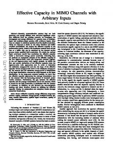
(b) Fig. 7. Quality of Recovery metric results for all three techniques (a) COST 239 and U.S. Long Distance network (b) Synthetic network.
this case, RT will become very small, about 300 µs, making the diversity coding alternative nearly hitless. As discussed earlier, it is possible to combine RT and SCP into a single metric QoR. Fig. 7 shows values of QoR for the three networks. The results show that QoR for diversity coding is better than the other techniques for all of the networks and for all possible values of the variable C. Note that while the QoR performance of source rerouting and p-cycles become worse as C increases, that of diversity coding is independent of C, because there is no rerouting involved. VI. C ONCLUSION In this paper, we employed the technique of diversity coding for providing a single link failure recovery technique in networks with arbitrary topologies. This is accomplished by finding groups of links that can be combined in basic diversity coding topologies, or in other words, mapping the arbitrary topology into efficient groups of basic diversity coding topologies. This approach results in link failure restoration schemes that do not require message feedback or rerouting and therefore are extremely efficient in terms of their restoration speed as shown via realistic calculations. Erasure coding techniques
can be employed to extend this technique to recovery from more than one link and node failures. We would like to note that a number of recent publications discuss a network coding based link recovery technique [18], [19], similar to diversity coding [10], [11], where advantages of this technique over 1+1 APS in networks are illustrated. It should be noted that, unlike the source rerouting an p-cycles techniques, 1+1 APS is not considered a network restoration technique because it is quite clear that 1+1 restoration is highly inefficient for SCP . The comparison of a technique such as diversity coding for network restoration should be made against techniques such as source rerouting or p-cycles, as carried out in this paper. R EFERENCES [1] J. C. McDonald, “Public network integrity - Avoiding a crisis in trust,” IEEE J. Sel. Areas Commun., vol. 12, pp. 5–12, January 1994. [2] “Ghost in the machine,” Time Magazine, January 29, 1990. [3] A. P. Snow and D. Straub, “Collateral damage from anticipated or real disasters: Skewed perceptions of system and business continuity risk,” in Proc. IEEE International Engineering Management Conference, vol. 2, September 2005, pp. 740–744. [4] C.-W. Chao, P. M. Dollard, J. E. Weythman, L. T. Nguyen, and H. Eslambolchi, “FASTAR - A robust system for fast DS3 restoration,” in Proc. IEEE Global Communications Conference, December 1991, pp. 1396–1400. [5] Y. Xiong and L. G. Mason, “Restoration strategies and spare capacity requirements in self-healing ATM networks,” IEEE/ACM Trans. Netw., vol. 7, pp. 98–110, February 1999. [6] S. V. Kartalopoulos, Understanding SONET/SDH and ATM: Communications Networks for the Next Millenium. Wiley-IEEE Press, 1999. [7] J.-P. Vasseur, M. Pickavet, and P. Demeester, Network Recovery: Protection and Restoration of Optical, SONET-SDH, IP, and MPLS. Elsevier, 2004. [8] W. D. Grover, Mesh-Based Survivable Networks: Options and Strategies for Optical, MPLS, SONET, and ATM Networking. Prentice-Hall PTR, 2004. [9] P. Cholda, A. Jajszcyk, and K. Wajda, “A unified Quality of Recovery (QoR) measure,” Wiley International Journal of Communication Systems, vol. 21, pp. 525–548, May 2008. [10] E. Ayanoglu, C.-L. I, R. D. Gitlin, and J. E. Mazo, “Diversity coding: Using error control for self-healing in communication networks,” in Proc. IEEE INFOCOM ’90, vol. 1, June 1990, pp. 95–104. [11] ——, “Diversity coding for transparent self-healing and fault-tolerant communication networks,” IEEE Trans. Commun., vol. 41, pp. 1677– 1686, November 1993. [12] S. N. Avci, X. Hu, and E. Ayanoglu, “Hitless recovery from link failures in networks with arbitrary topology,” in Proceedings of the Information Theory and Applications Workshop, February 2011, pp. 1–6. [13] R. Ahlswede, N. Cai, S.-Y. R. Li, and R. W. Yeung, “Network information flow,” IEEE Trans. Inf. Theory, vol. 46, pp. 1204–1216, July 2000. [14] S. Ramamurthy, L. Sahasrabuddhe, and B. Mukherjee, “Survivable WDM mesh networks,” Journal of Lightwave Technology, vol. 21, no. 4, pp. 870–883, April 2003. [15] L. Sahasrabuddhe, S. Ramamurthy, and B. Mukherjee, “Fault management in IP-over-WDM networks: WDM protection versus IP restoration,” IEEE Journal on Selected Areas in Communications, vol. 20, pp. 21–33, January 2002. [16] P. Batchelor and et al., “Ultra high capacity optical transmission networks: Final report of action COST 239,” Faculty Elect. Eng. Computing, Univ. Zagreb, Zagreb, Croatia, Tech. Rep., 1999. [17] Y. Zhang, M. Roughan, N. Duffield, and A. Greenberg, “Fast accurate computation of large-scale IP traffic matrices from link loads,” in Proc. ACM SIGMETRICS, June 2003. [18] A. Kamal and O. Al-Kofahi, “Efficient and agile 1+N protection,” IEEE Transactions on Communications, vol. 59, pp. 169–180, January 2011. [19] A. E. Kamal, A. Ramamoorthy, L. Long, and S. Li, “Overlay protection against link failures using network coding,” to be published, IEEE/ACM Transactions on Networking.