Rectangular Microstrip Patch Antenna Loaded With Double Orthogonal Crossed Slits In Ground Plane Ashish Kumar, Department of Electronics, Madhav Institute of Technology and Science Gwalior, (M.P); Bimal Garg, Department of Electronics, Madhav Institute of Technology and Science Gwalior, (M.P); Rahul Tiwari, Department of Electronics, Madhav Institute of Technology and Science Gwalior, (M.P) and Tilak Chitransh, Department of Electronics, Madhav Institute of Technology and Science Gwalior, (M.P)
Abstract— This paper propose a new generation of antenna that applies Metamaterial properties at ground Plane. Paper also analyzed the performance of Microstrip Patch Antenna with and without using the Metamaterial structure. The works mainly include Metamaterial as Defected ground plane. All antenna parameters such as Return Loss, Gain, VSWR and Band width were measured. The main focus of this paper was to improve Band width so that Patch antenna used for wide band applications. The additional features were its compact size and used in multiband operation.
weight nature, conformability to planar and non planar structures and ease of fabrication. But this type of antenna having some disadvantages also such as its narrow band width and low gain. To overcome these drawbacks we used an artificial homogeneous material called Metamaterial. According to V.G. Veselago Metamaterial [1] are artificial homogeneous materials which are not available in nature but using the properties of such a material, antenna parameters are easily improve. This paper used Metamaterial properties at ground plane to improve Band width, gain [4] and several other parameters.
Keywords- PatchAntenna, Metamaterial, Orthogonal crossed slits, Band width
Introduction Antennas are indispensable component of any wireless communication device. Thus they are the inevitable component for creating the so called ―wireless human network‖. An antenna is a transducer between the transmitter and the free space waves and vice versa. They efficiently transfer electromagnetic energy from a transmission line into free space. Much boom in the field of electromagnetic, microwaves and antennas - all started with the arguments about the electromagnetic nature of light. The practical realization of Microstrip Antennas [2] in the 1970’s gave a boost to planar antennas research owing excellent characteristics and low profile of the antenna. Deschamps first proposed the concept of the MSA in 1953. The typical geometry of a Microstrip Antenna [3] in its simplest form consists of a radiating patch on one side of a dielectric substrate and a ground plane on the other side of a substrate, having a fixed dielectric constant and thickness. The metallic patch may take many geometrics viz. rectangular, circular, triangular, elliptical, helical, ring etc. The length of the patch is typically about one half of the dielectric wavelength corresponding to the resonant frequency. The substrate material has large influence in determining the size and bandwidth of an antenna. Increasing the dielectric constant decreases the size but lowers the bandwidth and efficiency of the antenna while decreasing the dielectric constant increases the bandwidth but with an increase in size. The major reason for the widespread replacement of wire antennas and related designs by the Microstrip based configurations is its low profile, light
DESIGNE SPECIFICATIONS Formula Used For Designing of RMPA [3]: Calculation of Width (W)
(1)
Where,
c = free space velocity of light εr = Dielectric constant of substrate
Effective dielectric constant is calculated from: (2)
The Actual Length of the Patch (L): L = Leff - 2ΔL Where
(3)
(4)
Calculation of Length Extension (5)
Calculation of VSWR VSWR=S= Where
(6)
= Reflection Co-efficent
Calculation of Return Loss
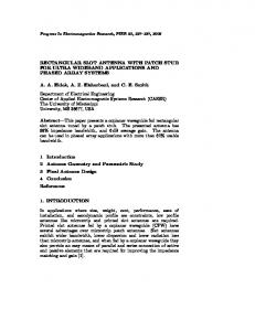
Figure 1: Rectangular Microstrip patch antenna at 4.3 GHz
Return Loss=
(7)
Calculation of Band Width(BW)
Simulated Results of RMPA Alone: Return loss
The BW of the MSA is inversely proportional to its quality factor Q and is given by [8]
B.W =
(8)
Design of Rectangular Microstrip patch Antenna The proposed antenna based on the Rectangular Microstrip Patch Antenna. The antenna is planar Rectangular Patch Antenna fed by Microstrip line on the PCB (print circuit board) FR4 substrate with dielectric constant 4.4, loss tangent 0.02 and 1.6mm of thickness (h). This antenna is design at frequency 4.3 GHz, width of microstrip is 3.009 mm for match impedance with 50 ohms of transmission line. The Rectangular Microstrip Patch Antenna is shown figure 1. The Essential parameters of the design are shown in table 1. TABLE1: Rectangular Specifications
Microstrip
Patch
Figure 2: Return loss S11 of Rectangular Microstrip patch antenna.
VSWR Graph
Antenna
Dielectric Constant (єr) Loss Tangent (tan ∂) Thickness (h) Operating Frequency Length (L) Width (W) Cut Width Cut Depth Path Length Width of Feed
Magnitude 4.4 0.02 1.6 4.3 20.75 34.35 5 8 22 3.009
Unit Mm GHz Mm Mm Mm Mm Mm Mm
Feed
Microstrip
-
Figure 3: VSWR of Rectangular Microstrip Patch Antenna
Design of Metamaterial Ground Plane
RMPA with Structure In
A new reduced size Rectangular Patch Antenna with two Narrow Orthogonal Crossed slits [5] is proposed. The orthogonal crossed slits are placed in ground plane in order to study its influence, and the results are compared with those of the antenna alone. The bandwidth [6] of proposed antenna has been improved 0.175 GHz. The length and width of ground plane are Length (L) = 30.2 mm and Width (W) = 44 mm.
Simulated Results of RMPA with Metamaterial Structure used for Single Band Operation: Return Loss
Slit are placed 10.05 mm from the larger wall of the patch and 9.65 mm from the smaller wall of patch. The thickness of slits is 0.5 mm. The required specifications of this design are shown in the Figure 4.
RMPA Loaded With Orthogonal Crossed Slits in Ground Plane
Figure 5: Return loss of Rectangular Microstrip patch antenna with Metamaterial structure
VSWR Graph
Figure 4: Rectangular Microstrip patch antenna with Metamaterial structure
Figure 6: VSWR of Rectangular Microstrip patch antenna with Metamaterial structure
Smith Chart
Antenna at frequencies 2.5GHz and 6.97GHz.Return loss is also reduced and reached up to the level of -19 dB. The simulated results of multiband operation, size reduction and Return loss reduction which are measured from IE3D simulation software are shown below.
Simulated Results of RMPA with Metamaterial Structure used for Double Band Operation: Return Loss
Figure 7: Smith chart of Rectangular Microstrip patch antenna with Metamaterial structure
Results and Discussions The Simulated Results of Rectangular Microstrip Patch Antenna alone and loaded with orthogonal crossed slits in Ground Plane are shown in figure 2 and figure 5. At 4.30 GHz frequency Simulated Rectangular Microstrip Patch Antenna alone exhibits the Return Loss of -12.32dB and Bandwidth improvement 58 MHz while when it is incorporated with orthogonal crossed slits Structure at the Ground Plane, it shows Return Loss around -15 dB and Bandwidth improvement 233MHz. This RMPA with narrow orthogonal crossed slits on the radiating patch resonates at frequencies 4.30 GHz and 2.50 GHz. This shows that when the slit is introduced in the radiating patch of the single band antenna then the resulting antenna is found for resonant frequency tends to lower side, which shows that the Antenna has compact in size as well as better performance in gain and bandwidth. The enhancement in Bandwidth near about 0.175GHz was achieved and Antenna was used for wideband applications. This design is also used for multiband operation. Figure 5 shows the return loss of RMPA with Metamaterial. Actually the return loss in that figure measured in frequency range between 2 to 3 GHz. If we increase that frequency range and operate it with a range of 2 to 7 GHz we achieve double band operation of
Figure 8: Return Loss of RMPA with Metamaterial structure for double band operation.
VSWR Graph
Figure 9: VSWR of RMPA with Metamaterial structure for double band operation.
Smith Chart
References
Figure 10: Smith Chart of RMPA with Metamaterial for double band operation.
Comparative Analysis
Simple RMPA RMPA with Metamateri al for Single band operation RMPA with Metamateri al for double band operation
Return Loss -12.32 dB -15 dB
-15 dBand 18.87 dB
VSWR 1.61 1.491
1.491 and 1.257
Band Width 58 MHz 233 MHz
Operating Frequency 4.3 GHz
233 MHz
2.5 GHz and 6.97 GHz
2.5 GHz
Conclusion It has been seen that, by using the properties of Metamaterial we can easily overcome the drawbacks of RMPA. Defected ground plane is used for improving the Bandwidth significantly which was the main drawback of Patch Antenna. The improvement in band width near about 0.175 GHz is achieved so that antenna can be used for wide band applications. It has also been proved that by using Metamaterial substrate we can easily reduce Return Loss also. This reduction of return loss indicates that only small amount of reflection waves were returned back to the source and most of the power will be radiated from the patch.
Acknowledgement The authors wish to thank their parents for supporting and motivating for this work
[1] V.G. Veselago, ―The electrodynamics of substances with simultaneously negative values of ε and μ‖, Sov. Phys. Uspekekhy. Vol.10, pp. 509-514, 1968 [2] K. R. Carver and J. W. Mink, ―Microstrip antenna technology‖, IEEE Trans. Antennas Propagation, vol. AP-29, no. 1, pp. 2–24, Jan. 1981 [3] Constantine A.Balanis, ―Antenna Theory and Design‖, John Wiley & Sons, Inc, 1997 [4] H.A. Majid, M.K.A. Rahim and T. Marsi, ―Microstrip Antenna gain enhancement using lefthanded metamaterial structure‖, progress in Electromagnetic Research M. Vol.8, 235-247, 2009 [5] Gian Chand, Ramesh Kumar, Monish Gupta and Dinesh Gupta, ―Improvement in Gain and Bandwidth of Rectangular Patch Loaded with Orthogonal Crossed slits‖ , IJECT, ISSN No. 22307109 Vol. 1, Issue 1, 2010 [6] Ahmad A.Sulaiman, Ahmad S. Nasaruddin, Mohd H.Jusoh, Nor H. Baba, Rabi’atun A. Awang and Mohd F. Ain, ―Bandwidth Enhancement in Patch Antenna by Metamaterial Substrate‖, Earopean Journal of Scientific Research ISSN I450-216X Vol. 44 No.3 pp. 493-501, 2010
Biographies ASHISH KUMAR received the B.Tech degree in Electronics and communication from U.P.T.U Lucknow Utter Pradesh in 2008. Currently he is persuing M.Tech in communication, control and networking from MITS College Gwalior, Bhopal, (M.P). His research interest includes Antenna and micro wave communication and their applications. Ashish kumar may be reached at
[email protected]. Mr. BIMAL GARG is currently associated with MITS, Gwalior as a Senior Faculty of Electronics and Communication Department. His research interest includes Antenna and micro wave communication, wireless communication and their applications. Bimal kumar may be reached at
[email protected]. RAHUL TIWARI received the B.E in 2008 from NRIITM, Gwalior and M.Tech. Degrees, from MITS, Gwalior in 2011. His research interest includes Antenna and micro wave communication and their applications. Rahul tiwari may be reached at
[email protected]. TILAK CHITRANSH received B.tech in 2008 from U.P.T.U Lucknow. At present he is persuing M.E in communication, control, and networking from MITS, Gwalior. His research interest includes Antenna and micro wave communication and their applications Tilak Chitransh may be reached at
[email protected].