The secondary windings are displaced from each other by 90 degrees. ..... components as meeting ISO/TS16949 requirements
W H I T E
PA P E R
Ramesh Ramamoorthy C2000™ Microcontroller Applications Engineer Texas Instruments
Reduce system costs with resolver-to-digital conversion implementation on C2000™ Delfino™ microcontrollers
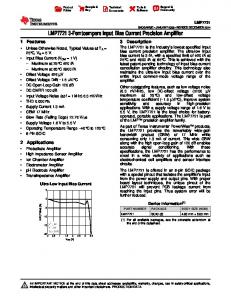
Introduction In a typical precision position servo control system, resolvers or encoders are used to provide shaft position feedback to the control unit. Resolvers are more robust and rugged than encoders, capable of withstanding reasonable amounts of environmental contamination and noise. While encoders’ outputs are in the form of pulse train, resolvers outputs are in the form of amplitude modulated sinusoidal signals that require additional processing to extract position information. This paper explains how TI’s C2000 Delfino microcontrollers can effectively process them to obtain the speed and position feedback with higher bit accuracy.
A resolver is a rotating transformer with the primary winding in rotor and two secondary windings in stator. The secondary windings are displaced from each other by 90 degrees. Hence, the primary flux linking the secondary windings will be proportional to the sine and the cosine of rotor position. If the primary winding is excited with a voltage ep = Emsin(ωct), then the voltages induced in the secondary windings (sine and cosine) are given by: esine = k. Emsin(ωct).sin(θ) ecosine = k. Emsin(ωct).cos(θ) where, ωc is the excitation frequency θ is the rotor position k is the transformation ratio between primary to secondary Powering up the primary winding in the rotor is another task. Slip rings, though capable, are not robust. That is why an auxiliary transformer is constructed at one end of the same stator and rotor concentrically, stator holding the primary winding and taking in excitation from external sources and the rotor holding the secondary winding to feed the primary of the resolver transformer as shown in Figure 1.
Figure 1: Resolver functional diagram
2
Texas Instruments
Design challenges with resolvers
Since the resolver output signals are trigonometrically related to each other, it is possible to extract rotor position information by a simple math as given by:
θ = tan-1(esine / ecosine) → 1
The fidelity of such a math is influenced by the quality of parameters in the right-hand side of this equation, which are the secondary voltages. They carry error footprints due to electrical phase shift, transformation ratio mismatch between secondaries and mechanical deviation from quadrature between secondaries. In addition to these native issues, external factors such as ground noise, gain mismatch and nonlinearity in the control circuit and carrier quality issues inject another degree of error. Hence care should be taken in the design of control hardware and software to reject as much of injected error as possible. Simple method The most simple and straight forward method is to implement equation 1. It makes sense to sample the values of the secondary signals at their peaks so as to ensure higher signal to noise ratio and use it in equation 1 as shown in Figure 2.
Figure 2: Simple implementation scheme
This simple method lacks in quality, though. Due to system noise, the estimated angle will have more jitters, which is why a filter is needed. Unfortunately, a filter will insert phase lag that will linearly vary with speed rendering itself unsuitable. This is why an observer is needed that not only filters the output jitters without any phase lag but also improves the accuracy of estimation in addition to providing a speed estimate of the rotor. Observer An observer is designed to track the parameter it is intended to observe with minimal error under all dynamic conditions. For this, it needs a reference and an estimate and takes corrective action based on observed error. It is possible to conceive an observer that can factor in the effect of load torque, to minimize response times, but then it will also need load inertia making it load dependent and hence it is not considered in this evaluation. In this particular case, the observer essentially becomes a PLL that needs a few functional blocks to perform certain tasks as shown in Figure 3.
Reduce system costs with resolver-to digital conversion implementation on C2000™ Delfino™ microcontrollers
September 2012
Texas Instruments 3
Signal cleansing - band pass filter For the observer to be robust, the parameters it takes as input should be as clean as possible. The sine and cosine feedbacks from the resolver can be potentially contaminated by ground noise, dynamic offset and gain variations of the feedback processing hardware before being read by the analog-to-digital converter (ADC). Most of this can be compensated by passing these signals through a band pass FIR filter, whose pass band is around the carrier frequency with a band width of at least twice the shaft speed. This limits the frequency spectrum of FIR output signals to Fc + Fb and Fc – Fb, effectively getting rid of dynamic dc drifts and most of the white noise from the feedback signals. This process adds additional bits of accuracy to these signals effectively increasing the fidelity of numerator and denominator of equation 1. Higher the sampling frequency and lower the bandwidth, higher is the accuracy. But practical considerations related to CPU loading sets the upper limit on sampling frequency and the order of FIR filter while the maximum rotor speed requirements sets the limit on bandwidth. When the order of FIR filter is lower, it is difficult to position the pass band precisely and hence the band width ends up being larger than needed. Within all these constraints, the accuracy is still improved. However, it is still not jitter-free, and a filter is needed.
Figure 3: Control block diagram
Decimation In order to utilize the full scale range of ADC and to improve signal to noise ratio, it makes sense to ignore the FIR outputs when they are not close to their cycle peaks. Therefore it is sufficient to perform FIR operation only for instances that give out cycle peaks, thereby leading to a natural decimation of either 2N:1 if one of the peaks is considered or N:1 if both peaks are considered. At a decimation of 2N:1, the sampling is synchronous to carrier frequency and hence will demodulate the signals to a frequency (Fb) corresponding to shaft speed, whereas, at a decimation of N:1, the demodulated signal will be at carrier frequency corresponding to its cycle peaks while holding the envelope of Fb. At N:1, additional logics are needed to differentiate between positive and negative carrier peaks. Half the decimation rate will give twice the number of samples per carrier cycle, but its choice is a trade off based on CPU capacity and system requirements. Error computation A straight method is to find arc tangent of the feedback signals and compare against observed value. Another popular method is to cross multiply the sine and cosine of estimated angle with that of the input signals and subtract one from the other, as mathematically given by: sin(θ-o| ) = sinθ.coso| – cosθ.sino| When θ ∼= o| , sin(θ-o| ) ~= θ-o|
In the second method, when the reference and estimate are far apart, the error is proportional to sine and becomes non linear unlike the first method. If the error angle lies within second or third quadrant, it may increase the response time for the second method. Under normal operating circumstances, such a huge error may not occur. Nevertheless, in this experiment, arc tangent method is used giving more credence to its linearity.
Reduce system costs with resolver-to digital conversion implementation on C2000™ Delfino™ microcontrollers
September 2012
4
Texas Instruments
Filter Even though the signals pass through a band pass filter, any noise within the base band can still sneak through and distort the end result. A simple first order filter can minimize its impact. Since the sourcing signal is dynamically varying (ramp) as compared to the error signal (DC), filtering the error signal can reduce the noise impact without inserting any phase shift or distortion. Band pass delay compensation FIR filters’ outputs are delayed proportional to the number of taps regardless of input frequency. If there are N samples of carrier and N+1 taps for the FIR filter, then the delay is given by N.Ts/2, where Ts is the sampling time. Since N samples are spread over one carrier cycle, there will be a half carrier cycle delay. This can be compensated based on the current speed estimate of the rotor as shown in the block diagram. Tuning the loop The open loop transfer function of the system is given as follows:
Its root locus plot is as shown in Figure 4.
wf
wpi
Figure 4: Root locus plot of the resolver plant
Depending on the level of noise filtering needed, ωf can be chosen. For loop stability, ωpi will have to be lesser than ωf. The closed loop transfer function is given by:
The steady state error of this observer is proportional to rotor acceleration. By choosing a higher value for kp, this error can be minimized. By choosing right values of Kp, wz, wp1, δ and wn, the transient response and filtering level can be tuned to preferred levels.
Reduce system costs with resolver-to digital conversion implementation on C2000™ Delfino™ microcontrollers
September 2012
Texas Instruments 5
Experimental set up
To evaluate the overall performance of resolver interface including hardware and software, an absolute encoder is used as reference. Hence the test bench included a motor, an absolute encoder and a resolver. Hardware Interface The hardware schematic of the resolver interface is as shown in Figure 5. The primary winding of resolver is excited with a sine voltage of 10Vp-p at 10KHz. It is generated using sinusoidal PWM out of a timer and is filtered in two stages to get a visibly clean sine wave free of harmonics. The signal shown as PWM_dither is connected to GND through a GPIO. The feedbacks from resolver are trimmed to fit within C28’s ADC range. This stage can potentially insert errors due to drift in offset / gain, though some of it can be taken care of by FIR filter. Hence proper care should be given in the choice of components.
Figure 5: Hardware schematic diagram
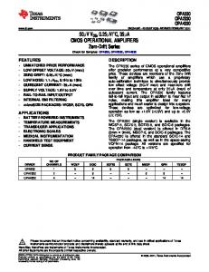
Software Interface The feedbacks are sampled at 160KHz (8 times oversampling), getting 16 samples per carrier sine wave. After an initial offset compensation, they are passed through the control block diagram shown in Figure 3 and angular estimates are obtained. On the Delfino MCU (TMS320F28335), it is implemented on CPU. The carrier wave is also updated at this rate and the instance of ADC sampling is positioned to capture the modulated feedbacks from the resolver at their peaks. Test procedure The motor is disconnected and the rotor is kept static during any given test. Position estimates from the resolver and absolute encoder are obtained and compared. For any given position, the absolute encoder will provide a single unique value, whereas the resolver will provide a range of values fractionally varying from each other. The average value of resolver output is compared against the encoder output to get mean error, and the worst case deviation of the encoder output against its mean is calculated to get the system noise or digitizing error. If this error is lower, the resolution and performance will be higher. This test is repeated for various rotor positions over a complete rotational cycle, and the results are plotted as shown in Figure 6 for Delfino MCUs.
Reduce system costs with resolver-to digital conversion implementation on C2000™ Delfino™ microcontrollers
September 2012
6
Texas Instruments
Fig. 6
(a) System error with Delfino
(b) Digitising error with Delfino
Table 1 Worst case test results Device Delfino- 28335
System Error (Analog Front End)
Digitizing Error (Noise)
Mean Abs Error (arc min)
Error Deviation (arc min)
Min
Max
Min
Max
2.63672
28.59192
1.40076
1.89514
ENOB 13.476
It may be noted that the max mean error is about 25 arc minutes. This needs a correction to handle the error introduced during initialization of encoder. The encoder output was manually reset to zero when the resolver output was about zero, before starting the tests, just to set a datum line between resolver and encoder. But this has pushed the error values to stay positive at all positions. If the datum was set such that the error swung equally positive and negative over the whole cycle, then the max error would have been only about 12 arc minutes. It must be noted that this error is the cumulative sum of all errors in the resolver system that includes mechanical, electrical, electronics, quantization and numerical round off errors. The measured resolution is greater than 13 bits with a Delfino device. Additional bits of data can be extracted but they may not represent the factual angle because of their inconsistency, resulting in as many LSBs of error.
wf wpi
wf
wf
wpi
wpi
Figure 7: Root locus analysis of locating open loop zero against open loop pole.
Reduce system costs with resolver-to digital conversion implementation on C2000™ Delfino™ microcontrollers
September 2012
Texas Instruments 7
Impact of placement of open loop parameters The tunable parameters in the open loop system are loop gain (Kp), zero (ωpi) and pole (ωf). Given the spread of poles and zeros here, ωpi will have to be lesser than ωf for closed loop stability. In general, if any closed loop pole is closer to the origin, it will slow down the system. If ωpi is close to ωf as in Fig. 7(a), then the open loop poles at origin will slightly move to the left splitting into a complex pair essentially staying close to the origin for all Kp. On the other hand, if ωpi is close to zero as in fig. 7(b), then a dominant closed loop pole will occur close to origin for all Kp. Hence an intermediate value is needed as shown in fig. 7(c). Along with a suitable choice of Kp, good performance can be obtained. When Kp is low, the closed loop poles are close to the origin and the filtering effect is dominant. This is verified by the experiments also. However, some rogue samples show up occasionally impairing the digitizing error.
Table 2 Worst case CLA/CPU loading* by closed loop algorithm Device
With Filter Type
Clock Cycles
Math Type
Delfino- 28335
16th order FIR
285
FPU
*Test Conditions: Compiler v6.1.0, code optimization -1 Safety aspects It is important to check the sanity of sine and cosine feedbacks, as the fidelity of entire system is based on this. It is possible that one of the signals may have deteriorated or disconnected and the control system should be cognizant of such an occurence. A simple trigonometry can be performed on the feedback to verify if sin2θ’+ cos2θ’ = a constant. A small variation may be allowed to accommodate the impact of noise and offset. Similarly, the loop error also needs to be monitored. Under normal conditions, it should be close to zero. Realistic motor drives have definite inertia and hence abnormal speed changes are unlikely. Any large angular error is an indication of loop falling apart which needs to be identified.
Conclusion
A comprehensive evaluation of resolver to digital conversion is done using Delfino devices and the measured accuracy is 13 bits with a 10KHz carrier wave. This functionality can be implemented as a standalone solution on a low cost low pin out device or as part of a larger motor control system on a higher pin out device. Tradeoffs can be made in sampling frequency to adjust the CPU loading to meet the requirements.
Important Notice: The products and services of Texas Instruments Incorporated and its subsidiaries described herein are sold subject to TI’s standard terms and conditions of sale. Customers are advised to obtain the most current and complete information about TI products and services before placing orders. TI assumes no liability for applications assistance, customer’s applications or product designs, software performance, or infringement of patents. The publication of information regarding any other company’s products or services does not constitute TI’s approval, warranty or endorsement thereof.
The platform bar, C2000 and Delfino are trademarks of Texas Instruments. All other trademarks are the property of their respective owners. © 2012 Texas Instruments Incorporated
E010208
SPRY212
IMPORTANT NOTICE Texas Instruments Incorporated and its subsidiaries (TI) reserve the right to make corrections, enhancements, improvements and other changes to its semiconductor products and services per JESD46, latest issue, and to discontinue any product or service per JESD48, latest issue. Buyers should obtain the latest relevant information before placing orders and should verify that such information is current and complete. All semiconductor products (also referred to herein as “components”) are sold subject to TI’s terms and conditions of sale supplied at the time of order acknowledgment. TI warrants performance of its components to the specifications applicable at the time of sale, in accordance with the warranty in TI’s terms and conditions of sale of semiconductor products. Testing and other quality control techniques are used to the extent TI deems necessary to support this warranty. Except where mandated by applicable law, testing of all parameters of each component is not necessarily performed. TI assumes no liability for applications assistance or the design of Buyers’ products. Buyers are responsible for their products and applications using TI components. To minimize the risks associated with Buyers’ products and applications, Buyers should provide adequate design and operating safeguards. TI does not warrant or represent that any license, either express or implied, is granted under any patent right, copyright, mask work right, or other intellectual property right relating to any combination, machine, or process in which TI components or services are used. Information published by TI regarding third-party products or services does not constitute a license to use such products or services or a warranty or endorsement thereof. Use of such information may require a license from a third party under the patents or other intellectual property of the third party, or a license from TI under the patents or other intellectual property of TI. Reproduction of significant portions of TI information in TI data books or data sheets is permissible only if reproduction is without alteration and is accompanied by all associated warranties, conditions, limitations, and notices. TI is not responsible or liable for such altered documentation. Information of third parties may be subject to additional restrictions. Resale of TI components or services with statements different from or beyond the parameters stated by TI for that component or service voids all express and any implied warranties for the associated TI component or service and is an unfair and deceptive business practice. TI is not responsible or liable for any such statements. Buyer acknowledges and agrees that it is solely responsible for compliance with all legal, regulatory and safety-related requirements concerning its products, and any use of TI components in its applications, notwithstanding any applications-related information or support that may be provided by TI. Buyer represents and agrees that it has all the necessary expertise to create and implement safeguards which anticipate dangerous consequences of failures, monitor failures and their consequences, lessen the likelihood of failures that might cause harm and take appropriate remedial actions. Buyer will fully indemnify TI and its representatives against any damages arising out of the use of any TI components in safety-critical applications. In some cases, TI components may be promoted specifically to facilitate safety-related applications. With such components, TI’s goal is to help enable customers to design and create their own end-product solutions that meet applicable functional safety standards and requirements. Nonetheless, such components are subject to these terms. No TI components are authorized for use in FDA Class III (or similar life-critical medical equipment) unless authorized officers of the parties have executed a special agreement specifically governing such use. Only those TI components which TI has specifically designated as military grade or “enhanced plastic” are designed and intended for use in military/aerospace applications or environments. Buyer acknowledges and agrees that any military or aerospace use of TI components which have not been so designated is solely at the Buyer's risk, and that Buyer is solely responsible for compliance with all legal and regulatory requirements in connection with such use. TI has specifically designated certain components which meet ISO/TS16949 requirements, mainly for automotive use. Components which have not been so designated are neither designed nor intended for automotive use; and TI will not be responsible for any failure of such components to meet such requirements. Products
Applications
Audio
www.ti.com/audio
Automotive and Transportation
www.ti.com/automotive
Amplifiers
amplifier.ti.com
Communications and Telecom
www.ti.com/communications
Data Converters
dataconverter.ti.com
Computers and Peripherals
www.ti.com/computers
DLP® Products
www.dlp.com
Consumer Electronics
www.ti.com/consumer-apps
DSP
dsp.ti.com
Energy and Lighting
www.ti.com/energy
Clocks and Timers
www.ti.com/clocks
Industrial
www.ti.com/industrial
Interface
interface.ti.com
Medical
www.ti.com/medical
Logic
logic.ti.com
Security
www.ti.com/security
Power Mgmt
power.ti.com
Space, Avionics and Defense
www.ti.com/space-avionics-defense
Microcontrollers
microcontroller.ti.com
Video and Imaging
www.ti.com/video
RFID
www.ti-rfid.com
OMAP Applications Processors
www.ti.com/omap
TI E2E Community
e2e.ti.com
Wireless Connectivity
www.ti.com/wirelessconnectivity Mailing Address: Texas Instruments, Post Office Box 655303, Dallas, Texas 75265 Copyright © 2012, Texas Instruments Incorporated