REDUCED ORDER UNKNOWN INPUT KALMAN FILTER: APPLICATION FOR VEHICLE LATERAL CONTROL D. Koenig* and S. Mammar† *Laboratoire d'Automatique de Grenoble (UMR CNRS-INPG-UJF) BP 46, 38402 SAINT MARTIN D'HERES CEDEX, FRANCE † LSC-CNRS FRE-2494, Université d’Evry 40 rue du Pelvoux 91020 Evry Cedex, FRANCE
[email protected],
[email protected] Abstract A new optimal filtering formula is derived for stochastic linear systems with structured unknown inputs. The main idea consists in finding a robust sub-system of unknown inputs in which the dynamical and output noises are uncorrelated. Thereby the problem is reduced to the sub-state estimation of an unknown inputs-free reduced system, which can be easily dealt with following the well-known Kalman filter theory. After a change of basis, we can then rebuild the state of the original system. The method developed is applied to the lateral control of a vehicle.
1.
INTRODUCTION
The state estimation problem for unknown inputs deterministic systems using full-order or reduced-order observers is being increasingly discussed in both research and applications. However, few approaches have been developed for unknown inputs stochastic systems. The most common approach assumed that all system parameters, noise covariance’s and inputs are known. In practice, there are many situations in which this assumption is not valid. Indeed, the standard Kalman filtering technique may fail in the presence of parametric uncertainties, noise covariance uncertainties or unmeasurable inputs. To solve this problem, Kitanadis [8] has extended the Kalman filter by minimizing the trace of the state error covariance matrix under an algebraic constraint. Darouach et al [2], have proposed an approach for the design of unknown input decoupled optimal filter by transforming a standard system with unknown input into a singular system without unknown input, however they only considered time invariant systems. Hou and Patton [4] also made a contribution in the design of full-order unknown input decoupled optimal Kalman filter for time-varying systems using the recently developed disturbance decoupling technique [5]. Nevertheless, when real time computational limitations are needed, a reduced-order Unknown Input Kalman Filter (UIKF) may be an attractive solution. Recently, Keller and Darouach [7] have proposed a solution to estimate a part of the state vector for unknown input linear time-invariant system. Using another new unknown-input decoupling technique of [9] and applying the standard Kalman filter approach, this paper shows how a reduced-order UIKF can be solved even if the distribution matrix is time varying and unknown-input term appear in state and measurement equations. Three main transformations are used to remove the unknown input term. Section 2 presents briefly the system description and describes the solution to the optimal filtering problem. In
section 3, an example is presented concerning vehicle lateral control. A state feedback is first designed which ensures robust decay rate, minimum L2 gain attenuation and limitation on control effort. Afterwards the obtained state feedback estimation controller is completed with a reduced order unknown input Kalman filter. From automatic control concept view point, the controller for automatic steering must deal with multiple stability and performance objectives.
2.
ROBUST STATE ESTIMATION
Consider the following linear time-varying discrete stochastic system with structured unknown input: x k +1 = A k x k + B k u k + E1k d k + G k w k (1)
y = Ck x k + E2k dk + vk
(2)
k
where x k ∈ ℜ n (a real n-vector), u k ∈ ℜ e , d k ∈ ℜ p1 and
y ∈ ℜ m1 are the state, deterministic control (assumed k
known), unknown input and output vectors, respectively. The statistical properties of x 0 , w k and v k are described in assumption A1 below [4]. All coefficient matrices in (1)-(2) are known real matrices of appropriate dimensions. No particular assumption is made on these matrices except for a necessary rank condition on Ak, Ck, E1k and E2k, which is illustrated in assumption A2 below [4]. A1: The noises sequences wk and vk are assumed to have certain statistical properties, corresponding to a zero mean uncorrelated random sequences with 0 w Q (3) ×δ E k w'j v'j = k 0 R k kj v k where the symmetric matrix Qk (Rk) is called the intensity or covariance matrix of wk (vk) i, (4) Q k = Q'k ≥ 0 , R k = R'k > 0 and δ kj is the Kronecker delta which is unity for k = j. The initial state x 0 is assumed to be uncorrelated with the white noise processes w k and v k . We assume that the initial condition x 0 is a gaussian random variable with
{ }
{
}
E x 0 = x 0 ; E ( x 0 − x 0 )( x 0 − x 0 )' = Px ( 0 0 )
i
(.)’ denotes the transpose of the matrices (.) E{.} denotes the mean value of the sequence {.}
(5)
Second transformation As the matrix E12 is of full column rank, it is always possible to transform E12 into the following form: ) T1 0 E 12 k = Tk E 12 k = + k E 12 k = ( n − p )×p (13) I E p 12 k
A2: Rank condition on Ak, Ck, E1k and E2k
zI − A k rank n Ck E rank 2 k 0
− E1 k = n + p1 , ∀z ∈ C, z ≥ 1 (6) E 2 k
C k E1 k − rank[E 2 k ] = p1 with m1 > p1 (7) E 2 k
n ×(n − p ) ' where T' 1 k = Ker E 12 k ∈ ℜ
Assumptions A1 are well-known in the Kalman filter theory. Assumptions A2 has been proved to be necessary for the technique existence of an unknown-input decoupled observer, developed in [5]. As a linear filter has the same structure as an observer, assumptions A2 should also be necessary for designing a unknown-input decoupled filter. The aim of this paper is to derive a reduced order unknowninput decoupled optimal filter for the system (1)-(2). The optimum is determined in the sense of linear minimum variance estimation (see [1] and [6] for the detailed definition and related concepts). Step 1: The filter is derived by transforming to a basis where a subspace of state and output vector are decoupled from the unknown inputs. Step 2: Using the traditional Kalman filter, we deduce the linear optimal sub-state estimation and we return to the original basis in order to obtain the linear optimal full state estimation of (1)-(2).
2.1
Procedure design
Step 1: Consider system (1)-(2) that satisfies assumptions A1 and A2. First transformation As m1 ≥ p1 it exists an orthogonal matrix U and a nonsingular matrix V such as 0r×p Ir E 2 k = U'k × (8) × Vk 0 0 m× p m×r
with p = p1-r and m = m1-r Substituting relation (8) in (2) we obtain x k +1 = A m k x k + B m k u m k + E12 k d 2 k + G m k w m k y y
(9)
dk
= C d k x k + d1k + v d k
(10)
mk
= Cm k x k + v m k
(11)
where y
r
dk
∈ ℜ represent the measure disturb, y
mk
∈ℜ
is an orthonormal basis for the null space of E'12 k and
(
+ ' E 12 k = E 12 k X E 12 k
)
−1
E'12 k X with X=I
since E12k is of full column rank T × T' = I 1k
1k
n −p
(15)
ii
(16)
Therefore, the matrix Tk is a non-singular matrix and its inverse is: Tk_ 1 = T' E 12 k (17) 1 k The design of a reduced order unknown inputs decoupled filter for the system (9) - (11) is then equivalent to the design of a full order unknown inputs decoupled filter for the following sub-system: ) ) ) ) ) ) x1k+1 = A11k x1k + A12k x 2 k + B1k u m k + T1k Gm k w mk (18) ) ) ) ) ) ) + x2k+1 = A21k x1k + A22k x2k + B2k uk + d2k + E12 k Gmk wk (19) ) ) ) ) (20) y = C1 k x 1 k + C 2 k x 2 k + v m k mk ) x ) ) where: x k = Tk x k = ) 1 k , x 1 k ∈ ℜ n − p x 2 k ) In (19) the sub-vector x 2 is directly involved in the unknown ) inputs d (i.e. x 2 can be considered as an unknown inputs). So, using only the relation’s (18) and (20) we find the subsystem without unknown input. Third transformation ) By assumption A3, the matrix C 2 k = C m k E 12 k is of full column rank then we can make the same transformation as (13), we obtain: ) T3 ) 0 T2 k C 2 k = ) +k C 2 k = (m − p )×p I C p 2k where
m
the measure without disturb and d 2 k ∈ ℜ p the new unknown input disturbance, In this system the unknown input term in measurement equation (11) does not appear. Assumption A2 should also be equivalent to the following assumption: A3: Rank condition on A m k , C m k and E12 k rank zInC−mA m k −E012 k =n + p, ∀z∈C, z ≥1 k
(14)
−1 ) ) ) ) m×( m − p ) )' T' , C 2+ k = C'2 k C 2 k C'2 k 3 k = Ker C 2 k ∈ ℜ Pre-multiplying both sides of the measurement equation (20) by T2k, we get: ) ) ) y = T3 k y = T3 k C1 k x 1 k + T3 k v m k (22) mk k )+ ) ) ) x 2 k = C 2 k ( y − C1 k x 1 k − v m k ) (23) mk
and hence, substituting (23) into (18), we obtain the ) following sub-system, who is insensitive to d , d 2 and x 2
(12) ii
(.)
(.)+ denotes the Moore Penrose pseudo-inverse of matrix
) ) x 1 k +1 = A k x 1 k + B k u k + G k w k ) ) y = C k x 1k + v k
(24) (25)
k
u m k vmk ) where: u k = , wk = , y k = T3 k y m k y w m k m k ) ) ) ) v k = T3 k v m k , A k = A 11 k − A 12 k C 2+ k C1 k ) ) ) ) ) B k = B1 k A 12 k C 2+ k , G k = − A 12 k C 2+ k T1 k G m k ) C k = T3 k C1 k (27) The design of a reduced order unknown input decoupled filter for the system (9) - (11) is then equivalent to the design of an unknown input decoupled filter for the system (24)-(25) where any unknown input term appear.
( ]
[
[
)
]
Assumption A2 and A3 should also be equivalent to the following assumption: A4: Rank condition on A k and Ck
purposes, existence and stability of the filter are provided in [10].
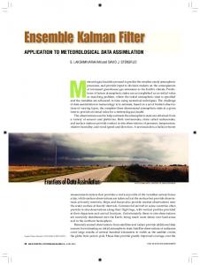
3. EXAMPLE To illustrate the design procedure of the reduced order unknown inputs Kalman filter, we consider the lateral control of a vehicle. The vehicle is unstable, non-linear and has noisy sensors. First we linearize the mathematical model to obtain a linear unstable system (35) - (36). An integral action (26) is added on the lateral displacement in order to ensure zero steady state error against constant perturbation (road curvature). Thus a state estimation feedback controller is synthesised on the augmented plant using a LMI method, in order to ensure robust stability against parameter variations and constraints on both lateral acceleration and yaw angle (Figure 1). In addition, the synthesized control law is tested for several vehicle maneuvers such as ♦ transition from manual to automatic steering, ♦ lane keeping. y d : lateral distance desired
zI − A k (28) rank = n − p, ∀z ∈ C, z ≥ 1 Ck Step 2: The process and sensor noises w , v are correlated, we can avoid this using a preliminary transformation [1]: E v k w 'j = S 'k × δ kj (29)
k
A k = A k − G k S k R k C k , B k = B k −1
Gk
(34)
u Gk = , u k = ) k y k More details on statistical noise properties are given in [10]. We have obtain the unknown-inputs-free reduced system (32) - (33) with uncorrelated process and sensor noises. We can ) also estimate the sub-state (x1 ) from the standard Kalman filter, since all system parameters, noise covariance’s and input are known. −1 G k Sk R k
One can conclude that the proposed (n-p) dimensional filter ) gives an unbiased minimum variance estimate of x 1 and provides the optimal linear estimate xˆ . If all noises are Gaussian it provides the optimal estimator. Implementation
Reduced Order Unknown Inputs Kalman Filter
K2 Full state estimation
Figure 1: Lateral control of a vehicle system
3.1
−1
where
vehicle system
Feedback gain K
0 (30)
w k = w k − Sk R k v k (31) in (24), leads us directly to search the equivalent model with uncorrelated process and sensor noise: ) ) x 1 k +1 = A k x 1 k + B k u k + G k w k (32) ) ) y = C k x 1k + v k (33)
K1
1p
∆ ψ y= measurements ys
integral action
{ }
where S 'k = T3 k U 2 k R k U '2 k T3 k U 2 k R k U 1' k Set the following new variable
u
Vehicle modelling
The well used fourth order linear lateral model for the vehicle is obtained by projection of the kinematic equations on the longitudinal axis [11]. β& a 11 a 12 0 0 β b1 0 r& = a 21 a 22 0 0 r + b 2 δ + 0 ρ (35) & 0 ∆Ψ 1 0 0 ∆ψ 0 − v l s v 0 y s 0 0 y& s v β y 0 0 1 0 1 r = y 2 0 0 0 1 ∆ψ ys where:
a 11 =
(36)
(c .l − c .l ) −(c r + c f ) , a 12 = −1 + r r 2f f , m.v m.v
(c .l2 +c .l2) (c r .l r − c f .l f ) c a 22 =− r r f f , b1 = f , , J . v J m.v cflf . In addition m is the vehicle mass, ls is the b2 = J distance from the vehicle centre of gravity (CG) to the sensor, lr and lf are respectively the distance from the rear and the front axle to the centre gravity, cr and cf are the cornering stiffness, and J is the vehicle inertia. a 21 =
The state vector components are the sideslip angle β, the yaw rate r, the angle between the centreline of the car and the tangent to the guideline ∆ψ and ys is the lateral displacement at the sensor location. The variable which is usually used to reflect driver and passengers comfort is the lateral acceleration defined by a l ( t ) = v. β& + r (37)
(
)
According to framework (1)-(2) the control input (i.e., u = δ )
is the steering angle δ, and the unknown inputs d, correspond to the trajectory to be followed, which is described by the road curvature ρ. We will also assume that a change in road curvature is equivalent to an unknown input on the system. In the following, it will be assumed that only ∆ψ and ys are measured by a video camera i.e., y' = [∆ψ y s ] and then available for use in state estimation. In addition, the control synthesis and simulations will be conducted for a medium class vehicle. Three kinds of plant uncertainties have to be considered : mass variations ( [1350,1650][kg]) adhesion variations ([0.7, 1] of their nominal values (cr0, cf0)) and velocity variations ( [10,30][m/s]). The cornering stiffness and speed variations alter significantly the parameter values of the state space model. Obviously, the others model data are maintained constant lf = 1.15 [m], lr = 1.51[m], ls =4[m] and J = 2750[kg.m2]. The nominal value of cf and cr are cf0 = 50400 [N.rad-1] and cr0 = 33600[N.rad-1].
3.2
Vehicle modelling
As the mass variation in this case is not significant, the state feedback controller is needed to be robust to only speed and cornering stiffness variations. In order to obtain the linear fractional transformation (LFT) model of the vehicle, each of the uncertain term is written in the following form c r = c r 0 (1 + σ r δ r ), δ r ≤ 1 c f = c f 0 (1 + σ f δ f ),
δf ≤ 1
v = v 0 (1 + σ v δ v ),
δv ≤1
(38)
where c r 0 ,c f 0 ,v 0 are the nominal values, δ r ,δ f ,δ v are the uncertainty, and σ r ,σ f ,σ v are measures of the relative uncertainty size. The system is first augmented with the integral action on the output ys, and is then transformed into a continuous LFT model. The discrete LFT model is obtain from the continuous LFT model with uncertainty of the following form : (39) ∆ (t ) = diag δ r I 2 δ f I 2 δ v I 5 , ∆(t ) ≤ 1
{
}
where the output to be regulated z(t) are the lateral displacement and the lateral acceleration.
3.3
Design objectives
For automatic steering, the design performance objectives can be defined in terms of maximal lateral displacement from the guideline and lateral acceleration peak value. During lane
keeping maneuver, the purpose of the steering controller is to keep the lateral displacement as close as possible to the origin. In fact the lateral displacement is influenced by both the road curvature (external disturbance input to the system) and the control input (steering angle). The controller has then to counteract the effect of road curvature. However, the lateral displacement may not exceed 5[cm] in the transition phase and must be zeros in steady state. So an integral action is added on the lateral displacement. On other hand the lateral acceleration has to be limited to 2[m.s-2] (0.2g) for passengers comfort, with a maximal overshot of (0.1g) from this value. These objectives are limited by the constraint of the steering angle value, which may not exceed 5 [deg] at speed range considered here.
3.4
Control Synthesis
Controller synthesis is conducted on the nominal system which corresponds to v = 20 [m.s-1], m = 1550 [Kg] and µ = 1. The state feedback gain K is obtained using the LMI conditions given in [3] which include minimum decay rate α, L2 gain attenuation γ and constraint on control input umax. They are solved with the package [] and the following parameters are achieved : x 0 = [± 0.01 ± 0.01 ± 0.01 ± 0.4 0]T = 0.98 α u max = 0.07[rd] ≅ 4° = 0.1 γ σ r = σ f = 0.3 ; σ v = 0.5
and yields to the state feedback K = [-0.6543 -0.1105 -1.1228 -0.1334 0.0605] To synthesise the UIKF we use only the four first state since the fifth state is calculated from ys and yd. So the continuous linear unstable system (35)-(36) can be described by the following nominal (v=20 [m.s-1], m = 1550 [Kg]) linear time invariant system and the sample time is Te=0.01s. The measurement noises are due to the video sensor while the state noise is due to the actuator. The first and the second statistic properties of these noises are chosen after camera calibration and several measurements trails. Therefore, these noises may be assumed to be zero mean gaussian noise processes, uncorrelated with each other and with x 0 and d 0 . For brevity, we present only the UIKF results for the nominal linear time invariant system. If the forward speed is assumed to be measured we can used the implementation of the reduced order UIKF in real time. The matrices are then scheduled according to speed.
3.5
Simulation tests
The synthesized control law is now tested for several common vehicle maneuvers such as transition from manual to automatic steering, and lane keeping; These maneuvers are conducted for the nominal system and the four vertex systems ♦ system (S0) for the nominal mass, road adhesion and speed
♦ system (S1) for maximal mass and minimal adhesion and minimal speed ♦ system (S2) for minimal mass and maximal adhesion and minimal speed ♦ system (S3) for maximal mass and minimal adhesion and maximal speed ♦ system (S4) for minimal mass and maximal adhesion and maximal speed. Results for each case (Si) are given in the same figure.
road road road road
3.5.1 Transition from manual to automatic steering In this first maneuver, the vehicle is assumed to be on straight road at a lateral distance of 0.4 [m] from the centerline when the automatic steering is setup. In this case the speed is assumed to be not measured, so the steady state UIKF matrix is used. This allows to illustrate the influence of parameter variations (speed, mass, cornering stiffness) of control and estimate. The vehicle enters at time t=5[s] a curve with curvature 1/500[m-1] at nominal speed of 20[m.s-1] (system S0), this means that the steady lateral acceleration is equal to ( − v 2 .ρ = 0.08[ g ] ). For the minimal speed of 10 [m.s-1] (systems S1 and S2) the road curvature is chosen to be equal to 1/200[m-1]. Finally for the maximum speed of 30[m.s-1] (systems S3 and S4) the curvature is decreased to 1/1000[m-1]. These curvature are the maximal allowed safety curvature at these speed. Figure shows the results obtained for the lateral displacement. One can see that in the first phase of the maneuver, the reduced order unknown input Kalman filter and the usual Kalman filters performs rather the same estimate of the lateral displacement measurement y2. However when the vehicle enters a curve, obviously the usual Kalman filter fails while reduced UIKF estimate is robust against this road curvature unknown input. The response is well damped and the center of the lane is reached in less than 2[s]. When the speed is increased to 30 [m/s] and the road adhesion is reduced to 0.8 of its nominal value (wet road), the responses become more oscillatory but are still acceptable. The control effort is limited in all cases as it can be seen from figure 3 and is less than the prescribed limit of 5 [deg].
3.5.2
Lane keeping
For this maneuver, the forward speed is assumed to be measured. So, we can use the real-time version of the presented UIKF to implement and to investigate its performances. The matrices are then scheduled according to speed variations. The controller performance are investigated on a stretch of a roadway where the vehicle must enter a curve enters at time t=5[s] and exits a curve at time t=10[s]. For this maneuver, the vehicle enters a curve with curvature 1/500[m-1] at nominal speed of 20[m.s-1] (system S0). For the minimal speed of 10 [m.s-1] (systems S1 and S2) the road curvature is chosen to be equal to 1/200[m-1]. Finally for the maximum speed of 30[m.s-1] (systems S3 and S4) the curvature is decreased to 1/1000[m-1]. These curvature are the maximal allowed safety curvature at these speed.
Figure 2: Lateral displacement for transition from manual to automatic steering : measurement (y2) and estimates (xˆ4 )
Figure 3: Steering angle (control input) Figures 4, 5, and 6 show the responses for the five systems. One can see that the lateral offset is less than 5[cm] during the transition phase and tends to zero in steady state when the speed is less than 30[m.s-1] (systems S0, S1 and S2). When the speed is equal to 30[m.s-1] (systems S3 and S4), the responses are more oscillatory. They are still acceptable when the road adhesion is at maximal value (system S4), however responses for system S3 indicate that the minimal road adhesion value is incompatible with the considered speed. The lateral acceleration is shown on figure 6 indicates at nominal speed S0 (low speed S1 and S2) a steady acceleration limited to 0.08 [g] (0.05 [g]). These values correspond
exactly to v2ρ. For systems at high speed (S3 and S4) the acceleration increases to 0.2[g] but it is always less at the allowed overshot (0.3[g]).
Figure 6: Lateral acceleration for lane keeping
Figure 1: Lateral displacement for lane keeping
input. Hence, the problem of filtering is reduced to a mere problem of Kalman filtering. The UIKF synthesis methodology has been applied to automatic steering of a vehicle. The combination of robust multi-objectives state feedback estimation with the reduced order UIKF has proved to be efficient
5.
Figure 5: Steering angle for lane keeping (control input)
4. CONCLUSION This new approach is a generalisation of the conventional Kalman filter for a linear varying stochastic multivariable system in presence of unknown input terms at states and measurements equations. The state x can be estimated completely independently of the unknown inputs d and the np dimensional filter gives an unbiased minimum variance ) estimate of x1 . We have shown, by three regular transformations, (numerically stable) how to reduce the stochastic model with unknown input into a robust sub-system without unknown
REFERENCES
[1] Anderson B. D. O, and Moore J. B, "Optimal Filtering" Englewood Cliffs, NJ: Prentice-Hall, 1979. [2] Darouach M, Zasadzinski M, Bassong-Onana A and Nowakowski S, "Kalman filtering with unknown inputs via optimal state estimation of singular systems," INT. J. Systems SCI., vol. 26, no. 10, pp. 2015-2028, 1995. [3] Dussy S and Ghaoui L. El, "Multiobjective Robust Measurement-Scheduling for Discrete-Time Systems: an LMI Approach", in Proc. 3rd IFAC Conference on System Structure and Control, 1997. [4] Hou M and Patton R.J, "Optimal filtering for Systems with Unknown Inputs", IEEE Transactions on Automatic Control., vol. AC-43, no. 3, pp. 445-449, 1998. [5] Hou M. and Müller P.C, "Disturbance decoupled observer design : A unified viewpoint", IEEE Transactions on Automatic Control., vol. AC-39, pp. 1338-1341, 1994. [6] Kailath T, "Linear systems", Prentice Hall Information and System Sciences Series, 1980. [7] Keller J.Y and Darouach M, "Reduced-order Kalman Filter with Unknown Inputs", Automatica, vol 34, no. 11, pp. 14631468, 1998. [8] Kitanidis P.K, "Unbiased minimum-variance linear state estimation", Automatica, 23, pp. 775-778, 1987. [9] Koenig D and Patton R.J, "New Design of Robust Kalman Filters for Fault Detection and Isolation", 14th World Congress IFAC, Beijing P.R. China, July 5-9, 1999. [10] Koenig D and Mammar, S., "Reduced Order Unknown Input Kalman Filter with Application to Vehicle Robust Lateral Control, Submitted, 2002. [11] Mammar S., "Robust Automatic Steering of a Vehicle : An LMI Approach", 8th IFAC Symposium on Transportation Systems, (Ghania), pp 391-396, 1997.