cause of EMI. Common ground impedance converts ground currents to a common voltage, which acts as a potential source of EM1 to push currents around the.
REDUCING EM1 IN CRT BASED DISPLAY SYSTEMS THROUGH GROUNDING AND SHIELDING Vinod Karar, Surender Singh Sain?, MSN Srinivas and Vipan Kumar Central Scientific Instruments Organisation, Sector 30, Chandigarh - 160030 (India) ABSTRACT - The effect of the interference on the display can be in the forms of momentary flicker o r jitter, continuous disturbance in the display, loss of genlocking, blanking of display o r damage due to spikes. Mainly the grounding problems are due to common mode coupling, wbich can be reduced by ground impendence reduction, ground loop reduction. The need of shielding arises in display systems as noise source couple into wires by nearby high current, high bandwidth amplifier, and induction o r by capacitive coupling because of nearby power lines, computer equipments, motorized equipments and many other electrical eqnipments present in the vicinity. Hence, influencing factors for the design includes separation of analog and digital grounds, grounding of circuits to equipment cases, safety grounding of equipment cases, grounding of cables shields, siagle point and multipoint grounding, ground loops, etc. This paper deals with the common EM1 problems encountered in CRT based display systems and its reduction through grounding and shielding techniques on circnitlmodules and finally at the system level. 1.
The interference effects manifest on a display system l i e noise, hum, buzzes, snow on video, shadowing flicker or jitter and a variety of other forms. The design challenges to achieve acceptable quality of video image lies on system design, suh-system layout, cable routing and selection of components in the sub system. 2.
GROUNDING AND E M
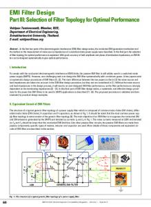
Before discussing various groundmg problems, let us look at the figure 1 which shows various ntra-system coupling paths for a generalized display system
INTRODUCTION
Modem display systems are packed with electronics, which includes fast analog switching circuits, high bandwidth high power amplifiers, micro controllers, low voltage power supplies, high voltages power supplies, display devices etc. The performance of these devices and circuits can be adversely affected by electromagnetic interference. In addition to this, EM1 problems can be compounded due to critical missions (in medical devices instruments and display systems in the area of aviation) and harsh EM1 environments (like working of display devices in vicinity to several other EMI generating and sensitive instruments in case of fighter aircrafts). Designing a display system requres careful understanding of environment where the systems requires to be operated and the influence of the subsystems.
Proceedings of INCEMIC - 2003
- - - - - -. . .
Field to Cable power Supply coupling
Common Mode Ground L q Cauphg Cable to Cable
-. -.
- .- .
"PCB
Power SqplY to PCB Fipure 1 htra system couplingpab
2.1 Common Ground impedance coupling arises due to conductive interference where return path is shared by number of circuits. Since practical reference conductordplanes do not exhibit zero impedance, any
191
current flowing in such paths will produce potential difference between points on the reference ground and the interfacing circuits. Circuits referenced to these points will experience conductively coupled interference. That is, if the ground i m p e k e in this retum path becomes significant, it becomes the main cause of EMI. Common ground impedance converts ground currents to a common voltage, which acts as a potential source of EM1 to push currents around the loops in the concemed circuit$ cables and tracks connected to them. The resulting differential mode voltage component developed in the victim cable appears across the amplifier or logic input terminals to constitute the potential EMI threat. The common impedance ground coupling can be reduced either by reducing the common ground impedance or by reducing ground currents i.e., the product & x has to be reduced. Ground Loops are major cause of failure of grounding in any system. A ground loop is formed when a short to ground occurs in the ground scheme. The reason ground loops are detrimental to display related circuits/equipment is that when they occur, stray currents begin to flow within the ground conductors. The stray currents consequently induce noise in the ground reference and induce into the signal lines of the system. The current will be a function on the size of the loop andor the strength of the magnetic field. If the field increases or the loop area increases the current will increase. Obviously the EMI problem associated with this, then, increases with the loop area or the magnetic field strength. Similarly conductor Impedance also has to he considered while designing grounding scheme. The conductor impedance is proportional'to the frequency. The two main effects that increase impedance are the skin effect and the inductance of the individual conductor. One explanation of skin effect is that the intemal inductance of a wire increases towards the center making current flow easier toward the outside of the wire. The effect of his is that at very high frequencies most of the current flows around the outside of the conductor and consequently the conductor have effectively a smaller area causing its resistance to increase. The incremental selfinductance of a single piece of wire is a function of its length and the radius of the conductor in centimeters. A piece of wire with a bend in it will have a greater inductance than a single straight piece. Therefore, it is important to route ground conductors with a minimum number of bends and turns. Due to of the skin effect it is very common to use braided conductors or flat pieces of copper plate or ribbon.
192
2.2 Common mode induction or radiation is a radiated interference situation due to ground loops. The ground loops formed in the circuits will behave like radiators and also receivers of signal; creating radiated emissions and susceptibility problems. The radiated source induces a common mode (CM) voltage in the loop formed by the circuits and a common ground. If the field is predominrntly electric, this CM voltage appears transversely from line to ground. If the field is predominantly magnetic, the CM voltage will appear in series and its value is VCM= - (dBidt) x area In this case, the quality of the ground (resistance or impedance) does not play an important role because the EM1 voltage (for susceptibility) or the emitted field (for emission) is mainly function of interconnect cable length and height above grounding conductor or plane, intentional or fortuitous ground loops created by OV to chassis conductor, earth ground wire, stray capacitance etc.
2.3 Single Point (Star) Grounding, Multipoint Grounding, Hybrid Grounding - The individual ground planes from each subsystem can be finally connected by the shortest route back to the ystem ground point where they form an overall potential reference. This is called as single point or star grounding. It reduces common mode impedance coupling problems. However, common impedance ground currents may still flow. Other problem can be of parasitic capacitance between subsystems chassis and ground of the same system or the other system's ground providing low impedance paths at higher frequencies leading to common mode currents flowing among subsystems. Figure 2 and 3 shows case of improper and single point grounding scheme for a generalized display system. For higher frequencies, a multipoint grounding
scheme provides common low impedance equipotential ground plane with " k d common mode currents. Hybrid grounding allows satisfactory operatbn at both low and high frequencies. In hybrid grounding scheme, the system-grounding configuration employs both single and multipoint grounds. A low frequency ground current loop would be generated were it not for the capacitor. Example for this is a coil driver circuit where both the sense and the chassis of the driver circuit is grounded to the system's chassis and the coaxial cable shield is grounded at both ends through its mating connector. At bigb frequencies, the capacitor assures that the cable shield is grounded to brotect the faraday shield effect.
Proceedings of INCEMIC
- 2003
Figure 3 Single Point Grounding
3. EM1 PROBLEMS ASSOCIATED WITH DISPLAY SYSTEM AND ITS MINIMISATION THROUGH GROUNDING
A CRT based display system mainly consists of a CRT, analog and digital circuits, passive components, linear power supply, dc to dc converters, high voltage power supply, high current coil driver amplifier, and cahlig & printed circuit hoards for interconnectivity. The quality of the image is influenced by these fimctional blocks. 3.1 Analog and Digital Circuits, Printed Circuit Boards - Digital circuits operate with high speed clock and data transmission rates. A display system may employ a variety of digital components and circuits for various purposes like for sweep generation, gates and flip flops for effecting various control logics, watchdog timer, multiplexers and decodeq crystal oscillators, microcontroller circuits etc. Digital circuits operate at relatively large signal levels and have an inherent immnnity to low-level noise pickups. The high switching speeds, combined with high inductance of the conductor that interconnects them, make them major source of noise.
Digital clocks signal is a composition of a number of harmonic frequencies. As the rise time decreases, the bandwidth of the signal naturally increases which is given by F = [0.35]Rr, where T, is the rise !he in nano seconds For example, a rise time of 1 ns corresponds to handwidth of 350 MHz, and will continue to grow up as the rise times fall fiuther. The fast edge rate (dI1dt
Proceedings of INCEMIC
- 2003
and dE1dt) easily couple energy to adjacent lines or wires. High speed signals with higher bandwidth not only induce into the adjacent conductors hut also are susceptible for noise. Digital raster generation circuit mainly employs counters, DAC and opamps. In counter circuits the output of all the counters changes on the active edge of the clock This phenomenon may result in spikes on the device ground plane called as ground bounce resulting due to simultaneous switching during high to low transitions. When several outputs switch simultaneously, the total current in the device through the power and ground lead inductance will result in a large transient potential difference between the power connectivity intemal to the device and the power planes. Another reason for temporarily rise in the voltage of the ground plane under a very fast changing signal track is due to capacitive effects. This is called as secondary ground bounce. The digital circuits can he severely affected by the ground noise, which may he produced by power supply and signal retum currents. Transient ground currents are a primary source of intra system noise, conducted and radiated emissions. Apart from this, highspeed digital circuits are also vulnerable to electrostatic discharge, which may occur due to things like signal pickup and ground bounce. This can create permanent or temporary damage and/or malfnnctioning of unprotected U 0 ports, reset, control lines etc. In analog circuit, a small amount of extemal noise coupled into the circuits can cause interference, which can occur in circuits at very low signal levels and/or containing high gain amplifiers. External noise sounes are usually primary concem and susceptibility is the main threat. RF interferences are a big problem with analog circuits. The high levels of RF energy can drive unprotected low-level analog circuits into nonlinear operation. An example for this can he a monitor whose performance can become faulty in case of presence of false signal in the analog processing chain. Therefore, it is necessary to isolate W from analog circuits. The analog circuits themselves may not he typical sonrces of EM1 hut their performance can be severely affected by noise from nearby digital circuits, switching power supplies, and often 50160 Hz power line currents and fields. The analog circuits where operating signal levels are smaller, they are more vulnerable to EMI. Ifthe noise and signal level and ADC detectable limits are of
193
same amplitude, the system will he influenced by false higgering.
noise from rectifier switching and the switching regulators.
Printed Circuit Board Design - The design of PCB layout and proper consideration of grounding scheme in PCB layout plays a crucial ole in minimizing EMI. By using multilayer hoards, the power and ground loop areas are reduced thereby reducing boards radiated emissions and susceptibility. In addition to this, nearby power and ground planes reduces crosstalk between traces considerably and also the power and ground impedance levels are reduced. Since the current carrying traces are placed closely parallel to conductive ground and power planes, most of the high frequency current will return directly under the trace flowing in the opposite direction. This forms a transmission line with the mirror image of the trace on a plane. As currents are equal and opposite in it, the electromagnetic emissions and pickup are considerably reduced. Ground and power planes should preferably be on different layers. For low frequency signal high frequency isolation, the power and ground planes are taken through a femte heads. For high frequency digital and analog signals, traces often act as unwanted antennas that both transmit and receive radiations.
The linear power supplies may be used in a display system which may employ a transformer to provide a voltage output of sufficient amplitude to provide adequate voltage followed by a rectifier, ripple filter and fmally to a regulator. This kind of power supply is good from EM1 viewpoint but there efficiency are on lower side and also they are bulky because of more heat dissipation.
ADC Grounding - The ADC has got intemal isolated analog (AGND) and digital ground-references (DGND).When the digital outputs of the ADC switch are low, the DGND pin carries large, highspeed currents. These currents induce transient voltages across the inductance of the DGND pin. This ground bounce noise, also called simultaneous-switching noise, makes the voltage on the intemal chip-ground net (or substrate) different from the voltage on the PCB ground. The groun4hounce noise may not bother the digital bgic, which has a high tolerance to noise, but it makes the digital ground net useless as an analog reference voltage. The AGND pin solves this problem. As long as the intemal analog circuits don't pump much current through the AGND pin, there is not muchof a voltage drop across its inductance. The intemal analog circuits connected to the AGND pin therefore get a true, quiet indication of the actual PCB ground voltage at the AGND via. Hence on PCB, the AGND and DGND pins should be tied together. 3.2 Power Supplies - Power supplies are both a source and conduit for interference. They generate
194
Normally switching mode power supplies are used in modem display electronics. These supplies consist of two basic elements: AC to DC conversion followed by DC-t@DC conversion. In case of former type of conversion, a high speed switching oscillator (20 - 50 KHz or 500 KHz range) are being employed. Though efficiency of switching power supplies are very high and are smaller in 'size, but generate considerable amount of EMI. The switching edges are designed to be as fast as possible, as, the faster the switch, the lower the power drawn in the switching device itself. Another problem lies in the form current 'spikes drawn during switching which often occurs with puskpull designs where both switches may be on for a brief time. The abrupt switching transitions involving energy storage devices also often result in current or voltage spikes far in excess of that needed for operation. The spikes not only contribute to high frequency noise flowing through the supply. This can be caused ly power feed wires intercepting RFI and transmitting it directly to the supply. Severe ground problems can result due to improper wiring. There is a very common fault of interchange of neutral and earth connectors and can lead to stray noise problems. The full load current of terminating equipment returns through the earth wire. The resultant common mode voltage and current pose a severe threat to interconnecting circuits between equipments. In case live and neutral wires are interchanged, there is power frequency common mode noise because of the higher voltage developed by the return current traveling through the longer path. Voltage drop in case of reversal of earth and neutral wire leads to voltage drop associated with return load current and then appear as common mode noise source between separately located equipment. 3.3 Coil Drivers - A CRT, which has electromagnetic deflection system, requires a driver circuit to position the beam on CRT face. The driver circuit is configured as voltage to current converter with
Proceedings of INCEMIC
- 2003
sensing the current through a sense resistor of a very low value. The impedance in input signal ground and common point of sensing resistor will cause the variation in magnitude of actual drive signal for the CRT. The power op amp used is of high slew rate with fast settling time, high bandwidth and high output current. The driver circuit based on the w e of opamp could influence adjacent circuits and get influenced by EMI. In power amplifier circuit, f the phase of the signal is in phasewith the signal at the node it is fed hack to resulting in positive feedback and could lead to oscillation. Although these parasitic resistances in the load current return line can not he eliminated, they can be made to appear as a common mode signal to he amplifier by the use of a star ground approach in which the ground points of amplifier, signal and the power supply are connected to the common point. A short conductor length reduce ground impedance between power and the signal ground. It will also provide a p r o p reference for the sensing resistor therehy amplifier responding truly as current to voltage conversion mode The cases of all the power op amps are isolated to allow mounting flexibility but they can act as antennas in the video frequency range and cause errors or even error as the cases in close proximity to all the internal nodes of the amplifier. Providing a connection from case to ground forms a faraday shield around the power op amp’s internal circuitry that prevents noise pickups and cross coupling or positive feedback.
and thus minimizes magnetic coupling. This phenomenon is called as ducting.
In analyzing shielding it is helpful to consider the three types of fields that occur. If &nes waves exist greater than about 1/6 of a wavelength from the source, the ratio of the electric field to the magnetic field is a constant and equal to 377 in free space or air. The field is known as a far field or a radiation field. Examples of this are radio waves. If it is less than 1/6 of a wavelength to a high impedance source, the wave impedance is greater thin 377. This is known as the nea field and capacitive energy dominates. In the near field the losses are greater because of the higher wave impedance. This is why it is possible to do effective shielding from electric fields. Another way of looking at this is that electric fields produce voltages in victim circuits. If it is close to a low impedance source, in other words a current source, the wave impedance is less than 377. This is also the near field, but in this case inductive energy predominates. Reflection losses are much less here because of the lower wave impedance and this problem worsens with drop in frequency. This is the reason that shielding is ineffective against low frequency magneticfields 4.1 Shield Selection - While designing a shielding mechanism, shielding material is selected based on their permeability based on potential source of interference (whether radiated ort susceptibility) is from electric or magnetic field, frequency at which interference is expected.
4 REDUCTION OF E M IN DISPLAY SYSTEM THROUGH SHIELDING METHODS
The shielding is effected by two mechanisms: reflection and absorption In shielding by reflection, the EMI energy is reflected hy the shield surface and works well for low frequency electric fields and for high frequency electromagnetic fields. In shielding by absorption phenomenon, the EM1 energy penetrates into shield boundary and is absorbed as it traverses the media and comes into effect to shield low frequency magnetic fields. Therefore, providing a sheet cover of high permeable material like Mumetal of sufficient thickness on power op-amp circuithoard provides an effective shielding to nearhy circuits against low frequency magnetic fields. The permeability of materials like Mumetal, iron falls at high frequency hut still provides shielding up to 1 GHz. This kind of magnetic shielding with highly permeable material concentrates the magnetic flux
Proceedings of INCEMIC - 2003
Susceptibiliy Shielding - In a CRT based display system for aviation application, there are electromagnetic threats from dc to higher frequencies. The victim in this case is identified as either the most sensitive analog and/or fast logic family or deflection amplifier. The effective use of the system’s outer wall reduces the threat of electromagnetic ambient considerably. Emission Shielding - The radiation due to pulsed sonrces appears as narrow band, but their broadband component should also be considered. Even a small portion of highspeed switch logic power can create radiation which can cause nuisance not only to nearhy circuits of the system itself, but also to other system in vicinity. Radiation from a PCB and associated wiring is expressed by an expression for far field electric term from a short doublet
195
EV/m=(I x [I] x [60]n)/ rh Where I=current in short wire in amperes I=length of short wire in meters distance in meters h=Wavelength in meters The finite spacing between traces or wire canying opposite currents can result in net radiating field. The radiated loops can consist of the +5V DC and return traces to the chip, in which case, radiation is caused by the dynamic current drawn from the power bus during logic transitions; the chip and logic and socket leads; the signal and retum traces between chips, the r e m being the corresponding OV traces; the signal and retum wire in a flat cable.
Figure: 4 (a) Physical relelationshi~@) Equivalent circuit @)Amplifier shield mmected to amplifier common
Enclosure Shielding The metallic enclosure of any good conductor material like aluminum will effect reflective shielding against low frequency electric fields and high frequency electromagnetic fields. But shielding fails wherever there are breakages in the shield like a thin slit in the seam, slots for cables, improper mating between two surfaces leaving a gap. The electrical gasket around the periphery of mating top and base cover and similar types of mating results in significant emission reduction from leakages and susceptibility suppression. EM1 gasket with properties of combination of an electrical and a pressure seal helps to fill the gaps, which may be due to irregularities into mating surfaces. EM1 gasket made of suitable conductive material helps conductively closing the between two mating surfaces. Conductive elastomer has metal filaments thereby providing conductivity between two mating surfaces.
4.2 Shield Grounding - The ideal EM1 shield forms a continuous conductive layer wound those circuitsicomponents that it protects. In case of twisted shielded pair cable, there is an opening in the shield at the connector. By connecting the shield to the ground of the equipment case the continuity of this shield is improved, however, clearly it is far from perfect as the conductors are clearly exposed. In the case of coaxial connectors such as BNC's, the shield makes a circumferential connection to the cable connector and that in turn makes a circumferential connection to the panel-mounted connector providing 100% coverage of the inner conductor. In the case of coaxial cable, we have 100% shielding throughout the length of interconnect and we have a ground loop that is formed between the send and received ends. This has always been one of the difficulties of the single ended routing of final video signal to the CRT cathode or grid as the case may be, in which case one end can be connected to coaxial contact hut some portion of other side cable remains unshielded as it has to be terminated directly.
In addition to this, various sensitive subsystems are required to be shielded for preventing the misbehavior in form of oscillation. Hence, high gain amplifier is required to be closed in metallic shield to provide protection from electric fields. From equivalent circuit, it is seen that stray capacitance C3S and CIS provides a feedback path from the output to the input. If the feedback path is not eliminated, the amplifier may oscillate. The only shield connection which eliminates the unwanted feedback path is one shown in figure 4(c) where shield is connected to the amplifier case. By doing so, C2S is short and feedback path is eliminated.
Figure 5 chassis Grounding scheme for a display system
-
The grounding of chassis of various subsystems and system as a whole helps in minimizing radiated emissions and radiation susceptibility of the system. Figure 5 shows a chassis ground scheme for a system taking input signals from a remote system.
196
Proceedings of INCEMIC
- 2003
Magnetic field attenuation is achieved by means of screen made of a magnetic material combining high permeability with sufficient thickness to attract the material's magnetic field by providing a low reluctance path. Alternatively, a thin shield made of a conductive material with low permeability provide effective shielding for magnetic field because an altemating magnetic field will induce eddy currents in the screen. These eddy currents will themselves create an altemating magnetic field of opposite orientation inside the shell. The effect will increase a frequency increases resulting in high shielding effectiveness at high frequencies. This is especially required o minimize the jitter effect in display because of extemal magnetic fields. For low frequency magnetic field, the shielding mechanism is absorption phenomenon, the EM1 energy penetrates into shield boundary and is absorbed as it traverses the media and comes into effect to shield low frequency magnetic fields. Figure 6 shows the shielding model for low frequency magnetic field shielding. At lower frequency, reflection losses are much less and this is the reason that shielding is ineffective against low frequency magnetic$eld..
hdmlive Coupling to Signal
&valent
Circuit
necessary corrective measures at the time of CR'I design and fabrication. 4.4 Shield Termination - The following rules may be
helpful with regard to the use of cable Shields. Terminate the grounded end of a shielded cable with an insulating sleeve over the jacket termination and a piece of tubing over the ground wire so as to prevent the possibility of the shield becoming inadvertently shorted to another circuit or shield or ground. As an altemative to breaking very long shields into pieces it is possible to use a capacitor as one end of a shielded cable to ground a shield. In other words, one end of the cable is grounded normally with a direct connection to ground and the other end of the shield is grounded via a capacitor to high frequency grounding without introducing a DC ground loop. When terminating shielded cables always keep the nnshielded portion as short as possible. Unnecessary breaks in shielded cables should be avoided, such as at junction boxes, and always maintain shield continuity and isolation from ground, through all boxes or multi pin connectors. Shielded cables that have continuous conductive path around the circumference should be used. Multi connector, shielded, twisted pair cable should have an insulated shield and retum wire for each twisted pair of wires. 5. Routing of cable & reducing crosstalk between cables
Shield p r ~ v l d e~urrpnt ~ path
Equivalent Circuit
Figure6 Shielding Madel for Low Frequency Ma@&
V
Field Shielding
4.3 Leakagefiom CRT - The leakage from CRT is a major source of concem. Field intensities of 10-100 milliGauss can cause the CRT displays to oscillate. These fields can be from intemal electronics but is mostly due to extemal power wiring. The display openings can be shielded by incorporating laminated screen windows, transparent, conductive substrate or backside mounted shields. Since CRT is also vulnerable to VLF H fields such as power mains magnetic fields, nearby powerful converters etc, it is essential to choose a CRT with effective shielding. The example of such kind of interference is monitor color getting changed when placed near high power motor. The CRT manufacturer can incorporate all the
Proceedings of INCEMIC - 2003
Cables acts as unintended antenna at high frequencies for radiated EMI as any cableltracelwire over U20 long acts as antenna for EM1 radiation. For example, for frequency 300 M H z , cable length of h=clf=0.5m will radiate. As frequency of operation increases, the length of the cable sufficient to act as antenna rapidly decreases. The physical separation of cables has a significant effect on their interaction with each other. The effects of the separation of parallel wires are govemed by the 3 dB per doubling d distance rule and this applies to both electric and magnetic fields. The wire inductance at frequency of order of 300MHz is Z=236t=15Q. The impedance of this order will cause power and grounding problems. Apart from using power and ground planes, specil care has to be taken in terms of shielding cables which carry these high speed signals as they are likely to upset the performance of nearby circuits. The cable current flows in common mode, which means there is
197
no nearby return current to help cancel h e radiation. In this case even a small fraction of the initial energy can create EMI if cable length is more and not shielded. The CM radiation is many times stronger than the board radiation hence apart from blocking EMI at the point of entering and leaving the boards through filtering. The cables are susceptible to reflection and crosstalk prohlems(figure 7). The crosstalk is due to near field electric field and magnetic field coupling between adjacent lines in the cable. The capacitive coupling is predominant in digital and high impedance analog interfaces (video amplifier and driver), while the inductive coupling is the culprit usually in power interfaces and low impedance analog interfaces (high current coil driver amplifier). The capacitive and the inductive coupling can he reduced by increasing wire separation and/or parallel m, decreasing separation between signals and associated return lines, slowing down of edge rates and frequency. For capacitive coupling, adding a shield or guard trace helps, while for inductive coupling shielded twisted wire pairs helps which provide some cancellation of the inductive path.
w
LL-n-va Figure 7 Cablr:Crosstalk Modelwith capacitive & Inductive Coupling modPS
loop area formed by the ground path and the farthest conductor is huge, making good antennas for emissions or immunity Adjacent signals are fully exposed to adjacent line coupling or crosstalk. To get rid of this problem, the grounds should he spread throughout the cable, preferably not more than five signal lines per return line. This minimizes loop areas, minimize adjacent line crosstalk, " i z e ground bounce and thus " i z e both emissions and reception of external interference. 6. CONCLUSION
The components and modules required for a display system requires proper implementation of grounding and shielding scheme. The influence of EM1 on performance of systems can largely be improved by incorporating hybrid devices, using flexi shielded PCBs, shielded connectors, multilayer boards, cables with built in shielding provision and optimizing signals speeds. 7. REFERENCES
[I] Michel Mardiguian, 1988, Grounding and Bonding Handbook, Volume 2, Interference Control Technologies, Inc. Gainesville, Virginia. [Z]Michel Mardiguian, 1988, EM1 Control Methodology and Procedures Handbook, Volume 8, Interference Control Technologies, Inc. Gainesville, Virginia. [3] Dr.Sisir K Das, 2002, "EMC by Electromagnetic Shielding", 7* International Conference on Electromagnetic Interference and Compatibility, 2002, Bangalore. [4] m i t e D.R.J., 1981, Emi Control in the Design of PCBs and
Interference always starts as differential mode, but coupling paths are always common mode. Differential mode is generated between two terminals of a device and generally propagates as noiseheturn paths. The coupling paths from a noise source are largely common mode. Either inductive or capacitive coupling from a wire of a circuit member to an adjacent bundle is largely common to all the wires in the bundle. As the distance form the source increase, the common mode interference on wires increases. The common mode currents must return through some path other than the cable, which may be another cable, the ground or some leakage path. In Differential mode, current flows in both directions, so the current is in the cable itself. The CM EM1 is coupled to the cable through radiation, crosstalk or common ground impehce. The ribbon cables are used for carrying mostly carrying digital signals. Since there are too many conductors for the number of ground conductors, the ground noise may result which will affect the performance of the chip to which it is going. Further,
198
Backplanes, Gainesville, Virginia: Interference Control Technologies, Inc. [5] William G. Duff,1988, Fundamentals of Electromagnetic Compatibility Handbook, Volume I, Interference Control Technologies, Inc.Gainesville, Virginia. [q [I] Morrison, R. 1977. Grounding and Shielding Techniques in Insmentation, 2nd ed., New York Wiley Interscience. [7l Violene, N., and White, D. 1987. Electromagnetic Compatibility Handbook, New York Van Nostrand Reinhold. [8] KaufmaM, R. H., 1954. "Some Fundamentals of Equipment Grounding Circuit Design", AIEE Transactions, November, pp. 227-232. [9] On, Henry W. 1988. "Noise Reduction Techniques in
Electronic Systems", Second Edition, John Wiley and Sons. [lo] Morrison, Ralph, 1986. "Grounding and Shielding Techniques in Instrumentation", Third Edition, John Wiley and
sons. [l 1] "ADC Grounding" EDN, December 2000)
Proceedings of INCEMIC
- 2003