significant factor, as was the camera mode factor. See the Results and ... that (i) perspective projections offer a realistic view of a 3D environment akin to our. 5 ...
Technical Report no. 2005-11
Reducing Occlusion in 3D Environments Through Smooth Camera Projection Animation
Niklas Elmqvist
Philippas Tsigas
Department of Computer Science & Engineering Chalmers University of Technology and G¨oteborg University 412 96 G¨oteborg, Sweden
G¨oteborg, 2005
Abstract Inter-object occlusion is intrinsic to 3D environments and is one of the main problems of using 3D instead of 2D computer graphics for information visualization. In this paper, we examine occlusion in depth, both in a theoretical treatment as well as in an empirical user study. Furthermore, we present an interaction technique for camera projection animation that reduces inter-object occlusion in 3D environments without modifying the geometrical properties of the objects themselves. The technique provides smooth on-demand animation between parallel and perspective projection modes as well as online manipulation of view parameters, allowing the user to quickly and easily adapt the view to avoid inter-object occlusion. This also simplifies object access by supporting 3D picking in ortographic mode. Our user study indicate that the technique significantly improves object discovery over normal perspective views. By treating the 3D objects in the environment as immutable entities, the technique is non-invasive and can seamlessly be integrated into any kind of 3D visualization. Keywords: occlusion, 3D visualization, parallel projection, perspective projection
1
Introduction
While the use of three-dimensional computers graphics in visualization provides useful and sometimes even necessary potential for various visualization applications, there is an increased overhead associated with using 3D over conventional 2D graphics for the purpose of orientation and navigation within the environment. In general, 3D graphics impose a high cognitive load on users trying to gain and maintain an overview of the environment, as well as traversing it, and often cause disorientation, confusion, and sometimes even nausea. One of the central issues behind this effect is occlusion, the phenomenon that nearby objects occlude more distant objects in 3D even if the objects are not overlapping in space (see Figure 1). This issue is unique to 3D environments and is also present in the real world; in a computer visualization, however, we can do something about it.
Figure 1: Complex scene with a high degree of inter-object occlusion. Why is occlusion a problem in 3D visualization environments? There are two basic issues. First of all, and perhaps most seriously, there is a discovery problem if an object is occluded since then the user may never know that it is there. And secondly, even if the user is aware of an occluded object, there is an accessibility problem, since the user will have to move the viewpoint in some nontrivial way in order to retrieve the information encoded in the occluded object. In this paper, we focus on the first of these two issues, examining the impact of inter-object occlusion on object discovery efficiency through a formal user study. Our results indicate, not surprisingly, that occlusion becomes a significant detriment to object discovery as the object density in a 3D environment increases. Naturally, it is in our best interest to try to reduce or eliminate this problem, but few such methods exist. Accordingly, the second contribution of this paper is a novel interaction technique for camera projection animation that aims to reduce inter1
object occlusion in 3D environments without modifying the geometrical properties of the environment itself, nor the objects in it. The technique allows for smooth animation between the conventional perspective projection mode, which mimics human vision in the real world and is commonly used for 3D visualizations, and parallel projection mode, where the depth coordinate is ignored and objects are assigned screen space according to their actual geometrical size, regardless of their distance to the viewpoint. Naturally, accurate 3D picking of objects in the scene is supported in all projection modes. In addition, the technique provides ways of manipulating intrinsic camera properties such as the focal length and the center of projection, giving users direct control of the projection mode and allowing them to easily adapt the view to avoid occlusion. Since the technique is non-invasive and does not modify the 3D environment, it can potentially be integrated seamlessly into any kind of 3D visualization. A formal user study conducted on our technique in relation to traditional perspective projection shows a significant improvement of object discovery in 3D environments in our favor. Our results also indicate that, just like in the real world, the ability to move the viewpoint helps users to discover more objects, but our technique still holds a significant efficiency advantage. The cost for this increased efficiency is instead significantly longer task completion times; users essentially trade speed for accuracy when using our technique. On the other hand, the results also show that there is no statistically significant difference in completion times between using our projection animation technique and a user-controlled camera. In fact, we believe that our projection animation technique require less viewpoint position manipulations than normal perspective views, and thus users run a lower risk of getting disoriented when navigating the 3D space. This paper begins with a review of existing work in the area. We then launch ourselves into a theoretical treatment of the occlusion problem and its humancomputer interaction aspects, as well as the mathematical foundation necessary for describing the projection manipulations involved in the interaction technique. After this, we describe the projection animation technique itself. This is followed by an overview of the formal user study we conducted, both for exploring the occlusion problem as well as comparatively evaluating our new technique to normal perspective views, and the results we collected from it. We close the paper with a discussion and some conclusions and future work.
2
Related Work
Improving the usability of 3D visualizations has been a hot topic for a long time, but most effort has been directed towards navigation in 3D environments. While not quite orthogonal to the occlusion problem, this research deals mostly with unified approaches to solving the complex symptoms of a number of different problems inherent to viewing 3D space, occlusion being one. Examples of such work is numerous and include [5, 10, 11, 12, 19] to name just a few. However, there also exists a number of papers dealing more directly with object discovery and access in complex 3D environments. The Worlds-in-Miniature technique [18] uses a miniature 3D map of the environment to support both discovery and access, worldlets [6] provide both global overview maps as well as local views optimized for detail, and bird’s eye views [8] combine overview and detail views of the world. None of these make direct use of the view projection to improve perception; however, temporally controlled non-linear projections [16] have been used to great effect in improving navigation and perception of 3D scenes. Our work differs in that we focus our efforts on investigating and solving the specific problem of inter-object occlusion instead of addressing the more general 3D perception con-
2
cern; our projection animation technique could certainly be used as a component in any of these larger-scale approaches. Projections are intrinsic to computer graphics, but are mostly limited to linear perspective projections. CAD programs have traditionally made use of parallel projection, often through the use of multiview orthographic projections where two or more views of the same object are shown on planes parallel to the principal axes. Carlbom and Paciorek [4] (see also [13]) give a complete overview of planar geometric projections and their various advantages and disadvantages in different situations. Recent developments in the area also include multiprojection rendering, where several perspectives are combined into one, mainly for artistic purposes. Agrawala et. al [1] compose views of multiple cameras, where each object is assigned to a specific camera perspective, allowing for creative scene composition akin to the work of famous painters. Singh [15] uses a similar approach, but smoothly combines the multiple viewpoints into an interpolated virtual camera instead of combining the images of disjoint cameras on an image-level. While only weakly related to our technique, these works give interesting insight into the manipulation of projection transforms and could conceivably be used for assembling the views of several strategically placed cameras into one image in order to further reduce inter-object occlusion. Finally, our projection animation technique also allows for interactive manipulation of camera properties beyond the traditional position and orientation parameters. Prior work in this area include the IBar [17] camera widget, which is a comprehensive camera control that provides intuitive ways of manipulating these parameters for the purposes of 3D scene composition. Another approach uses imagespace constraints to solve for the camera parameters given a number of control points [3, 9]. Our work is again focused on reducing objects obscuring other objects rather than direct camera control, and the camera manipulations provided by our technique only give additional means to achieve this.
3
Background
In this section, we first explore the occlusion problem in 3D environments from both a theoretical as well as a practical viewpoint. We present results from a formal user study to support our claims. Second, we give a brief mathematical background of planar geometric projections for the purposes of designing our interaction technique.
3.1 3.1.1
The Occlusion Problem Model
We represent the 3D world U by a Cartesian space (x, y, z) ∈ R3 . Objects in the set O are volumes within U (i.e. subsets of U ). The user’s viewpoint v = (M, P ) is represented by a view matrix M that includes the position and orientation of the user, as well as a projection matrix P that includes viewport dimensions, focal length, far and near clipping plane, etc. In our treatment, the geometrical position and shape of objects o ∈ O are immutable (i.e. they may not be changed by external sources since we are looking for non-invasive methods), but object properties (such as color, texture, opacity, etc) as well as the geometrical properties of the viewpoints may be modified. An object o may be built up from a lot of different surfaces, but a ray r is said to intersect the object o if the ray intersects any part of o. A ray can only intersect o once, even if there is more than one geometrical intersection. Each object o has an associated opacity value that is common to the entire object. 3
A ray r is blocked by an object o if r intersects o and the accumulated opacity value, as the ray is traced from a viewpoint v to the current object o, becomes greater or equal to 1 (i.e. 100 % opacity). If the ray is not blocked it is said to pass through object o. Passing through an object will increase the accumulated opacity value of the ray. A blocked ray does not penetrate through the object blocking it. An object o is said to be occluded (or fully occluded) from a viewpoint v if there exists no ray r between v and o such that r is blocked by no object. Analogously, an object o is said to be visible from a viewpoint v if there exists a ray r between v and o such that r is blocked by no object. An object o is said to be partially occluded from viewpoint v if o is visible, but there exists a ray r between v and o such that r is blocked by another object. A set of viewpoints V is said to be complete if there exists no object that is occluded in all of the viewpoints vi . 3.1.2
Analysis
Given the above definitions, we can categorize the general occlusion problem as consisting of two main parts: i) object discovery – finding all objects o ∈ U in the environment, and ii) object access – retrieving graphically encoded information associated with each object. Object discovery efficiency is severely hampered by the existence of fully occluded objects, whereas object access also suffers for partially occluded objects. Both issues will affect the efficiency and correctness of users solving tasks using a visualization, but clearly, object discovery is the most serious of the two; if the user is unaware of the existence of an object, she will have no motivation to look for it and access never becomes an issue. This paper deals primarily with object discovery, although we plan to address object access in the future. The most common way to overcome partial or total occlusion is to change the position and orientation of the viewpoint (i.e. primarily the view matrix M for the viewpoint). This is akin to the real world, where occluded objects are discovered and accessed by walking around in the 3D environment. In this paper, we take a different approach and instead modify the projection matrix P to help reduce the effects of occlusion. It is worth noting that partial occlusion can affect object discovery efficiency as well, since users may have difficulties distinguishing object identity if too large a portion of the object is occluded. In this situation, the user may either miss the object entirely, count the same object multiple times, or believe different objects are part of the same object. Thus, occlusion is not a pure geometrical problem, but also involves aspects relating to human cognition. 3.1.3
User Study
One of the two motivations driving the formal user study conducted as part of this work was to empirically investigate the actual impact of occlusion on object discovery efficiency in 3D environments. We use the control group condition (no camera projection animation, i.e. “PMorph” is off) in the user study for this purpose. Furthermore, we are also interested in determining the benefit of having a movable camera over a fixed one; our intuition is that being able to move around the 3D environment will significantly increase object discovery efficiency. Both intuitions turned out to be correct; the object density was a statistically significant factor, as was the camera mode factor. See the Results and Discussion sections for details on the outcome of the user study. 4
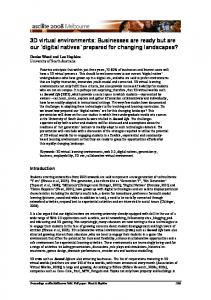
z far
view frustum
view plane
near 0/2 0/2
center of projection x
left
right
Figure 2: Perspective projection view frustrum seen along the xz plane.
3.2
Projections in 3D Computer Graphics
In general, the purpose of a projection is to transform points in an n-dimensional coordinate system into points in an m-dimensional coordinate system where n > m. In the case of computer graphics, this is specifically done by transforming 3D points to the planar 2D viewport (since most display devices are limited to two dimensions). In addition, the 3D projection transform also removes points that fall outside of the 2D viewport; this process is called clipping. In this discussion, we limit ourselves to planar geometric projections, i.e. projection onto a plane, since these are the projections commonly used in computer graphics. A 3D projection transform is defined by a center of projection and a projection plane; projection rays, called projectors, originate at the center of projection to pass through each point in the 3D object, intersecting with the projection plane to form the 2D projection. The projection transform can be characterized by these two parameters: if the distance between the center of projection and the projection plane (sometimes called the focal length) is finite, the projection is perspective; if the distance is infinite, it is parallel (the projector rays are parallel, hence the name). According to Foley et. al [7], the visual effect of a perspective projection, where the size of a projected object depends on its distance from the viewpoint, mimics human vision and is known as perspective foreshortening. Although realistic, and thus widely used in 3D computer graphics applications, this projection does not lend itself well to measurement and shape comparison between different objects: distances cannot be measured reliably and parallel lines do not project as parallel. Parallel projections, on the other hand, do preserve relative size and parallel lines, but offers a less realistic view of the 3D scene, and is thus often limited to use in CAD applications. See the appendix for more details.
4
Camera Projection Animation
The idea behind our technique for camera projection animation is to combine the major virtues of parallel and perspective projections outlined in the previous section: that (i) perspective projections offer a realistic view of a 3D environment akin to our
5
B
B
A
A
Figure 3: Comparison of perspective and parallel projection modes in terms of occlusion. perception of the real world, and that (ii) parallel projections offer an accurate and exact view of the environment. Furthermore, the nature of parallel projection means that inter-object occlusion is reduced in comparison to perspective projection since objects are assigned screen space according to their geometrical size only, regardless of their distance to the camera. Using perspective projection, a tiny object can fill the whole viewport if the viewpoint is located sufficiently close to it. See Figure 3 for an example of this scenario, where the same environment is shown using a perspective and parallel view transform, respectively. Note that in the perspective case, the object B is occluded by A, while it is perfectly visible in the parallel case. By combining these two projection modes into the same interaction technique, we are potentially able to enjoy the best of both worlds: the view defaults to perspective projection when the user is navigating the space normally, but allows for easy switching to parallel projection when the user needs to perform object discovery or access. Furthermore, the transition between perspective and parallel projections, and vice versa, is smoothly animated to allow the user to maintain context of the environment and the projection at all times with a minimum of cognitive overhead. The transition is performed on the order of a second, striking a good balance between speed and convenience [14]. In addition to transitions back and forth between perspective and parallel projections, we augment our technique with functionality to change the center of projection as well as modify the field-of-view angle in the perspective projection mode. Changing the center of projection gives an additional means for the user to arbitrate between occluding objects, and by gaining control of the field of view, the user can smoothly zoom in and out of the 3D environment at will. Figure 4 shows a state diagram of our interaction technique. We define three input buttons, labelled “proj”, “util”, and “shear”, respectively; these can be mouse or keyboard buttons. In addition, the technique also captures mouse motion for some parameter changes, notably the field-of-view and center-of-projection modification states. The parallel projection mode has a number of pre-defined oblique projection modes that the user can cycle between: orthographic (head-on parallel projection) versus cavalier and cabinet projections, where the direction of projection is set at fixed values. Note that for all parallel projection modes, the release of the “proj” input button will smoothly revert the projection back to the default perspective mode. Reverting to the default state will also reset all view parameters, such as centering the center (or direction) of projection and setting the focal length to the default value.
6
mouse motion (y)
Cavalier Projection
FOV Change
"util":release
"util":press
"util":release
"proj":press
Perspective Projection
start "shear":press
"shear":release
"shear":press
DOP Change
COP Change
mouse motion (x + y)
Orthographic Projection
"proj":release
"util":release
"shear":release "util":release
Cabinet Projection
mouse motion (x + y)
Figure 4: State diagram for the projection animation interaction technique.
4.1
Projection Transitions
Transitions between various projection states are performed through simple linear interpolation between the source and destination projection transforms. In the case of the parallel-to-perspective transition (and its inverse), however, a linear interpolation will yield unsatisfactory results due to the non-linear relation between these two projections. For this case, we need to explore the matrix M that relates the two projection matrices Ppar and Pper (see the appendix for details). As discussed above, a parallel view transform represents the situation where the focal length of the camera is infinite. The transition from perspective to parallel view can be approximated in a real-life camera by a so-called “zoom and dolly” operation, where the camera is moved backwards at the same time as the focal length is increased (i.e. zoomed in). By keeping these parameters balanced, the focused object in the camera view will maintain the same size and shape, but the rest of the scene will appear to be “flattened”. This is the effect we simulate in our transition between perspective and parallel projection.
4.2
Implementation
We have implemented our interaction technique in a sample C++ application called PMorph. This application builds a simple 3D environment consisting of a 100 × 100 × 100 unit-sized cube and populates it with n 3D primitives with randomized geometrical and graphical properties. The 3D rendering is performed using OpenGL. The application provides mouse-driven view controls with a camera that can be orbited and zoomed in and out around a focus point in the center of the environment. The implementation of the interaction technique itself hooks seamlessly into the input handlers of the windowing system and requires no additional modification to the implementation of the 3D environment, nor the 3D objects. Figure 6 shows two example screenshots from the application, indicating the visual difference between perspective and parallel projection modes. In addition to the implementation of the technique itself, we also implemented a
7
Figure 5: The projection mode overview window.
Figure 6: Screenshots from the PMorph application showing the same view in perspective and parallel projection. projection mode overview window that gives a visual indication of the current state of the interaction technique as well as the view parameters (see Figure 5). Using this window, users can quickly and easily see how their changes to the projection mode translate to modifications to the view volume and the direction of projection.
4.3
Case Study: Blender Implementation
In order to study the feasibility and flexibility of our projection animation technique, we also implemented it inside the Blender [2] 3D modelling package. Blender is a very powerful and widely used 3D software suite that is freely available as Open Source under the GPL license. Our implementation integrates seamlessly into Blender and allows for modellers to animate between parallel and perspective projections in different 3D windows; the software naturally already supported these projection modes prior to our modifications, so we changed the projection code to perform a smooth animation between the two matrices. In addition to this, we introduced the capability for users to change the center of projection while in orthographic mode, allowing for an additional way to reduce occlusion. Figure 7 shows a screenshot of the modified Blender software; our technique is hard to display in a static screenshot, however, and is better seen in the video accompanying this paper. While a 3D modeller is not the primary target platform 8
Figure 7: Screenshot of the Blender implementation of the projection animation technique. for our projection animation technique, this case study shows that the technique can indeed be implemented seamlessly inside existing 3D applications.
5
User Study
As part of this work, we conducted a formal user study with two main motivations: (i) to empirically investigate the impact of occlusion on object discovery efficiency in 3D environments, and (ii) to study the performance of users given access to our camera projection animation technique in comparison to users with a normal perspective view. For both of these issues, we were interested in exploring the impact of object density versus camera movement. Our hypotheses (guided mainly by intuition and a pilot study involving a colleague at our department) were the following: i) Inter-object occlusion will have an increasing impact on object discovery as object density increases; ii) Our projection interaction technique will significantly improve object discovery efficiency over normal perspective views, at least for environments with high object density; and iii) A user-controlled camera will reduce, or possibly even negate, the negative impact of occlusion on object discovery efficiency. We were also interested in collecting the subjective assessment of the participants regarding the various camera and projection modes. 9
5.1
Subjects
We recruited 26 subjects, six of which were female, from the undergraduate engineering programs at our university. All subjects were screened to have basic computer knowledge, but no previous experience of 3D applications was required. Ages ranged from 20 to 40 years of age, and all subjects had normal or correctedto-normal vision.
5.2
Equipment
The experiment was conducted on a Pentium III 1 GHz desktop PC with 512 MB of memory and running the Linux operating system. All tasks were carried out using the PMorph prototype application. The display was a 19” monitor set to 1280x1024, with the main visualization window fixed at 640x480 size.
5.3
Task
Subjects were asked to perform object discovery in a simple 100 × 100 × 100 environment filled with 3D boxes by counting the number of boxes of a given color (see Figure 1 for an example). Target colors were restricted to one of the primary RGB colors (i.e. red, green, or blue), and all distracting objects were configured to contain no elements of that color component to avoid confusion. Beyond that, each task instance was fully randomized, including the position, orientation, and size of the distractors as well as the starting camera position. At least 1 and at most 10% of the total number of objects were targets.
5.4
Procedure
The experiment was designed as a repeated-measures factorial ANOVA, with the independent variables “density” (two levels, low or high), “camera” (static or dynamic, i.e. a fixed or a user-controlled camera), and “PMorph” (on or off, i.e. whether the projection animation technique was available or not), all of them within-subjects. The dependent variables were the total number of target objects, the number of found targets, and the completion time for each task. See Table 1 for an overview of the experimental design. Subjects received the “PMorph” and “camera” conditions in randomized order to avoid systematic effects of practice; for the “density” condition, the ordering was low to high. Density
Camera
PMorph
low low low low high high high high
static static dynamic dynamic static static dynamic dynamic
off on off on off on off on
Objects
Targets
50 50 50 50 200 200 200 200
1-5 1-5 1-5 1-5 1-20 1-20 1-20 1-20
Table 1: Experimental design. All three factors were within-subjects. The order of the “PMorph” and “camera” conditions were randomized to counterbalance learning effects.
10
Users performed the test in sets of 10 tasks for each condition. Each task scenario was completely randomized, with either 50 or 200 total objects in the environment depending on the density, and up to 10% of them being targets. The camera focus point was fixed at the center of the environment, and the orientation was randomized within 60◦ degrees from the horizontal. Furthermore, the camera was offset sufficiently from the focus point so that all objects in the scene were visible. For each specific condition, subjects were instructed in which features (dynamic or static camera, projection animation on or off) were available to them. Tasks were given automatically by a testing framework implemented in the software and answers were input by the user directly back into the framework, thus requiring no intervention by the test administrator. The software silently recorded the completion time, total target number, and found target number for each task. Each session lasted approximately thirty to forty minutes. Subjects were given a training phase of up to five minutes to familiarize themselves with the controls of the PMorph application. Questions regarding technical issues on the application or the tasks were allowed at any point, but no assistance was given in helping the users solve the tasks. With 26 participants and 10 search tasks for each condition, there were 2080 tasks recorded in total. After having completed the full test, subjects were asked to respond to a post-test questionnaire for their subjective opinion of their experience (see Table 2).
6
Results
We divide the results from the user study into correctness, completion times, and subjective ranking categories. Note that for the correctness measure, we derive the cumulative errors for each task set from the sum of the differences between the total number of targets and the found targets for each task. The error ratio is defined as the cumulative error divided by the sum of the total number of targets for the task set, i.e. the number of errors per target.
6.1
Correctness
The average error ratio for a full task set (10 tasks) using normal perspective projection compared to projection animation was 0.095 (s.d. 0.003) versus 0.055 (s.d. 0.003), respectively. This is a statistically significant difference (F (1, 25) = 75.757, p < 0.001). Not surprisingly, density had a significant impact on correctness (F (1, 25) = 407.290, p < 0.001); the average error ratio for the low density condition was 0.022 (s.d. 0.002), to contrast with 0.127 (s.d. 0.005) for the high density condition. This suggests that occlusion does negatively affect object discovery efficiency. For the low density, the mean error ratio was 0.033 (s.d. 0.004) for normal projection and 0.012 (s.d. 0.003) for projection animation, versus 0.157 (s.d. 0.006) and 0.097 (s.d. 0.006) for the high density case. Both of these pair-wise differences are significant (F (1, 25) = 13.493, p = 0.001 and F (1, 25) = 55.176, p < 0.001, respectively), see Figure 8 for a diagram. Furthermore, in the low density case using a static camera, the ratio was 0.60 (s.d. 0.008) versus 0.019 (s.d. 0.005) for normal projection versus projection animation, respectively; this was also a significant difference (F (1, 25) = 14.595, p = 0.001). Analogously, for the low density case using a dynamic camera, the ratio was 0.006 (s.d. 0.003) versus 0.004 (s.d. 0.002); this, however, was not a significant difference (F (1, 25) = 0.240, p = 0.629). On the other hand, in the high density case using a static camera, the average error ratio
11
0.18
error
0.16 0.14
error ratio
0.12 0.1 0.08 0.06 0.04 0.02 0
Low/Off
Low/On
Hi/Off
Hi/On
Figure 8: Mean error ratios for solving a full task set (standard deviations are shown as error bars). was 0.234 (s.d. 0.009) for normal perspective and 0.115 (s.d. 0.007) for projection animation. This is again a significant difference (F (1, 25) = 183.217, p < 0.001). In comparison, for the high density case using a dynamic camera, the ratio was 0.081 (s.d. 0.008) versus 0.080 (s.d. 0.008), also not a significant difference (F (1, 25) = 0.006, p = 0.941). Finally, the camera factor had considerable bearing on correctness; error ratios for static camera averaged at 0.107 (s.d. 0.004), whereas dynamic camera error ratios averaged at 0.043 (s.d. 0.003), a significant difference (F (1, 25) = 199.284, p < 0.001).
6.2
Completion Times
The mean completion time of solving a full object discovery task set (10 tasks) using normal perspective projection was 128.093 (s.d. 7.803) seconds, whereas the mean completion time for projection animation was 162.311 (s.d. 9.697) seconds. This is also a significant difference (F (1, 25) = 38.752, p < 0.001). Again, the main effect for density was significant (F (1, 25) = 108.887, p < 0.001), with mean completion times for low and high conditions of 81.384 (s.d. 4.025) and 209.20 (s.d. 14.086) seconds, respectively. For the low density condition, the mean completion time was 75.796 (s.d. 4.012) and 86.972 (s.d. 4.420) seconds for the normal projection and the projection animation technique. For the high density, the completion times were instead 180.414 (s.d. 12.680) and 236.995 (s.d. 16.053) seconds, respectively. Both of these differences are significant (F (1, 25) = 19.363, p < 0.001 versus F (1, 25) = 30.797, p < 0.001), see Figure 9 for a diagram. Furthermore, for the low density case using a static camera, the mean completion time was 69.737 (s.d. 4.298) versus 89.152 (s.d. 4.339) for normal projection versus projection animation; also a significant difference (F (1, 25) = 36.638, p < 0.001). Similarly, for the low density case using a dynamic camera, the completion time was 83.817 (s.d. 4.933) versus 85.387 (s.d. 5.256) seconds; this is not a significant difference, however (F (1, 25) = 0.226, p = 0.639). In the case of the high density condition with a static camera, the mean completion time was 114.049 (s.d. 5.114) for normal perspective projection as opposed to 200.245 (s.d. 14.683) for projection animation, a clearly significant difference (F (1, 25) = 53.824, p < 0.001). Finally, for the high density case using a dynamic camera, the completion times were 246.778 (s.d. 22.461) versus 273.745 (s.d. 20.998), a nonsignificant difference (F (1, 25) = 2.504, p = 0.126). Analogously to other factors, the main effect on completion time for the camera 12
260
time
240 220 completion time
200 180 160 140 120 100 80 60
Low/Off
Low/On
Hi/Off
Hi/On
Figure 9: Mean completion times for solving a full task set (standard deviations are shown as error bars). mode was significant (F (1, 25) = 46.874, p < 0.001); static camera completion time averaged at 117.267 (s.d. 6.266) seconds, whereas the dynamic camera completion time average was 173.137 (s.d. 11.569).
6.3
Subjective Rankings
The rankings given by the participants in the post-test questionnaire are overall positive and in favor of our projection animation technique; see Table 3 for an overview. The Q2 and Q6 questions, relating to perceived efficiency and preference, are of special interest, and are significantly in favor of our technique (65.4 % and 73.1 %, respectively). Subjects also consistently ranked a dynamic camera over a static camera.
7
Discussion
This paper presents two main contributions: (i) the formulation of the occlusion problem in 3D environments, and (ii) the camera projection animation technique used to reduce inter-object occlusion for any 3D visualization. Both of these contributions are validated by the results of the formal user study; we see that increasing object density to a point such that there is a large ratio of occluded objects clearly leads to significantly reduced discovery efficiency, and that the availability of projection animation significantly boosts efficiency in all object density conditions, respectively. In addition, by giving users control over the viewpoint, the impact of the occlusion problem is significantly diminished. On the other hand, this comes at the cost of longer completion times; the participants spent much more time solving tasks when having access to projection animation or a controllable camera, essentially trading speed for accuracy. It is particularly interesting to study whether a user-controlled camera is sufficient to negate the occlusion problem, and whether the projection animation technique presented here is really necessary. There is no clear benefit of projection animation over a traditional dynamic camera. However, we claim that projection animation is orthogonal to controllable cameras, and that they complement each other. Furthermore, our informal observations during the user study indicated that users with access only to a controllable camera performed significantly more view changes than when having access to both a controllable camera and projection animation. All 3D view changes incur a risk of loss of context and orientation,
13
especially for high object densities, and so it is in our best interest to keep the amount of such changes low. In addition, there are situations when the camera is constrained (i.e. when there is only one viable view direction due to geometrical constraints), and so we suggest that a combination of the two conditions will work best for practical applications. Another important observation is that inter-object occlusion is not a purely geometrical project, as can be expected at first glance, but also involves a fair number of cognitive aspects. In the user study, subjects routinely mistook a partially occluded object to be two or more different objects, or two or more different partially occluded objects to be the same object. It is clearly in our best interest to do our outmost to reduce these errors as much as possible. Finally, it might be argued that the other features of the interaction technique described in Figure 4 that do not relate to the projection animation are superfluous. However, while we did not include this functionality in the user study, we claim that these features are useful for occlusion reduction, and represent parameters that are intrinsic to the projection matrix of a camera, and thus in spirit with the projection animation interaction technique as a whole. Nevertheless, it is certainly possible to isolate merely the projection animation mechanism and implement only this in an external application.
8
Conclusions and Future Work
We have presented an interaction technique for the seamless integration of perspective and parallel projection modes, allowing users to combine realism with accuracy, as well as reducing inter-object occlusion in 3D environment views. The technique also gives users direct control over view parameters such as the center of projection and the field-of-view to further aid them in object discovery and access. We have implemented a prototype version of the technique, and conducted formal user experiments using it. Results from this study show that occlusion in 3D environments has a major impact on efficiency. Fortunately, the results also indicate that our technique allows for significant improvements in both object discovery and object access. Our technique treats 3D objects as immutable entities and require no changes to the implementation or representation of the 3D environment, and should thus be possible to integrate with almost any 3D visualization. In the future, we intend to pursue additional means to reduce occlusion in 3D environments. This includes the use of overviews and maps as well as dynamic transparency and viewpoint generation.
Acknowledgements We would like to thank the undergraduate students of the Chalmers engineering programs who participated in our user study. Many thanks to the developers of the Blender project for their help and feedback on integrating the PMorph prototype into the Blender modelling package.
Appendix: Perspective and Parallel Projections Foley et. al [7] derive a general formulation of both parallel and perspective projection transforms as a 4 × 4 matrix that is a function of the depth coordinate of the projection plane zp , the direction of projection (dx , dy , dz ), and the distance Q from the center of projection to the point (0, 0, zp ). In real implementations (i.e. in 3D APIs like OpenGL), projections are performed by projecting the 14
3D points onto a canonical view volume, which is a cube bounded by the planes x = −1, x = 1, y = −1, y = 1, z = −1, z = 1. These points, now expressed in normalized device coordinates, or homogeneous coordinates, are now easy to clip against the canonical view volume and can then be mapped to the actual dimensions of the viewport. If Ppar is a parallel projection matrix, we can express the perspective projection matrix Pper as Pper = M Ppar , where M is the matrix that transforms the canonical view frustum to the canonical view cube. Given a view volume defined by the left and right viewport coordinates l and r, the top and bottom viewport coordinates t and b, and the near and far clipping planes n and f , we get the following projection matrix for orthographic (i.e. the direction of projection is centered) projection: Port =
2 r−l
0 0 0
0 2 t−b
0 0
0 0
2 − f −n 0
r+l − r−l t+b − t−b f +n − f −n 1
(Eq.1)
Given the same parameters, we can derive a similar projection matrix for perspective projection: Pper =
2n r−l
0 0 0
0 2n t−b
0 0
r+l r−l t+b t−b +n − ff −n
n − f2f−n
−1
0
0 0
(Eq.2)
Note that these parameters also allow us to specify the projection using the fieldof-view angle θ as d = n tan (θ/2) where −d and d are the minimum and maximum boundaries for the given axis (provided that the center of projection is centered), or using the focal length l, which is defined as the distance from the view plane and the center of projection.
References [1] Maneesh Agrawala, Denis Zorin, and Tamara Munzner. Artistic multiprojection rendering. In Proceedings of the Eurographics Workshop on Rendering Techniques 2000, pages 125–136, 2000. [2] Blender, March 2005. See http://www.blender3d.org. [3] James F. Blinn. Jim Blinn’s Corner: Where am I? What am I looking at? IEEE Computer Graphics and Applications, 8(4):76–81, July 1988. [4] Ingrid Carlbom and Joseph Paciorek. Planar geometric projections and viewing transformations. ACM Computing Surveys, 10(4):465–502, December 1978. [5] Rudolph P. Darken and John L. Sibert. Wayfinding strategies and behaviors in large virtual worlds. In Proceedings of ACM CHI 96 Conference on Human Factors in Computing Systems, volume 1 of PAPERS: Virtual and ComputerAugmented Environments, pages 142–149, 1996. [6] T. Todd Elvins, David R. Nadeau, and David Kirsh. Worldlets – 3D thumbnails for wayfinding in virtual environments. In Proceedings of the ACM Symposium on User Interface Software and Technology, 3D Interaction Techniques, pages 21–30, 1997.
15
[7] James D. Foley, Andries van Dam, Steven K. Feiner, and John F. Hughes. Computer Graphics: Principles and Practice, 2nd ed. Addison-Wesley, Reading MA, 1990. [8] Shinji Fukatsu, Yoshifumi Kitamura, Toshihiro Masaki, and Fumio Kishino. Intuitive control of “bird’s eye” overview images for navigation in an enormous virtual environment. In Proceedings of the ACM symposium on Virtual Reality Software and Technology, pages 67–76, 1998. [9] Michael Gleicher and Andrew Witkin. Through-the-lens camera control. In Computer Graphics (SIGGRAPH ’92 Proceedings), pages 331–340, 1992. [10] Takeo Igarashi, Rieko Kadobayashi, Kenji Mase, and Hidehiko Tanaka. Path drawing for 3D walkthrough. In Proceedings of the ACM Symposium on User Interface Software and Technology, pages 173–174, 1998. [11] Susanne Jul and George W. Furnas. Critical zones in desert fog: Aids to multiscale navigation. In Proceedings of the ACM Symposium on User Interface Software and Technology, pages 97–106, 1998. [12] Jock D. Mackinlay, Stuart K. Card, and Robertson Robertson. Rapid controlled movement through a virtual 3D workspace. In Forest Baskett, editor, Computer Graphics (SIGGRAPH ’90 Proceedings), volume 24, pages 171–176, August 1990. [13] James C. Michener and Ingrid B. Carlbom. Natural and efficient viewing parameters. In Computer Graphics (SIGGRAPH ’80 Proceedings), pages 238– 245, July 1980. [14] George G. Robertson, Stuart K. Card, and Jock D. Mackinlay. Information visualization using 3D interactive animation. Communications of the ACM, 36(4):56–71, April 1993. [15] Karan Singh. A fresh perspective. In Proceedings of the Graphics Interface 2002 (GI-02), pages 17–24, Mississauga, Ontario, Canada, May 27–29 2002. [16] Karan Singh and Ravin Balakrishnan. Visualizing 3D scenes using non-linear projections and data mining of previous camera movements. In Proceedings of the 3rd international conference on Computer graphics, virtual reality, visualisation and interaction in Africa, pages 41–48, 2004. [17] Karan Singh, Cindy Grimm, and Nisha Sudarsanam. The IBar: a perspectivebased camera widget. In Proceedings of the 17th annual ACM symposium on User interface software and technology, pages 95–98, 2004. [18] Richard Stoakley, Matthew J. Conway, and Pausch Pausch. Virtual reality on a WIM: Interactive worlds in miniature. In Proceedings of ACM CHI’95 Conference on Human Factors in Computing Systems, volume 1 of Papers: Innovative Interaction I, pages 265–272, 1995. [19] Desney S. Tan, George G. Robertson, and Czerwinski Czerwinski. Exploring 3D navigation: Combining speed-coupled flying with orbiting. In Proceedings of ACM CHI 2001 Conference on Human Factors in Computing Systems, pages 418–425, 2001.
16
Task Q1
Description Which modes did you prefer with respect to ease of use? (a) (b)
Q2
Which modes did you prefer with respect to efficiency of solving the tasks? (a) (b)
Q3
Projection mode: normal or PMorph? Camera mode: static or dynamic?
Which modes did you feel were the fastest to use? (a) (b)
Q6
Projection mode: normal or PMorph? Camera mode: static or dynamic?
Which modes helped you feel the most confident about having discovered all objects in the scene? (a) (b)
Q5
Projection mode: normal or PMorph? Camera mode: static or dynamic?
Which modes did you prefer with respect to enjoyment? (a) (b)
Q4
Projection mode: normal or PMorph? Camera mode: static or dynamic?
Projection mode: normal or PMorph? Camera mode: static or dynamic?
Overall, which modes would you choose for performing this task in your daily work? (a) (b)
Projection mode: normal or PMorph? Camera mode: static or dynamic?
Table 2: Post-test questionnaire. Task
Q1 Q2 Q3 Q4 Q5 Q6
Description
Ease-of-use Efficiency Enjoyment Confidence Speed Overall
(a) Projection Mode Normal PMorph Undecided 57.7% 23.1% 19.2% 23.1% 50% 15.4%
34.6% 65.4% 69.2% 69.2% 46.2% 73.1%
7.7% 11.5% 11.5% 7.7% 3.8% 11.5%
Table 3: Post-test ranking results.
17
(b) Camera Mode Static Dynamic Undecided 15.4% 11.5% 0% 15.4% 38.5% 0%
84.6% 88.5% 100% 84.6% 53.8% 96.2%
0% 0% 0% 0% 7.7% 3.8%