Proceedings of 2011 International Conference on Signal Processing, Communication, Computing and Networking Technologies (ICSCCN 2011)
Reduction of Testing Power with Pulsed Scan Flip-flop for Scan Based Testing l 2 3 D.Satya Valibaba , S.Sivanantham , P.S.Mallick
J.Raja Paul Perinbam
12 , School of Electronics Engineering 3 School of Electrical Engineering
Department of ECE R.M.K. Engineering College
VIT University
Chennai, Tamilnadu, India
Vellore, Tamilnadu, India 23 , {ssivanantham, psmallick}@vit.ac.in
[email protected]
Abstract- In this paper, a new scan flip-flop is proposed for low
unnecessary transitIOns in the cores under test (CUT). This
power testing. Different flip-flops (Master-slave, hybrid, pulse
excessive power dissipation causes the CUT fail or damage
triggered) are reviewed and evaluated their performance using ELDO simulator with TSMC 180 nm CMOS technology. Based on this evaluation, pulsed triggered flip-flop is selected as scan flip-flop
because
of
lower
transition
power.
Comparison
of
proposed scan flip-flop with existing mux based master-slave
during testing period itsel£ Therefore, the demand of low power testing technique is necessary. Many DFT modification techniques have been proposed for scan shift power reduction, which can be broadly categorized into two types:
scan flip-flop is performed at the layout level. Experimental results on ISCAS89 benchmark circuit show that the proposed scan flip-flop can be used to reduce the test power.
Vector-independent techniques: Controlled gates insertion [6] in partitioned scan chain can reduce scan shift power with
Keywords- low power testing, DFT, scan-based testing, tests power reduction, scan flip-flop, pulsed flip-flop.
the
degradation
of
functional
performance
due
to
the
additional gate delay. The above techniques need not to be particularly designed according to their test vectors.
I.
INTRODUCTION
Vector-dependent techniques: By scan chain redesign [8-
Adding more features into a single chip also increases the
10] to reduce the number of switching activities on scan
circuitries.
chains leads to decrease the scan shift power. This technique
Therefore, inserting scan chain throughout the entire chip is a
includes test vector reordering, X-filling and compression.
technique which cannot be ignored anymore During the test
These above techniques need to be particularly applied for
mode a known set of test vectors are loaded into the scan
each design according to their different test vectors, their
chain to test the combinational logic between pipeline stages.
efficiency
If there was no scan chain in the circuit the entire chip would
independent technique and less performance degradation.
complexity
which
demands
highly
testable
are
usually
much
higher than
that
of
vector
have had to run for multiple cycles to send the test results to the
chip
boundary. Stitching flops
makes
it
possible
to
II.
serialize the test results and send them through the scan chain. The timing of a design significantly depends on the speed of these flip-flops and also has a major contribution in the total power consumption of the design.
normal
function
mode
[7],
because:
Successive
functional input vectors usually have significant correlations than the correlations between consecutive test patterns. Test engineers usually use parallel testing in the system to reduce the test application time thus cut the test cost, which leads to excessive power dissipation in the long duration of shift phase. Scan-based test techniques dominate the current Design for Testability (DFT) market, but they suffer from increasing power dissipation caused by excessive transitions during test vector
shift
and
Power Dissipation during Test Application
The ever increasing demand for portable computing devices and wireless communication systems requires low power
Testing power may be twice as high as the power consumed during
A.
BACKGROUND
capturing processes, which will
978-1-61284-653-8/11/$26.00 ©2011 IEEE
create
VLSI circuits [12]. Minimizing power dissipation during the VLSI design flow increases lifetime and reliability of the circuit [13,14]. Numerous techniques for low power VLSI circuit design were reported [13] for CMOS technology where the dominant factor of power dissipation is dynamic power dissipation caused by switching activity [14]. While these techniques
have
successfully
reduced
the
circuit
power
dissipation during functional operation, testing of such low power circuits has recently
become
an
area of
concern.
Therefore, addressing the problems associated with testing low power VLSI circuits has become an important issue [12].
526
Proceedings of 2011 International Conference on Signal Processing, Communication, Computing and Networking Technologies (ICSCCN 2011)
B.
Review offlip-flops
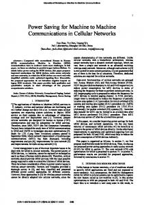
We have reviewed various flip-flops proposed in literature. Among these five flip-flops are chosen based on the possibility of implementation. The Table I shows the performance of these four flip-flops under consideration. A conventional SET flip-flop (Figure I) is triggered either at the rising edge or the falling edge of a clock cycle. In case of a rising SET flip-flop, the rising edge determines the output of the flip-flop. Similarly, in case of a falling SET flip-flop, the value of the input at the falling edge is transferred to the output port. However, for the correct operation of the flip-flop depends on, the input value has to be maintained constant just before (tset-up ) and just after (thold) the triggering edge of the clock. In SET D flip-flop (Figure 1) with 16 transistors [1,4], the Master section consists of a D latch which is functional on the positive level of the clock and transfers the logic level at input D to the intermediate node P. There is a feedback loop that maintains the logic level at the node P when the clock . INV�
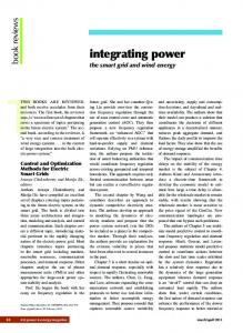
goes to logic level 'LOW'. Similarly, the Slave section consists of a D-Iatch, which is functional on the negative level of the clock and transfers the logic level at intermediate node P to the output node Q. Again, there is a feedback loop that maintains the logic level at node Q while clock is at logic level 'HIGH' state. Figure 2 shows a SET D Flip-flop using pass transistor. Even though it has fewer transistors but there is no much improvement in performance and in power consumption. In the negative edge triggered SETFF (Figure 3) even if the clock is stopped (permanently grounded) the circuit [5] is able to maintain the logic levels, which proves the fact that the this flop is static in nature. The main advantage of the circuit is the reduced transistor count, which is only ten. Hence, it can be used to increase the chip density while maintaining a lower manufacturing cost at the same time.
INVo INV2
INV�
-� � "
elK .elKt .
elK*,
Fig 2. SET Flip-Flop with Pass Transistor
Figure 1. Conventional SET D Flip-Flop with TG
elK
Q
ClK* INVI
N� '
INI'S
INV2
o
Figure 3. SET D Flip-flop proposed in [5]
978-1-61284-653-8/11/$26.00 ©2011 IEEE
Figure 4. Hybrid Flip-Flops
527
Proceedings of 2011 International Conference on Signal Processing, Communication, Computing and Networking Technologies (ICSCCN 2011)
TABLE I.
SIMULATION RESULTS OF SELECTED FLIP-FLOPS WITH TSMC 180NM CMOS TECHNOLOGY AT 1.8V
Tsu
Thold
TcIk-Q
Power
SET (PTL )
16
170.15
333.5
163.6
129.58p
12
190.25
325
360
1.228n
SET Prop
10
152.5
267.5
276
149.980
Hybrid
14
180.9
126.3
42.2
298.48p
Pulsed
8
NA
195.3
145.2
47.69p
#Tr
Flip-flop
SET (TG)
aos
(ps)
(ps)
(ps)
(W)
* T C&.p"., -57.1398 ps and T P""o-Q -87.9 ps
• setup time(ps)
400 300
• hold time(ps)
200 -HI--::I 100 o -t-LA.,.-.......---. ..
• tclk-q (ps) • power
dissipation (pW)
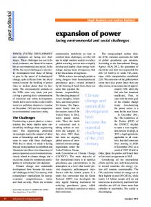
Figure 5. Comparative study of different flip-flops
Another topology is Hybrid FF (Figure 4). It is the fastest FF when compared all other flip-flops. But only disadvantage is that it consumes more power than convention FF. If power is not primary concern then Hybrid FF is the best choice for High Performance applications. The comparison on various metrics of all flip-flops discussed here are shown in Figure 5
III.
PROPOSED
SCAN FLIP-FL op
From Table I, Transmission gate - latch based flip-flops have low power application when speed is not a primary important. So these can serve for low power testing. Hybrid flip-flops are high speed flip-flops with relatively higher power consumption. So these have less scope in low power testing. Pulsed flip-flops are more attracted towards high speed and low power testing due to its negative setup time and due to less area occupied. Based on our evaluation, we desire to use pulsed flip-flop as scanned flip-flop. The proposed pulsed scan flip-flop in Fig. 8 consumes less power, occupies lower area while achieving higher performance compared to conventional muxed scan flip-flop cell (Figure 7).The layout of muxed scan flip-flop and pulsed scan flip-flops are given in Figure 9 and Figure 10 respectively. Traditionally, flip-flops are made up of a master-slave latch, with data being latched at the master and delivered to the slave at the sampling edge of the clock. Such an implementation has a positive setup time and has high figure of merit.
978-1-61284-653-8/11/$26.00 ©2011 IEEE
Figure a/merit
=
TCLK.q+Tsli
(1)
This figure of merit for a flip-flop added with the combinational logic delay determines the operating frequency of a design. The desire to reduce this figure of merit (Tcq+TslI) motivates to develop a pulse based flip-flop. A pulse generator circuit is shown in Figure 8(a). The pulse width can be easily controlled by appropriately sizing the inverters. In Figure 8(b), the latch becomes transparent for the short time duration in which the PULSE signal is high. The pulse is derived from the input clock edge and hence is generated after the clock edge. This allows the data to arrive later than the clock edge, hence making Tsu negative. This fact helps reduce the figure of merit. The pulse generator circuit can be shared across several flip-flops, amortizing its area and power cost. Mux based master-slave scan flip-flop has 28 transistors. This flip-flop is suitable for low power application when speed is not a primary important. So these can serve for low power testing. The proposed Pulsed scan flip-flop requires 12 transistor counts. As pulse occurs after clock triggers, there is no setup violation. The power consumption is less when compared to muxed SFF and can be used for high speed applications. So by using Proposed Pulsed SFF is more efficient for high speed and low power testing applications. POWER REDUCTION METHODOLOGY Power
IV.
dissipation in CMOS circuits consists of two types: dynamic power and static power. Dynamic power dissipation occurs during output switching because of short-circuit current, and charging and discharging of load capacitance, while static power dissipation is caused by leakage current or other current continuously drawn from the power supply. For CMOS technology, dynamic power is the dominant source of power dissipation. Dynamic power dissipation of CMOS circuit can be calculated as: PdynamIC .
=
2"lXCload
X
V�D X f X a
(2)
where C'oad is the load capacitance (including gate input and interconnect capacitances), f is the clock frequency, a is the expected number of output transitions in a cock period, and Vdd is the supply voltage of the circuit. From (2) we can see that, under given C'oad. VDD and f, which are usually decided by given technology and design, the most efficient and easy way to reduce dynamic power is to reduce the value of a, which has linearly correlation with the Pdynamic.
528
Proceedings of 2011 International Conference on Signal Processing, Communication, Computing and Networking Technologies (ICSCCN 2011)
VDD
INV2
Sl
o c:::::> ---+
PULS�
M�I Figure 6. Pulsed Flip-Flop
Figure 7. Mux Based Master-Slave Scan Flip-Flop
fI';'M
�Pll.SE I-f'>Pll.SE-
Figure 8(a). Pulse Generator VDD
3I
Figure 9. Layout ofMuxed scan Flip-Flop
D
Figure 8 (b). Proposed Pulsed scan Flip-Flop Figure 10. Layout ofproposed scan flip-flop
Scan-based testing schemes include two phases: shift and
performance metrics of Muxed Master-Slave scan flip-flop
capture, where capture cycles appear periodically among shift
and Pulsed scan flip-flop is carried at layout using IC Station
We mainly focus on to reduce power dissipation
layout designer tool with TSMC 180nm CMOS Technology
during shifting the sequence of vectors by scan cells, though instantaneous power dissipation during capture cycles are
is given in Table II. The area of Muxed scan FF is 124.859 2 2 um whereas area of pulsed scan FF is 93.774 um . The area
usually higher than that of shift cycles, the duration of shift
reduction of24.09% is achieved.
cycles.
mode is usually much longer than that of capture mode. The
978-1-61284-653-8/11/$26.00 ©2011 IEEE
529
Proceedings of 2011 International Conference on Signal Processing, Communication, Computing and Networking Technologies (ICSCCN 2011)
III-I
By using eldo simulator we have calculated the transition
S
powers (H----+L , and L----+H ). Table III gives the transition power of both scan FFs. The
frequency, rise/fall time and with F04 as load.
#Trans
flop
(3)
i)(bi $ bitl)
The average scan power dissipated during test application is by the
above
formula over all scan chains and all test patterns. The same rules apply to unload transitions observed when scanning out test responses.
The Table V presents the summary of the
Tsu
Thld\
Tclk-q
Power
( ps)
(ps)
(ps)
(pW)
experimental results which show that the proposed pulsed SFF inserted circuit can save �25% of the power when compare to
Muxed
28
145
126.37
181.75
201.44
Pulsed
18
NA
82.28
105.41
57.24
the conventional muxed SDFF.
VI.
T ABLE Ill. TRANSITION POWER MEASUREMENT AT 500MHz, 1.8V
CONCLUSION
The new pulsed SFF is presented in this paper for low
Type of Scan Flip-Flops
Transitions
-
obtained by summing up results provided
PERFORMANCE METRICS OF MUXED SCAN FF AND PROPOSED PULSED SCAN FF
Scan Flip-
2[m(m + l)J;=� (m
Table IV provides the the
performance analysis of various cases like varying the clock
T ABLE II.
=
MuxedScan FF n W
PulsedScan FF n W
OlEI
427.77
281.25
I lEO
213.99
212.50
power VLSI testing. This proposed scan FF not only saving the power and can also operate with higher speed. The area overhead due to pulse generator can be tolerated if it shares with multiple pulsed SDFF. This Pulsed SFF can be included into the standard cell library so that any timing violation
TABLE V.
EXPERIMENTAL RESULTS ON BENCHMARK CIRCUITS
# of
0/0
Testing power(uW)
itself
Power
Test
# of
Circuits
Vecto
Toggle
Muxed SFF
PulsedSFF
Reduc
S298
23
2158
1464.33
1112.66
24.01
S344
13
1379
980.30
740.13
24.4
S386
64
1189
884.38
660.260
25.34
rs
caused by this FF can be solved in the RTL synthesis level
REFERENCES
tion
[1]
Yu Chien-Cheng "Design of Low-Power Double Edge-Triggered Flip Flop Circuit "IEEE conference on industrial electronics and applications , vol. 34, No.3, pp.168-173, 2008.
[2]
V. Stojanovic and V. G. Oklobdzija, "Comparative analysis of master slave
latches
and
flip-flops
for
high-performance
and
low-power
systems," IEEE J. Solid-State Circuits, vol. 34, pp. 536-548, Apr. 1999.
[3] V.
[4]
Darwish,
and
M.
flip-flops.
Bayoumi.
The
Low
45 th Midwest
power
and
Symposium
high on
The test patterns generated b y
ATALANTA ATPG are applied t o proposed pulsed SDFF
Rasouli, S.H., Khademzadeh, A, Afrali-Kusha, A, and Nourani, M.," Low power single and double edge-triggered flip-flop for high speed applications," lEE Proc.-Circuits Devices Syst., Vol. 152, No. 2, April
pulsed scan flip-flop, experiments are conducted on full scan
2005.
[5]
Manoj sharma, Dr Arti Noor , Shatish Chandra Tiwari, Kunwar Singh ,
"An Area and Power Efficient design of Single EdgeTriggered D-Flip
based scan inserted netlist and muxed SDFF based scan
Flop",
inserted netlist.
2009
International
Conference
on
Advances
in
Recent
Technologies in Communication and Computing.
[6]
Symposium, San Diego, 2008, pp.147-154.
[7]
switching activity when applying test patterns produced b y
Proc. IEEE VLSI Test Symposium (VTS), May 2005, pp. 265-270.
[8]
and DFT Techniques", Proc. International Test Conference, Charlotte,
activity is estimated by the weighted transition metric (WTM)
2004, pp.355-364.
[9]
scan cells, while taking into account their relative positions. =
NBadereddine,
P.Girard,
S.Pravossoudovitch,
AVirazel,
and
C.
Landrault, "Scan Cell Reordering for Peak Power Reduction during Scan Test Cycles", IFIP Internatinal Federation for Information
blb2 ... bm
Processing, Vol. 240, VLSI-SoC:
represent a test vector with bit bk scanned in before bk+ 1. The normalized form of the metric is then defined as follows:
KM.ButIer, J .Saxena, AJain, T .Fryars, J .Lewis, and G.Hetherington, "Minimizing Power Consumption in Scan Testing-Pattern Generation
chains and other parts of the CUT. The resultant switching that counts the number of invoked transitions in successive
X Wen, Y. Yamashita, S. Kajihara, L.-T. Wang, K. K. Saluja, and K. Kinoshita, "On Low-Capture-Power Test Generation for Scan Testing,"
ATPG. Scan shift operations dissipate power which depends directly on the number of transitions that occur in the scan
Y.-Z.Wu, M.C.-T.Chao, "Scan-Chain Reordering for Minimizing Scan Shift Power Based on Non-Specified Test Cubes", Proc. VLSI Test
The primary focus of the experiments is to measure the amount of toggling, and to compare shifting power based on
Let m be the length of a scan chain, and T
T.
Circuits and Systems Conf, 11477 - 11480,2002.
In order to validate the effectiveness of the proposed ISCAS89 benchmark circuit.
P. Zhao,
speedexplicit-pulsed
EXPERIMENTAL RESULTS
From Systems
to
Silicon, 2007,
pp.267-28I
[10]
C. Shi and R. Kapur, "How Power Aware Test Improves Reliability and Y ield", IEEDesign.com, September 15, 2004.
[11]
Nicolici,N., A1-Hashimi,B.M.m "Power-Constrained Testing of VLSI Circuits ", Kluwer Academic Publishers, Dordrecht (2003) ISBN140207235-X 2003.
978-1-61284-653-8/11/$26.00 ©2011 IEEE
530
Proceedings of 2011 International Conference on Signal Processing, Communication, Computing and Networking Technologies (ICSCCN 2011)
[12]
[13]
M.
Pedram .
Power
minimization
in
IC
design:
Principles
and
[14]
D. Czysz, M. Kassab, X. Lin, G. Mrugalski, J. Rajski, J. Tyszer, "Low
applications. ACM Transactionson Design Automation of Electronic
Power Scan Shift and Capture in the EDT Environment" Internationa
Systems (TODAES), 1(1):3-56, January 1996.
Test Conference(ITC). 2008
K Roy and S. Prasad. Low-Power CMOS VLSI Circuit Design. John
Wiley & Sons, 2000. TABLE IV .
POWER DISSIPATION OF TGMS SCAN FLIP-FLOP AT 500MHZ AND 250MHz FOR D IFFERENT RISE &F ALL TIMES Rise & fall time
Frequency
Transitons
20% ofTC/k
15% ofTC/k
10% ofTC/k
5% ofTC/k
Peak
Average
Peak
Average
Peak
Average
Peak
Average
Power
Power
Power
Power
Power
Power
Power
Power
Muxed SDFF
OIEI
701.58
561.32
534.37
429.5
549.75
439.80
579.37
468.5
@500MHz
I lEO
426.66
341.33
460.125
368.1
497.71
397.73
613.12
490.5
Pulsed SDFF
OIEI
464.09
278.45
391.95
235.17
402.75
241.65
477.00
286.20
@500MHz
I lEO
742.63
445.57
859.5
512.37
888.75
533.25
962.00
481.50
Muxed SDFF
OIEI
544..33
435.46
536.25
426.60
388.12
296.87
534.37
374.06
@250MHz
I lEO
417.46
313.10
393.75
295.31
308.02
214.37
385.87
293.26
Pulsed SDFF
OIEI
425.06
261.45
441.76
287.14
479.25
277.96
420.75
260.86
@250MHz
I lEO
724.26
579.41
729.65
423.20
684.90
376.69
650.65
390.39
978-1-61284-653-8/11/$26.00 ©2011 IEEE
531