Refactoring Long Running Transactions: A Case Study Gianluigi Ferrari1 , Roberto Guanciale1 , Daniele Strollo1 , and Emilio Tuosto2
2
1 Dipartimento di Informatica, Universit`a degli Studi di Pisa, Italy {giangi,guancio,strollo}@di.unipi.it University of Leicester, Computer Science Department University Road, LE17RH, Leicester, UK
[email protected]
Abstract. Managing transactions is a key issue in Service Oriented Computing where particular relevance is given to the so called Long Running Transactions (LRT). Here, we show how to apply a formal approach to the specification and refactoring of LRT. Specifically, we consider a methodology arising on process calculi and show how it can be applied to a case study.
1 Introduction Service Oriented Computing (SOC) envisages systems as combination of basic computational entities, called services, whose interfaces can be dynamically published and bound. Abstract composition/coordination mechanisms are necessary as SOC systems are typically executed on overlay networks, namely inter-networked communication infrastructures (e.g., wired and wireless networks, telecommunication networks or their combination). Such abstract mechanisms are divided in to orchestration and choreography. Services are orchestrated when their execution work-flow is described through an “external” process, called orchestrator. A choreography specifies how services should be connected and interact so to accomplish the overall choreography goals. Roughly, choreographies yield an abstract global view of SOC systems that must eventually be “projected” on the distributed components. In this paper, we apply the theory defined in [4] to a case study taken from the S EN SORIA project [9]. More precisely, in [4] it is shown how Long Running Transactions (LRT) can be refactored in a semantially sound way, namely a few refactoring rules for LRT are given and proved to preserve (weak) bisimilarity. An original contribution of this paper is the description of our methodology via an implemented programming framework, called E SC, based on the process calculi used in [4]. Our methodology consists of the following steps: 1. the software architect designs the LRT model in a semiformal notation (in this paper we adopt BPMN [8,10]); 2. programmers produce an initial implementation of the model in S CL, the programming language featured by E SC; 3. the initial implementation is refactored by repeatedly applying refactoring rules that automatically transform the implementation in an equivalent one. M. Wirsing, M. Hofmann, and A. Rauschmayer (Eds.): TGC 2010, LNCS 6084, pp. 318–334, 2010. © Springer-Verlag Berlin Heidelberg 2010
Refactoring Long Running Transactions: A Case Study
319
The refactoring in the last step is applied according to the model-driven approach and allows the initial implementation to be adapted to choices/changes that may arise in a later stage of the development. For instance, the initial implementation can be given ignoring the execution platform; refactoring rules will then be applied to adapt the code to the underlying platform. Notice that this allows changes to the code to be done automatically for instance when the execution platform is decided or when it changes after the deployment. Remarkably, the adoption of the E SC framework relieves software architects and programmers from the intricacies of the theoretical background. The E SC framework and its theoretical foundation guarantee the correctness, namely that refactored S CL code is equivalent to the initial implementation. Synopsis. The E SC development framework on its underlying model are described in § 2; the S CL language is introduced in § 3; the S ENSORIA case study and the LRT refactoring rules are discussed in § 4; the action of the refactoring rules on S CL code is given in § 5; final remarks are in § 6.
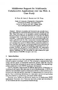
2 Background We summarise the main ingredients of our framework illustrated in Figure 1 where E SC (left block), SC (middle block), and NCP (right block) are respectively a programming platform, its underlying formal model, and the choreography model all relying on event notification as the basic coordination paradigm. The Event-based Service Coordination (E SC) platform provides a set of Eclipse plugins that offer a graphical and a textual representation of networks and is detailed below.
ESC Platform
Transactions
Saga
SCL / SCDesigner
Signal Calculus (SC)
SCL / SCDesigner
Signal Calculus (SC)
SCL / SCDesigner
Signal Calculus (SC)
- Conformance - Bisimulation - Choreography model NCP
Formal Model Refinement
Java Code Deployment
Implementation
Java Signal Core Layer
Model Transformation
Fig. 1. E SC architecture
320
G. Ferrari et al.
The Signal Calculus [5,3] (SC) yields a set of core primitives suitable and plays the key role of intermediate meta-model with respect to the other two layers. The calculus of Network Coordination Policies [1] (NCP) extends and equips our framework with a choreography model. In Figure 1, the arcs from SC to NCP represent the possibility to map SC models on NCP so that the conformance to SC designs can be verified. The E SC framework relies on J SCL (a set of Java API realising SC) and offers two different perspectives of the network. The graphical representation presents a global view of the choreography by considering the components and their interconnections, without detailing their internal logics. The textual notation offers a closer view of components allowing designers to focus on the behavioral aspects. In a model driven metaphor, the aspects treated at these different levels of abstraction share a common meta-model. In this way a level can be easily transformed into another so that the resulting target model can be used for automatically generating (executable) J SCL code. In fact, the E SC platform supplies a set of model transformation tools that, starting from the high level specifications (cf. blocks BPMN transactions and U ML 4S OA [11] in Figure 1), automatically build their corresponding representation in the S CL model. The event-notification model featured by S CL is based on components that asynchronously emit typed events; events are called signals and their types are called topics. A component may react to signals through reactions installed in their interface; each reaction has an associated behaviour executed when a signal triggering the reaction is received. Additionally, events are associated with sessions allowing to distinguish the different workflows. Intuitively, a session yields a “virtual communication link” among distributed components. Sessions are transparent to programmers and have a scope (i.e., the components participating in some interactions) that are dealt with by the S CL semantics. In other words, the semantics of S CL guarantees that components outside the scope of a session do not react to the events related to such session.
3 Signal Core Language The textual representation supported by E SC is the Signal Core Language (S CL) implemented as a textual plug-in for Eclipse1 . An S CL model defines a network by aggregation of components, described in terms of “reactive” software modules declaring the class of events they are interested to and the way they react at the occurrence of events. An example of S CL network is in Code 1.1 (where ellipses stand for immaterial code); the network consists of components a (LINES 3-20) and b (LINES 21-26). Topic names can be declared either restricted or ( LINE 1 and LINE 2). A component has to declare its intention to refer a restricted name using the declaration knows (e.g., a on LINE 6). Instead, global names can be referred by all components in the network. Moreover, topic names can be declared local (LINE 4) or during in the body of a component through the primitive with (LINE 17). Similarly, component names can be declared restricted by tagging components with the protected clause (LINE 21). 1
The textual editor has been implemented by using OpenArchitectureWare (oAW) [7], a modular MDA/MDD generator framework and supports code completion, error checking and code generation.
Refactoring Long Running Transactions: A Case Study
1 2 3 4 5 6 7 8 9 10 11 12 13 14 15 16 17 18 19 20 21 22 23 24 25 26
321
restricted: s1 , s2 ; global: t1 , t2 , t3 ; component a { local: lt1 , lt2 ; flows: [t1 ->a], [lt1 ->b ]; knows: s1 ,b; reaction lambda ( t1@ws ){ addFlow ([ ws ->b ]); addReaction ( reaction check ( lt1@lt2 ){ emit ( t1@lt1 ); } ); nop; do ... or ... split ... || ... with ( nlt1 ) ... skip ; } } protected component b { knows: s1 ; main { ... } }
Code 1.1: An S CL network of two components
Besides local names, components declare topics of their flows (LINE 5) and reactions. The flows of a component specify where the signals have to be routed (e.g., signals of topic lt1 emitted by a are rooted towards b). Reactions specify what signals a component can react to and the corresponding code to be executed upon reaction. There are two kind of reaction; a reaction lambda, activated for a topic regardless its related session, and reaction check, triggered only within a specific session. For instance, a reacts to any signal on topic t1 (LINE 7) while can react to signals on topic lt1 only if they are related to session lt2 (see LINE 10). The computational steps described inside reactions, declare their behaviors. The basic primitives are – emit (LINE 11), used to send out notification for an occurred event, – addFlow (LINE 8) and addReaction (LINE 9) that allow flows and reactions of a component to be dynamically updated, – nop (LINE 14) to indicate a block of code externally defined through host language instructions that do not interfere the coordination patterns (e.g. the access to the database), – skip (LINE 18) represents the empty action (the SC silent action).
322
G. Ferrari et al.
Furthermore, behaviors can be composed in sequence (using, as usual the semicolon) or with do-or (LINE 15) and split (LINE 16) constructs. The former constructs is used to implement the non deterministic execution of two branches, the latter allows the parallel composition of two behavioral activities. Notice that component b declares a main block (LINES 23-25) that specifies its initial behavior.
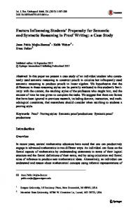
4 A Case Study: The Car Repair Scenario We apply our methodology to the S ENSORIA automotive case study [11] and show how it can be developed in the E SC framework. We briefly describe the case study. A car manufacturer offers a service that, once a user’s car breaks down, the system attempts to locate a garage, a tow truck and a rental car service so that the car is towed to the garage and repaired meanwhile the car owner may continue his travel. The following requirements are specified: – before any service lookup is made, an amount of money is reserved on the user’s credit card; – before looking for a tow truck, a garage must be found as it poses additional constraints to the candidate tow trucks; – if no tow truck is found, the garage booking must be revoked; – if a car rental (with an available car) is found succeeds while the search of either a tow truck or a garage fails, the car rental must be redirected to the broken down car’s actual location; – the failure of the search for a car rental should not affect the tow truck and garage booking. Such requirements impose the adoption of LRT as coordination with compensations is needed; also it is worth pointing out some peculiarities of the scenario. The application consists of different services that dynamically federate in order to provide new functionalities. Specifically, services (e.g., financial institutions, garages and car rental or taxi companies) team up to help the customer. This service composition is dynamic and cannot be anticipated in the code. Moreover, the scenario requires distributed transactional behavior to be dealt with. In fact, interactions among services can fail for many reasons and, of course, the customer should not be charged when the service cannot be provided. Finally, SOC systems usually have to be deployed on heterogeneous platforms and have to be executed on overlay computers, namely networks of many different kinds (e.g., wired networks, wireless ones or, telecommunication networks). For instance, the carrepair scenario requires software interfacing GPRS system, mobile phone, the Internet, and dedicated networks for financial transactions. The complexity of such applications requires in fact a rather sophisticated development methodology that can help programmers in facing the complexity of underlying and platform specific aspects. The LRT graphical model of this scenario is presented in Figure 2 (see Appendix A for an overview of LRT). The model exploits the transactional and compensation facilities of LRT; for instance, the car rental service is a sub-transaction, since (as required) it does not affect other activities.
Refactoring Long Running Transactions: A Case Study
Charge CreditCard
Order Garage Appointment
Revoke Charge
323
Order Tow Truck
Cancel Garage Appointment
Cancel Tow Truck
+
Order Rental Car
Redirect Rental Car
Fig. 2. Car repair scenario: the LRT model
Notice that initial design in Figure 2 simply describes the transactional aspects of the main activities. In this phase, it is not relevant to describe service distribution or (refined decomposition of the main activities). 4.1 LRT to S CL Model Transformation The E SC platform comes up with a set of tools that permit to transform the platform independent LRT models to the platform specific S CL models. The S CL implementation of transactional behaviors exploits two public names, f and r, respectively for forward and rollback events. Forward events propagate the successful completion from an activity to the next ones in the work-flow. Backward events are emitted on failures to trigger compensations. In the first step the model transformation generates an S CL component for every atomic process (aka an activity and the corresponding compensation). Subsequently, the model transformation can generate glue components and update the existing flows, however the behavior of components generated in the previous steps cannot be altered. This permits to transform a transactional process to an S CL network independently by the context, and reuse it as building block just changing its connections (S CL flows). The S CL snippets presented in the following contain unspecified behavior which is specific to the application (represented with comments in the code); this missing behaviours are supposed to be added by the programmers once the S CL code is compiled into J SCL API (e.g. Java). Atomic process. Figure 3(a) gives a pictorial intuition of the internal structure of atomic processes; Figure 3(b) illustrates a black-box view of atomic processes where solid (resp. dashed) arrows represent the forward (resp. backward) flow of LRT; finally, the sequential composition of a and b their forward and backward flows as in Figure 3(c).
324
G. Ferrari et al.
f
f
Main Activity
ex r
(b)
emit r
ok
install compensation & emit f
r
(a) Internal view of atomic process
(c)
Fig. 3. Atomic and sequential compensatable processes
In Code 1.2 we report the S CL coding of transactional activity G ARAGE where (according to Figure 3(a)) two private topics, ok and ex, (LINE 2) are declared so to be able to determine the termination of the main activity of the component. Notice that all events on topics ok and ex are delivered to G ARAGE itself (LINE 3). Initially the component can react only to f events (BLOCK 5-24). When reacting to forward events (signals on topic f), G ARAGE receives the session identifier s and execute the behavior corresponding to the LRT main activity (LINE 7). Such behavior is not explicitly
1 component garage { 2 local: ok , ex ; 3 flows: [( ok -> garage ), (ex -> garage ), 4 (r -> creditCard ), (f -> dispatcherPar )]; 5 reaction lambda ( f@s ) { 6 split { 7 /* coding of the main activity */ 8 do { emit ;} or { emit ;} 9 } || { 10 addReaction (reaction check ( ok@s ) { 11 split { 12 emit ; 13 }||{ 14 addReaction (reaction check ( r@s ) { 15 /* Compensation */ 16 emit ; 17 }); 18 } 19 }); 20 } || { 21 addReaction (reaction check ( ex@s ) { 22 emit ; 23 }); 24 } 25 }
Code 1.2: S CL compensatable activity
Refactoring Long Running Transactions: A Case Study
325
given, it is just assumed to issue an ok event on successful termination and send an ex event otherwise. Concurrently with the main activity G ARAGE installs a reactions to check when the main activity terminates (BLOCKS 10- 19 and 21-23). On successful termination (LINE 10), a signal on topic f is propagated (LINE 12) and a check reaction waiting for a possible rollback is installed (LINE 14-17); when a r event for the session s arrives, the activity is compensated (abstracted by nop on LINE 15) and the rollback signal propagated to previous stages ( LINE 16). If the execution of the activity fails (LINE 21), the handler simply starts the backward flow, raising a rollback event (LINE 22). Since the transformation of an atomic task generates only one S CL component, this component is both the entry point and the exit point of the generated network. Notice that the generated component has only flow to itself, since it is generated independently by the context. Parallel composition. The parallel composition of two LRT processes a and b is represented in Figure 4(a) where two additional components d and c represent the dispatcher and collector. A dispatcher propagates the forward flows to all the components executed in parallel and propagates the backward flows to the previous stage of the workflow. Similarly, the collector waits for the outcome of each parallel component before propating the forward flow and send rollback signals when subsequent stages of the workflow fail. The S CL code for dispatcher is Code 1.3 and 1.4, respectively. Such code is generated for the parallel composition of the T OW T RUCK and R ENTAL C AR services. The dispatcher (c.f. Code 1.3) represents the entry point of the parallel branch. Basically, it activates the forward flow of next components, and synchronizes their backward flows. Upon reactions to forward events (LINE 4), the collector emits two events: one having topic f (LINE 6) and the other one having topic n (LINE 8). The former event is delivered to the components representing the parallel activities. The latter event is delivered to the collector, informing it of the received session that will be later used by it to implement its synchronization. Concurrently, the collector activates its the synchronization mechanism by installing two nested reactions for the topic r in the work-flow session s (LINES 10 and 11). When the synchronization of the backward flow takes place, the emitter backwardly forwards the rollback event (LINE 12).
(a)
(b) Fig. 4. Parallel composition and transactional enclosure
326
G. Ferrari et al.
1 component dispatcherPar { 2 flows: [f -> towTruck ] ,[f-> dispatcherTrans ], 3 [r -> garage ] ,[n -> collectorPar ]; 4 reaction lambda ( f@s ) { 5 split { 6 emit ( f@s ); 7 } || { 8 emit ( n@s ); 9 } || { 10 addReaction (reaction check ( r@s ) { 11 addReaction (reaction check ( r@s ) { 12 emit ( r@s ); 13 }); 14 }); 15 } 16 } 17 }
Code 1.3: S CL parallel dispatcher
1 component collectorPar { 2 flows: [r -> towTruck ] ,[r -> collectorTrans ] ,[f - >...]; 3 reaction lambda ( n@s ) { 4 addReaction check ( f@s ) { 5 addReaction check ( f@s ) { 6 split { 7 emit ; 8 } || { 9 addReaction check ( r@s ) { 10 emit ; 11 } 12 } 13 } 14 } 15 } 16 }
Code 1.4: S CL parallel collector
Similarly, the collector component (in Code 1.4) is responsible to implement the synchronization mechanism for the forward flows (LINES 4 and 5) and to activate the backward flows of the parallel components when a r event is received (BLOCK 9-11). Once both the internal components have sent their forward messages, the collector sends out a f event (LINE 7). Notice that the collector exploits a n event to get information about the session s of the work-flow (LINE 3). After the generation of the new components, the flows of the two networks are updated (the flow for f in LINE 2). Moreover
Refactoring Long Running Transactions: A Case Study
327
the backward flow is suitable connected to the internal parallel components as given in LINE 2). The dispatcher and the collector components represent the entry and exit point of the parallel component, respectively. Isolated transaction. The intended meaning of transactional enclosure construct is that its internal failure does not affect other activities. For this reason, regardless the outgoings of a transactional activity a (see Figure 4(b)) the collector will receive a notification of forward event ( f ). The Not agent ensures that rollback requests from a are converted into forward requests so that the flow is passed to the next stages of the transaction. Conversely, if from the outside c receives a rollback, the component a must be informed and activate its compensation. Two cases are possible: i) a has previously successful terminated, so it has a compensation installed ii) a internally failed and no compensations are needed. On its turn, d has to consume two instances of r events before activating the backward flow while c, for the same session, consumes only a f event and ignores the further instances of f . Similarly to the parallel encoding previously exposed, the topic n is used from d to inform c that a new work-flow instance has been initiated so that the latter component can install the proper check reactions to consume two distinct instances of f events coming from a. The generated S CL code for the sub-transaction containing the R ENTAL C AR component is provided by three internal components according to the schema given in Figure 4(b). The DISPATCHERT RANS (c.f. Code 1.5) receives from the external activities the forward events (LINE 3), informs the COLLECTORT RANS that a new transactional session has been initiated (LINE 4), redirects the forward event to the R ENTAL C AR (LINE 5) and installs the rollback handler for the current session (BLOCK 6-10). Notice that, the rollback will be sent out (LINE 8) after the reception of two r notifications.
1 component dispatcherTrans { 2 flows [n -> collectorTrans ] ,[f -> RentalCar ]; 3 reaction lambda ( f@s ) { 4 emit ( n@s ); 5 emit ( f@s ); 6 addReaction (reaction check ( r@s ){ 7 addReaction (reaction check ( r@s ){ 8 emit ( r@s ); 9 }); 10 }); 11 } 12 }
Code 1.5: S CL transactional enclosure dispatcher
328
G. Ferrari et al.
1 component Not { 2 flows [f -> collectorTrans ]; 3 reaction lambda ( r@s ) { 4 emit ; 5 } 6 }
Code 1.6: S CL transactional enclosure not
The N OT port has the obvious meaning, it inverts the topic from r to f, without altering the session, as given in Code 1.6.
1 component collectorTrans { 2 flows: [f -> collectorPar ] ,[r -> RentalCar ], 3 [r -> dispatcherTrans ]; 4 reaction lambda ( n@s ) { 5 addReaction( reaction check ( f@s ) { 6 emit ( f@s ); 7 addReaction (reaction check ( r@s ) { 8 emit ( r@s ); 9 }); 10 }); 11 } 12 }
Code 1.7: S CL transactional enclosure collector The C OLLECTORT RANS (c.f. Code 1.7) waits until the dispatcher communicates the new working session (LINE 4). Consequently, it installs the handler for the f notifications coming from the R ENTAL C AR (BLOCK 5-10). Once received the f event it is delivered outside (LINE 6) and an handler for the rollback coming from the outside is installed (BLOCK 7-9).
5 Scl Model Refactoring In § 4.1 we have shown how to “compile” BPMN diagrams into S CL networks. Arguably, a similar mapping can be given also for other formalisms for LRT as [11]. Nevertheless, the automatically generated models may require some modifications either (i) to refine the code to consider those aspects not addressable in LRT (e.g., platform dependent issues) or (ii) to optimise the generated code. Figure 5 pictorially represents the structure of the coding automatically generated by S CL to be subsequently refined to better adhere to additional requirements that are
Refactoring Long Running Transactions: A Case Study
329
Fig. 5. A representation of the network generated in S CL
not taken into account at abstract level. For instance, the component distribution on the network, are not explicitly modeled at higher levels of abstraction, both at formal and specification levels. In fact, either LRT meta-models are not concerned with such aspects or, more pragmatically, they can more suitably considered at later stages of the development. For example, BPMN designs sketches how the overall transaction among transactional components should proceed without making any further assumption on which services implement such components (or where they are located). A possible solution to the problem described abovev is to refineme the code. The refinement process has to provide sound refactoring rules as those introduces in [4] and adopted here. Our translation of LRT into S CL models provides the suitable level of abstraction to which these refactoring steps can be applied. For example, deployment of distributed components or rearrangement of points of control can be automatically transformed at the S CL level respecting the original semantics of automatically translated designs. 5.1 Refactoring Transactional Components The first refactoring rule consists in delegating the compensation of S CL transactional components; the rule is applied to the G ARAGE (cf. Code 1.2, § 4.1). As already pointed out, both the main activity and the compensation of a transactional component are embedded into a single S CL component that manages ok and ex events in order to propagate forward or backward flows. However, it might be useful to delegate the compensation task to a different component. For example, the compensation should run on a different host than the main activity, because it involves a remote service. Usually, this aspect is not specified in the model of the business process. In the E SC framework, this issue can be tackled at deployment time, indeed implementation of J SCL [5] permits to orthogonally distribute components on the network topology. The refactoring rule generates a component, called C MP (Code 1.8, lines 20-29), that handles the compensation managing the backward flow and is reachable only by G ARAGE (line 5). For this reason, G ARAGE directs r and ex events as specified in the refactored set of flows (line 4). The refactored G ARAGE component needs only to check the termination of its main activity. In fact, its check reaction (line 9) propagates the
330
1 2 3 4 5 6 7 8 9 10 11 12 13 14 15 16 17 18 19 20 21 22 23 24 25 26 27 28 29 30 31
G. Ferrari et al.
restricted ex ; component garage { local: ok ; flows: [( ok -> garage ) ,( ex -> cmp ) ,(r -> cmp ) ,(f-> dispatcherPar )]; knows: cmp ; reaction lambda ( f@s ) { split { do { emit ;} or { emit ;} } || { addReaction (reaction check ( ok@s ) { split { emit ; }||{ addReaction (reaction check ( r@s ) { emit ; }); } }); } } protected component cmp { flows: [( r -> creditCard )]; reaction lambda ( ex@s ) { emit ; } reaction check ( r@s ) { /* Coding of Compensation. Defined by host language API. */ nop; emit ; } }
Code 1.8: Delegating compensation in S CL
forward flow and activates a listener for the rollback notifications possibly sent by subsequent transactional components. Notice that the reaction implicitly delegates the execution of the compensation to CMP. Once a rollback is captured by G ARAGE it is automatically forwarded to CMP according to the flows defined in line 4. Hence, CMP is informed if something goes wrong either during the execution of the main activity (ex events) or, after its successful execution, when r events is be delivered by other components. The component CMP waits the notification of an exception (line 7) or a rollback request coming from subsequent components. In the former case, CMP simply activates the backward flow while, in the latter case, CMP executes the compensation that, upon termination, starts the backward flow (lines 26-29).
Refactoring Long Running Transactions: A Case Study
n
n
r
f
f
r
r r
r
r
r
r
r
f
r
f
r
r f
f f
f
r
r
r
r
f
r
r f
r
r r
f
f
f
f
r
r
331
f
n
(a)
(b) Fig. 6. Parallel composition and its refactoring
5.2 Refactoring Parallel Composition The mapping of the parallel composition of transactions introduces two additional components, a dispatcher and a collector, respectively acting as the entry and exit point of the parallel composition. To illustrate the refactoring of parallel S CL transactions the scenario of § 4 is extended by adding a new activity (D ELAY) that informs the Information System of the driver company about a possible delay. This activity can be performed after G ARAGE has been contacted. Namely, the resulting business process contains three concurrent activities: the D ELAY, the T RACK and the sub-transaction that encloses R ENTAL C AR. Figure 6(a) depicts the flows and components required to implement this parallel composition. Two distinct dispatchers (D 1 and D 2) are involved in the coordination. Dispatcher D 2 is responsible to forward the received requests to components D ELAY and T RACK and results externally the entry point of their parallel composition. As result, the dispatcher D 1 is connected to the entry point of the sub-transaction R ENTAL C AR and to D 2, acting as entry point for the whole parallel block. Similar considerations can be made for the exit points C 1 and C 2. The notification of events to dispatchers D 1 and D 2 are not relevant to the semantic of the implementing network (more precisely these are hidden notification, since the dispatchers are not visible outside the network). The generation of two different dispatchers can provide a mechanism to optimize the communications among components. For example, if D 2, D ELAY, and T OW T RACK reside on the same host, the generated dispatcher permits to reduce the inter-host communications for the forward and backward flow, since it receives only one inter-host signal and generates two intra-host signals for D ELAY and T OW T RACK. If D ELAY, T OW T RACK, and R ENTAL C AR are remotely executed, the two dispatchers can be fused applying our next refactoring rule. Such rule can be applied in two directions, namely (i) it can merge two parallel dispatchers into one (simplifying the S CL code) or (ii) it can split a dispatcher into two parallel ones (refining inter-hosts communication). In the following we summarize the refactoring of parallel dispatchers.
332
G. Ferrari et al.
Noteworthy, the same strategy can provide a similar refactoring mechanism for the collectors. The refactoring merges the dispatcher D 2 with D 1 as follows: – Migrates any flow targeted to the dispatcher D 2 to the dispatcher D 1. For example, the flows of T OW T RACK becomes flows: [( ok -> TowTrack ) , ( ex -> TowTrack ) , (r -> RentalCar , Delay , d1 ) , (f-> c2 )]
– Add all flows of the dispatcher D 2 to the dispatcher D 1 (Code 1.9, line 2) – Removes the component D 2 – Extends the synchronization of D 1 in order to wait the reception of three rollback events (Code 1.9, line 10).
1 component D1 { 2 flows: [f -> Delay , TowTruck , dispatcherTrans ], 3 [r -> garage ] ,[n ->C1 , C2 ]; 4 reaction lambda ( f@s ) { 5 split { 6 emit ( f@s ); 7 } || { 8 emit ( n@s ); 9 } || { 10 addReaction (reaction check ( r@s ) { 11 addReaction (reaction check ( r@s ) { 12 addReaction (reaction check ( r@s ) { 13 emit ( r@s ); 14 }); 15 }); 16 }); 17 } 18 } 19 }
Code 1.9: Resulting dispatcher of the refactoring
6 Concluding Remarks Service manageability is a key issue that must be solved to widely adopt SOC. This paradigm can simplify software adaptation when changes in the business relations occur. However, the size of systems obtained by aggregating services can impose high costs possibly not affordable by small-medium enterprises. Of course, this may prevent SOA (service oriented architecture) to be largely adopted and limit its success. To reduce costs and the efforts of adopting SOA solutions, developers and designers should separately manage different aspects a system. This goal can be achieved by the adoption of the Model Driven Development. Framework and tools should provide
Refactoring Long Running Transactions: A Case Study
333
specific formalisms and languages suitable to manage a subset of the whole aspects of an application. We focused on the issues related to the management of transactional aspects of SOA systems. In the last years several toolkits have been developed to handle these specific issues (e.g. Eclipse/BPEL [2,12]). However, these proposals lack solid foundational grounds, making it difficult to provide reasoning techniques and to prove correctness of applications. In this paper we presented some of the main benefits provided by the strict interplay between theoretical results and programming practice. A key feature of our proposal is that any language involved by the development process has a formal description, allowing us to clearly define the semantics of systems and to provide sound tools. For example, our tool is equipped with refactoring rules that (i) support the designer in the refinement process (ii) do not affect the semantics of the system. We plan to adopt the same methodology to provide further extension to our framework. We want to investigate formal methods to manage different aspects of the system (e.g. quality of service). These models can drive the definition of domain specific languages that allow the developer to separately manage the corresponding domains.
References 1. Ciancia, V., Ferrari, G., Guanciale, R., Strollo, D.: Global coordination policies for services. ENTCS 260, 73–89 (2010) 2. Eclipse Modeling Framework, http://www.eclipse.org/modeling/emf/ 3. Ferrari, G.L., Guanciale, R., Strollo, D., Tuosto, E.: Coordination via types in an eventbased framework. In: Derrick, J., Vain, J. (eds.) FORTE 2007. LNCS, vol. 4574, pp. 66–80. Springer, Heidelberg (2007) 4. Ferrari, G.L., Guanciale, R., Strollo, D., Tuosto, E.: Refactoring long runing transactions. In: WSFM (2008) 5. Ferrari, G.L., Guanciale, R., Strollo, D.: Jscl: A middleware for service coordination. In: Najm, et al. [6], pp. 46–60 6. Najm, E., Pradat-Peyre, J.-F., Donzeau-Gouge, V. (eds.): FORTE 2006. LNCS, vol. 4229. Springer, Heidelberg (2006) 7. OpenArchitectureWare MDA/MDD generator framework, http://www.openarchitectureware.org/ 8. Business Process Modeling Notation (2002), http://www.bpmn.org 9. SENSORIA project, http://sensoria.fast.de/ 10. White, S.: Introduction to BPMN (May 2004), http://www.bpmn.org/Documents/Introduction%20to%20BPMN.pdf 11. Wirsing, M., Clark, A., Gilmore, S., H¨olzl, M.M., Knapp, A., Koch, N., Schroeder, A.: Semantic-based development of service-oriented systems. In: Najm, et al. [6], pp. 24–45 12. Wohed, P., van der Aalst, W.M., Dumas, M., ter Hofstede, A.H.: Pattern Based Analysis of BPEL4WS. Technical report, Department of Computer and Systems Sciences Stockholm University/The Royal Institute of Technology, Sweden (November 2003)
334
G. Ferrari et al.
A Overview of BPMN The graphical notation of BPMN permits to describe the work-flow of a distributed system by a global point of view. The software architect can abstract from the distribution of the processes, the communication mechanisms and the technologies that will implement each process. We focus on the transactional part of BPMN that in the following we indicate as LRT. Specifically, LRT encloses only the subset of BPMN necessary to model LRT. The basic elements of LRT are compensable activities, namely pairs of activities and compensations that can be composed sequentially or in parallel.
(a) Sequence
(b) Parallel
(c) Transactional scope
Fig. 7. Composition of compensable activities
Figure 7 depicts the designs respectively for sequential (a) and parallel (b) composition of compensable activities.Main activities and their compensations are represented as boxes linked by dashed arrows (for instance, Task1 has a ”compensation” entry point to which its compensation Comp1 is attached). The sequential composition is performed by linking together the main activities (cf. Figure 7(a)), while the parallel composition makes use of “fork” and “join” operators. In Figure 7(b) it is reported a parallel composition of two transactional activities. The two circles represent the start event and the end event of the whole process, while the diamond with the plus operation represents the join of the two parallel activities. The fork operation is implicit in the multiple connections on the start event. Finally, compensable activities, and their compositions, can be enclosed inside transactional boundaries as shown in Figure 7(c). All the elements presented at this layer are inherited from the core meta-models of BPMN and U ML 4S OA [11] and have the usual meaning of flowchart designs. Processes are built by composing activities as in Figure 7. BPMN does not specify the internal behaviour of activities and the interactions among components.