need is demonstrated by our experience with a relatively new Tektronix photometer, which was used to double- check the performance of our reference source.
Behavior Research Methods & Instrumentation 1981, Vol. 13 (1), 18-19
INSTRUMENTATION & TECHNIQUES Reference light source for luminance and illuminance photometry T. H. NILSSON University ofAlberta, Edmonton, Alberta T692EG, Canada The rationale for a constant source of both luminance and illuminance to check photometer calibration is discussed. The inexpensive construction of such a reference source is described, together with some performance data. Researchers in vision should consider maintaining some sort of reference light source for checking the calibration of photometers. Typical photometers have relative accuracies of ±2%/year and need periodic recalibration to assure that accuracy. By comparison, experienced observers in our laboratory have produced visual thresholds that are consistent to within .05 log over a 3-year span. Effort is required to ensure that light measurements are as stable as the visual system. This need is demonstrated by our experience with a relatively new Tektronix photometer, which was used to doublecheck the performance of our reference source. Recently, we found the internal calibration of the photometer to be in error by a factor of 3. A year earlier, the Tektronix instrument and our Spectra photometer agreed to within 2%. Standard light sources with calibrations traceable to the National Bureau of Standards (NBS) are ideal for checking the absolute accuracy of light measurements. However, there are alternatives if a standard source is not accessible and $900 is not available for purchasing a manufactured device such as the Spectra BSR·9B. When a recently calibrated photometer is available, the principle concern is insuring that its calibration has not changed. Determination of relative accuracy does not require a NBS standard light source; it requires only a constant source. An ordinary light bulb operated at exactly the same voltage for only a few minutes per year is very stable. For further information on standard light sources and photometry, consult Boynton (1966), Nicodemus (1977), and Rutgers (1971). In order to facilitate consistent use of a light bulb as a reference, the light bulb should be placed in an enclosure to eliminate extraneous light, and it should be well diffused so that exact aiming of the photometer is less critical. Since the ac power lines do not provide a consistent voltage, the lamp voltage should be adjustable using a variable transformer and monitored with an ac voltmeter, Reproducibility of the light depends primarily on the voltmeter. A voltmeter, plus effort, is Copyright 1981 Psychonomic Society, Inc.
substituted for an expensive, specialized, standard apparatus. (The considerably improved long-term stability of some 4.5·digit voltmeters compared with 3.5-digit models may well warrant their additional $100 cost for this purpose.) The method can produce a constant luminance that, for most applications, is just as adequate as a truly standard light source for checking photometer reliability. While luminance measurements are most desirable for specifying visual stimuli, luminance photometers are considerably more expensive than illuminance types. Illuminometers are more widely available and employed in engineering, architecture, and medicine. If the illuminance from a source of known visual angle can be measured, its luminance can be calculated with the formula: luminance = illuminance/rr sin2 (visual angle/2). Kietz (1971) provides a derivation of this equation.' An understanding of the relationship between luminance and illuminance should make it easier for persons without recourse to luminance photometers to provide proper specification of visual stimuli. A photodiode with CIE photopic response, a power supply, and a voltmeter are sufficient to make an illuminometer that may be incorporated into the optical system. Relatively inexpensive photographic light meters can also be used to measure illuminance. Table 1 shows how to convert photographic exposure readings into units of illuminance; the matter is further discussed by Long and Woo (1980). The response linearity of such devices can be determined with calibrated neutral density filters or with a movable light source relying on the inverse square law of distance and radiation. Since most illuminometers, except for the Macbeth, do not include a calibration source, a standardized illuminant is useful to check their absolute accuracy and stability. A constant luminance produces a constant illuminance at a given distance. For illuminance calibration purposes, the source should be spatially uniform and subtend a known solid angle. The known luminance must be the only source of light, and care must be taken to prevent 18
0005 -7878/81 /0 100 18.Q2$OO.45/0
REFERENCE LIGHT
19
Table 1 Converting Photographic Light Meter Readings Into Units of Illuminance Shutter Time 16 min Lumen/Meter'
.036
1 min .57
8 sec 4.3
1 sec 34
1/8 sec 276
1/125 sec 4.3 X 10
3
1/1000 sec 3.4 X 10'
Note- The above shutter times and illuminances are equivalent for a film speed of 100 ASA and an aperture setting off/4. The equivalent illuminance in lumens/meter' can be calculated from an equation based on the ASA film speed and the recommended exposure settings: lumen/meter' = (215.3 X [number? )!(ASA X shutter time in seconds). Glass Diffusing
Plates
Field
Slop
Stray Light
Baffles
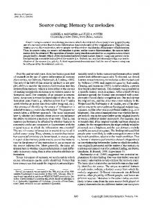
of 1.08 X 10³ cd/m? from a 5-deg visual field. Photometer readings of this reference light source have varied by less than 2% since 1977.
Photometer Positioning
Gate
All Surfaces
REFERENCES Exit Plane
120 VOAC
Figure 1. Schematic diagram for a reference light source to check luminance and illuminance calibrations of photometers.
stray light's reaching the photometer. A standard luminant can also serve as a standard illuminant by establishing a fixed distance for the photometer, defining the area of the source with a field stop, extending the lamp enclosure up to the photometer, and providing appropriate internal baffles. A combined reference for luminance and illuminance permits comparing the calibrations obtained with luminance photometers and illuminometers. When a photometer indicates a discrepant reading, it is reassuring to be able to measure the reference source with another device. Figure 1 shows a diagram of a reference source for luminance and illuminance that we have used for more than 3 years. The enclosure is made of plywood, and the field stop, baffles, and gate are of sheet metal. An 87.3-mm-diam field stop causes the source to subtend a 5-deg visual angle, or 5.98 X 10⁻³ steradians, at the 1-m distance of the photometer positioning gate. Tandem variable transformers facilitate precise adjustment of lamp voltage, which is read by a digital voltmeter. A 1Q0-W, 120-V, 3,000-h Westinghouse "Super Bulb" operated at 100 V produces a luminance of 1.03 X 1Q3 cd/m 2 as measured by our Photo Research "Spectra" photometer. Its l-deg measuring field detects less than a 2% variation in luminance across the field produced by the ground-glass diffusers. The illuminance at the gate is 6.46lm/m 2 as measured by our Weston "illumination Meter" Model 756. Using the above formula, this illuminance is equivalent to a luminance
R. M. Vision. In J. B. Sidowski (Bd.), Experimental methods and instrumentation in psychology. New York: McGraw-Hill,1966. KIETZ, H. A. E. Light calculations and measurements. London: Macmillan, 1971. LONG, W. F., & Woo, G. C. S. Measuring light levels with photographic meters. American Journal of Optometry and Physiological Optics, 1980,57,51-55. NICODEMUS, F. E. (Ed.). Self study manual on optical radiation measurements (National Bureau of Standards Technical Note 910). Washington, D.C: U.S. Government Printing Office, 1977. RUTGERS, G. A. W. Standards for photometry. Applied Optics, 1971,10,2595-2599. BOYNTON,
NOTE I. Provided that the stimulus being measured is the only source of light, its luminance (in candelas/meter' or lumens/ steradian/meter') can be calculated by dividing the illuminance (in lumens/meter') by its solid angle (in steradians). The order in which division is performed is immaterial. The principal hurdle is deriving the solid angle equivalent of a stimulus of known visual (plane) angle. Steradians of solid angle are defined as equal to the area subtended on a spherical surface divided by the square of the sphere's radius. Consider a circular stimulus of a certain visual angle. The distance of the stimulus is arbitrary and can be set equal to 1 m for convenience. From trigonometry, the radius of the stimulus equals the tangent of half the visual angle times the distance. The plane area of the stimulus equals pi times its radius squared: area = 11'[1 X tan(visual angle/2)j2. If the stimulus existed on a spherical surface instead of a plane, it would have to be slightly smaller in area in order to sub tend the same visual angle. (Think of the crimping required to make a bowl from a flat circle of paper.) The slightly smaller value of the sine provides an exact solution for spherical area compared with plane area: spherical area = n[l X sin(visuaI angle/2»), . Dividing this spherical area by the radius squared gives the solid angle: the expression is unchanged, since 1 m was chosen for the radius. Dividing the illuminance by this formula for the solid angle of a circular stimulus gives the equation presented in the text. Measurements of uniform noncircular stimuli can be accomplished by using a circular mask. (Received for publication October 8, 1980; revision accepted January 15, 1981.)