UNU-IIST International Institute for Software Technology
Refinement and Verification in ComponentBased Model Driven Design Zhenbang Chen, Zhiming Liu, Anders P. Ravn, Volker Stolz and Naijun Zhan November 2007
UNU-IIST Report No. 388
R
UNU-IIST and UNU-IIST Reports UNU-IIST (United Nations University International Institute for Software Technology) is a Research and Training Centre of the United Nations University (UNU). It is based in Macao, and was founded in 1991. It started operations in July 1992. UNU-IIST is jointly funded by the government of Macao and the governments of the People’s Republic of China and Portugal through a contribution to the UNU Endowment Fund. As well as providing two-thirds of the endowment fund, the Macao authorities also supply UNU-IIST with its office premises and furniture and subsidise fellow accommodation. The mission of UNU-IIST is to assist developing countries in the application and development of software technology. UNU-IIST contributes through its programmatic activities: 1. Advanced development projects, in which software techniques supported by tools are applied, 2. Research projects, in which new techniques for software development are investigated, 3. Curriculum development projects, in which courses of software technology for universities in developing countries are developed, 4. University development projects, which complement the curriculum development projects by aiming to strengthen all aspects of computer science teaching in universities in developing countries, 5. Schools and Courses, which typically teach advanced software development techniques, 6. Events, in which conferences and workshops are organised or supported by UNU-IIST, and 7. Dissemination, in which UNU-IIST regularly distributes to developing countries information on international progress of software technology. Fellows, who are young scientists and engineers from developing countries, are invited to actively participate in all these projects. By doing the projects they are trained. At present, the technical focus of UNU-IIST is on formal methods for software development. UNU-IIST is an internationally recognised center in the area of formal methods. However, no software technique is universally applicable. We are prepared to choose complementary techniques for our projects, if necessary. UNU-IIST produces a report series. Reports are either Research R , Technical T , Compendia C or Administrative A . They are records of UNU-IIST activities and research and development achievements. Many of the reports are also published in conference proceedings and journals. Please write to UNU-IIST at P.O. Box 3058, Macao or visit UNU-IIST’s home page: http://www.iist.unu.edu, if you would like to know more about UNU-IIST and its report series.
G. M. Reed, Director
UNU-IIST International Institute for Software Technology
P.O. Box 3058 Macao
Refinement and Verification in ComponentBased Model Driven Design Zhenbang Chen, Zhiming Liu, Anders P. Ravn, Volker Stolz and Naijun Zhan Abstract Modern software development has to deal with many different aspects and different views of applications. Thus it needs different modelling notations and tools to support more and more phases of the entire development process. To ensure the correctness of the models produced, the tools need to integrate sophisticated checkers, generators and transformations. A feasible approach to ensuring high quality of such add-ins is to base them on sound formal foundations. This paper summarizes our research on the Refinement of Component and Object Systems (rCOS) and illustrates it with experiences from the work on the Common Component Modelling Example (CoCoME). This gives evidence that the formal techniques developed in rCOS can be integrated into a model-driven development process and shows where it may be integrated in computer-aided software engineering (CASE) tools for adding formally supported checking, transformation and generation facilities. Keywords: Formal methods, multi-view modelling, rCOS, software design process, tool design, UML.
Zhenbangchen is a UNU-IIST fellow from the National Lab for Parallel and Distributed Systems, Changsha, China. He is working with Dr. Zhiming at UNU-IISt on formal methods of object and component systems, in Particular the rCOS method. His email address is
[email protected]. Zhiming Liu is a Research Fellow at UNU-IIST. His research interests include theory of computing systems, emphasising sound methods and tools for specification, verification and refinement of fault-tolerant, realtime and concurrent systems, and formal techniques for OO development. His teaching interests are Communication, Concurrent and Distributed Programming, Internet Security, Software Engineering, Formal specification and Design of Computer Systems. His email address is
[email protected] Anders P. Ravn is professor at Aalborg University, Denmark. He has been a close collaborator of Zhiming Liu for many years, and visited UNu-IIST twice in the past two years. Email:
[email protected]. Volker Stolz is postdoctoral research fellow, working with Dr. Zhiming Liu on the projects HighQSoftD and HTTS funded by Macau Science and Technology Fund. His research interest is in runtime verification, tools for design and verification, and formal methods of object and component software systems. Email:
[email protected]. Naijun Zhan is an associate professor at the Institute of Software of the Chinese Academy of Sciences. His research interest is in models of real-time systems, hybrid systems and coordination. He is currently visiting UNU-IIST and working with Dr. Zhiming Liu’s group on the model of coordination in rCOS. nj
[email protected].
c 2007 by UNU-IIST Copyright °
Contents
i
Contents 1 Introduction 2 Introduction to rCOS 2.1 Interfaces and contracts . . . . 2.2 A short introduction to UTP . 2.3 Class structures and datatypes 2.4 Contracts of interfaces . . . . . 2.5 Contract refinement . . . . . . 2.6 Consistency . . . . . . . . . . . 2.7 Components . . . . . . . . . . . 2.8 Simple connectors . . . . . . . 2.9 Coordination . . . . . . . . . .
1 . . . . . . . . .
. . . . . . . . .
. . . . . . . . .
. . . . . . . . .
. . . . . . . . .
. . . . . . . . .
. . . . . . . . .
. . . . . . . . .
. . . . . . . . .
. . . . . . . . .
. . . . . . . . .
. . . . . . . . .
. . . . . . . . .
. . . . . . . . .
. . . . . . . . .
. . . . . . . . .
. . . . . . . . .
. . . . . . . . .
. . . . . . . . .
. . . . . . . . .
. . . . . . . . .
3 4 5 6 7 8 9 9 10 10
3 Development process with rCOS 3.1 Requirements elicitation and modelling . . . . 3.2 Functionality Design . . . . . . . . . . . . . . 3.2.1 Functionality decomposition . . . . . . 3.2.2 Encapsulation . . . . . . . . . . . . . . 3.2.3 Class decomposition . . . . . . . . . . 3.3 Logical component-based architecture design 3.4 Detailed design and coding . . . . . . . . . . 3.5 Design of GUI and hardware controller . . . .
. . . . . . . .
. . . . . . . .
. . . . . . . .
. . . . . . . .
. . . . . . . .
. . . . . . . .
. . . . . . . .
. . . . . . . .
. . . . . . . .
. . . . . . . .
. . . . . . . .
. . . . . . . .
. . . . . . . .
. . . . . . . .
. . . . . . . .
. . . . . . . .
. . . . . . . .
. . . . . . . .
. . . . . . . .
. . . . . . . .
12 12 13 13 14 14 15 15 15
4 The Design of CoCoME 4.1 System overview . . . . . . . . . . . . . . . . . . . . . . . . . 4.2 CoCoME requirements modelling and analysis . . . . . . . . 4.2.1 Use case UC 1: Process Sale . . . . . . . . . . . . . . 4.2.2 Two more use cases . . . . . . . . . . . . . . . . . . . 4.2.3 Integrating the models and global constraints . . . . . 4.2.4 Discussion about requirements modelling and analysis 4.3 Design of the functionality of CoCoME by refinement . . . . 4.4 Logical component-based architecture of CoCoME . . . . . . 4.5 Detailed design of CoCoME . . . . . . . . . . . . . . . . . . . 4.6 Verification and analysis of the design . . . . . . . . . . . . . 4.7 Design of GUI and hardware controllers of CoCoME . . . . . 4.8 Tool support . . . . . . . . . . . . . . . . . . . . . . . . . . .
. . . . . . . . . . . .
. . . . . . . . . . . .
. . . . . . . . . . . .
. . . . . . . . . . . .
. . . . . . . . . . . .
. . . . . . . . . . . .
. . . . . . . . . . . .
. . . . . . . . . . . .
. . . . . . . . . . . .
. . . . . . . . . . . .
. . . . . . . . . . . .
16 16 17 18 24 26 26 27 32 35 39 40 41
5 Conclusions and Related Work
Report No. 388, November 2007
. . . . . . . . .
. . . . . . . . .
. . . . . . . . .
. . . . . . . . .
. . . . . . . . .
. . . . . . . . .
. . . . . . . . .
42
UNU-IIST, P.O. Box 3058, Macao
Introduction
1
1
Introduction
Software engineering is now facing two major challenges: • the rapidly increasing complexity of systems to be developed, and • higher demands for correct quality software. Thus we observe that software development is becoming complex due to many different but inter-related aspects or views of the system, including those of static structure, flow of control, interactions, and functionality, as well as issues about concurrency, distribution, mobility, security, timing, and so on. In addition to these problems in the design phases, the proper implementation of interactions among the GUI, the controllers of the hardware devices and the application software components is a demanding task. A most effective means to handle such complexity is separation of concerns; and assurance of correctness is enhanced by application of formal modelling and analysis. Separation of concerns is to divide and conquer. At any stage of the development of a system, the system is divided according to the concerns of the different views. These views can be modelled separately and their integration forms a model of the whole system. Different concerns require different models and different techniques; state-based static specification of functionality is good for specification and design of the functionality, while event-based techniques are the simplest for designing and analyzing interactions among different components. However, it is not easy to practice separation of concerns due to the following problems: 1. the lack of a design process which supports the identification of the crucial aspects of the system at different stages of the development and the design of the different aspects consistently, and 2. the lack of semantic foundation to define the precise relations among the different views that effectively supports a coherent and comprehensive understanding of the system, and because of this 3. the lack of integrated techniques and tools for consistent analysis and verification of the system. Analysis is needed, for example when one has to decompose a required “global” property into “local” properties of the different views. The suggested approach in practical software engineering to dealing with software complexities is component-based model-driven development (CB-MDD). With such an approach • the different aspects and views of the system are described in a UML-like multi-view and multi-notational language [38, 44],
Report No. 388, November 2007
UNU-IIST, P.O. Box 3058, Macao
Introduction
2
• separate design of the different aspects is supported by design patterns, object-oriented and component-based designs [27, 15], and • model construction is aided by UML-tools, design is supported by model transformation tools, and verification is supported mainly by testing tools. In this approach, the Rational Unified Process (RUP) [25] is often adopted. The practical engineering methods with CB-MDD in a RUP help to some extent by easing the problems in identification, modelling and design of the different views. However, to develop correct transformations and effective verification, there is need for a rigorous unified semantic theory and a coherent collection of high level theorems about the constructs, such that they support tool suites for specification, refinement and verification of the models. These are the main concerns of this paper. Rigorous specification, refinement and verification require the application of formal methods. In the past half a century, the formal method community has developed semantic theories, specification notations and tools of verification, including static analysis, model checking, formal proof and theorem proving, and runtime checking. They can be classified into the following frameworks: • event-based models [35, 21] are widely used for specification and verification of interactions, and they are supported by model checking and simulation tools [43, 12]. • pre-post conditions and Hoare logic are applied to specifications of functionality and static analysis; these are supported by tools of theorem proving, runtime checking, static checkers and testing [29, 13, 33]. • automata, state transition systems, and temporal logics are popular for specification and verification of dynamic control behaviors; they are supported by model checking tools [24, 28]. However, each framework is researched mostly by a separate community, and most of the research in verification has largely ignored the impact of design methods on feasibility of formal verification, automated verification in particular. Therefore, the verification techniques and tools are not very scalable and they are not easy to integrate into practical design processes. The notion of program refinement has obvious links to the practical design of programs with the consideration of abstraction and correctness, but the well-studied refinement calculi [36, 2] are shown to be effective for the correctness of program level functionality; but there is a need for extension to object-oriented and component-based model refinement as witnessed by the recent work on formal methods of component and object systems [4, 1, 3, 18, 8, 51]. In this paper, we present our ongoing research on a component-based design method, called rCOS. The method will include a modelling notation with a UML profile, defining concepts like
Report No. 388, November 2007
UNU-IIST, P.O. Box 3058, Macao
Introduction to rCOS
3
classes, objects, components, interfaces, contracts, coordination and composition. The method is founded on a well-studied semantic model with a refinement calculus [18, 8, 51], that is the basis from which to develop and integrate tools for model transformation and verification. We discuss how this method can effectively support the integration of the techniques and tools of refinement and verification in a component-based design process. In particular, we show in the CoCoME case study [10]: 1. what the models of the different aspects of the systems are at each stage of the development, including the requirements elicitation and modelling, functionality design by refinement, logical component-based architecture design, detailed design and coding, and design of GUI and hardware controllers, 2. how these models are constructed and derived by application of design patterns that are proved to be refinement in rCOS, and 3. how verification and validation tasks are identified for the models and what are effective tools for these tasks.
Outline In outline, the paper proceeds as follows. In Section 2 we give an overview of rCOS, showing how the significant concepts and artifacts of component-based software engineering are formalized in rCOS. This introduction tends to be informal and gives references to the literature where technical results are documented. This leads to a discussion in Section 3 about a software design process well integrated with rCOS. Section 4 is devoted to the rCOS development of the CoCoME case study, showing how rCOS is used for model construction and analysis with regard to the different design phases. The conclusions and related work are discussed in Section 5.
2
Introduction to rCOS
The research on rCOS develops a model driven development method that combines objectoriented and component-based design and analysis techniques. As a method, rCOS is founded on a formal semantic theory [18, 8]; it includes a modelling notation with a calculus of refinement for object-oriented models and component models [18, 8, 51]; also it considers integration with a development process, from requirements elicitation through to coding. Within a process, the formal techniques and tools of modelling, design and verification can be applied, such as MasterCraft [46] and ModelMorf [31, 11]. For these purposes, the rCOS semantic theory defines the important concepts and artifacts in the domain of object-oriented and component-based software engineering, like classes, objects, components, interfaces, contracts, composition (connectors), coordination and glue. It provides the behavioral semantics of these concepts with high level rules for refinement and verification.
Report No. 388, November 2007
UNU-IIST, P.O. Box 3058, Macao
Introduction to rCOS
4
Buffer put(T in ; )
Component
get(; T out)
Figure 1: A component with syntactic interface only
2.1
Interfaces and contracts
An interface I provides the syntactic type information for an interaction point of a component. It consists of two parts: the data declaration section, I.FDec, that introduces a set of variables with their types, and the method declaration section, I.MDec, that defines a set of method signatures. Each signature is of the form m(T1 in; T2 out), where T1 and T2 are type names, in stands for an input parameter, and out stands for an output parameter. We allow multiple input parameters and usually call the output parameter return. Current practical component technologies provide syntactical aspects of interfaces only and leave the semantics to informal conventions and comments. This is obviously not enough for rigorous verification and validation. For example, the component with only syntactic interfaces shown in Fig. 1 has no information about its functionality or behavior. For this, we define the notion of contracts of interfaces. A contract is a specification of the semantics for the interface. However, different usages of the component in different applications have different needs:
• An interface contract for a component in a sequential system is obviously different from one in a communicating concurrent system. The former only needs to specify the functionality of the methods, e.g. in terms of their pre- and post-conditions, whereas the latter should include a description of the communication protocol, e.g. in terms of interaction traces, to specify the order in which the interactions happen. • If the component is to be used in a real-time application, the contract of its interface must also specify real-time constraints, such as the lower and upper bounds of the execution time of a method. • Components in distributed, mobile or internet-based systems require the contracts of their interfaces to include information about their locations. • An interface (component) should be stateless when the component is required to be used dynamically and independently from other components.
Thus the rCOS framework takes great trouble to separate such concerns and viewpoints.
Report No. 388, November 2007
UNU-IIST, P.O. Box 3058, Macao
Introduction to rCOS
5
It is the contract of the interface that defines the external behavior and features of the component and allows the component to be used as a black box. Therefore in rCOS, we define an interface contract for a component as a description of what is needed for the component to be used in building and maintaining software systems. However, this description can be incremental in the sense that newly required viewpoints can be added when needed according to the application. Also, the consistency of these viewpoints should be formalizable and checkable. For this, rCOS builds on Hoare and He’s Unifying Theories of Programming (UTP) [23].
2.2
A short introduction to UTP
In UTP, a sequential program (but possibly nondeterministic) is represented by a design D = (α, P ), where • α denotes the set of state variables (called observables). Each state variable comes in an unprimed and a primed version, denoting respectively a pre- and a post-state value. The set includes program variables, e.g. x, x0 , and a designated Boolean variable, ok, ok0 , that denotes termination or stability of the program. • P is a predicate p(x) ` R(x, x0 ), defined as (ok∧p(x)) ⇒ (ok 0∧R(x, x0 )), meaning that if the program is activated in a stable state, ok, where the precondition p(x) holds, the execution will terminate, ok 0 , in a state where the postcondition, R, holds; thus the post-state x0 and the initial state x are related by relation R. It is proven in UTP that the set of designs forms a complete lattice with the logical implication, and true is the smallest (worst) element of the lattice. Furthermore, this lattice is closed under the classical programming constructs: • sequential composition, D1 ; D2 , • conditional choice, Dt C g(x) B Df , where g is a predicate, and Dt is selected when g evaluates to true, and Df is selected when g evaluates to false. • nondeterministic choice, D1 ∨ D2 , and • smallest fixed point of iterations, µx.D. All these constructs are monotonic operations on the lattice of designs. Refinement between designs is naturally defined as logical implications. These fundamental mathematical properties ensure that the domain of designs is a proper semantic domain for sequential programming languages. There is a nice link from the theory of designs to the theory of predicate transformers with the following definition: wp(p ` R, q) = b p ∧ ¬(R; ¬q)
that defines the weakest precondition of a design for a post condition q .
Report No. 388, November 2007
UNU-IIST, P.O. Box 3058, Macao
Introduction to rCOS
6
class attr method
.. . method invariant
C [extends D] { T x = d, . . . , T x = d m(T in; V return) { pre: p ∨ ... ∨ p post: ∧ (R; . . . ; R) ∨ . . . ∨ (R; . . . ; R) ∧ ...... ∧ (R; . . . ; R) ∨ . . . ∨ (R; . . . ; R) }/* method m */ .. . m(T in; V return) { . . . . . . } ...... Inv }
Figure 2: Specification of a class Semantics of concurrent and reactive programs, such as those specified by Back’s action systems [2] or Lamport’s Temporal Logic of Actions (TLA) [26], are introduced by the notion of reactive designs with an additional Boolean observable wait that denotes suspension of a program. A reactive design is written as g& P and defined by P C g B (true ` wait0 ), meaning that if the guard g is false, the program stays suspended, and if it is true, the result is P , where P is a design of the form H(p(x) ` R(x, wait0 )) = b (true ` wait0 ) C wait B (p ` R)
which means that execution will stutter until the program is no longer suspended. The domain of reactive designs enjoys the same closure properties as that of sequential designs, and also refinement is defined as logical implication [20].
2.3
Class structures and datatypes
Most, if not all, of the current component-based design and implementation techniques rely heavily on object-oriented techniques. For this, we allow the types of variables to be classes, and extend UTP with the notions of objects, classes, inheritance, polymorphism, and dynamic binding [19]. In rCOS, we write a class specification in the format of Fig. 2. An attribute is assumed to be public unless it is tagged with reserved words private or protected. The initial value of an attribute is optional; if no initial value of a class variable is declared, it will default to null. The precondition of a method is a disjunction of simpler predicates, and analogously the postcondition is a conjunction of simpler predicates. The reader can see the influence of TLA + [26], UNITY [7] and Java [16] on the above format. A design p ` R for a method is written as Pre p and Post R. An R in the postcondition is of the form c ∧ (le0 = e), where c is a condition, le an assignable expression and e an expression. An assignable expression le is either a variable x, an attribute name a or an indirect attribute name
Report No. 388, November 2007
UNU-IIST, P.O. Box 3058, Macao
Introduction to rCOS
7
le.a. An expression e may be a logically specified expression such as the greatest common divisor
of two given integers. We allow the use of indexed conjunction ∀i ∈ I : R(i) and indexed disjunction ∃i ∈ I : R(i) for a finite set I. Also, specifications of classes at a lower level design or even program code are allowed by using, together with designs, the usual object-oriented programming primitive commands and constructs. In rCOS, we distinguish data from objects and thus a datum, such as an integer or a boolean value does not have a reference. For this paper, we assume the elementary data types of V ::= long | double | char | string | boolean.
The types T are then generated by: T ::= V | C | set(T) | bag(T)
where C is a class name. We use the operations add(T a), contains(T a), delete(T a) on a set or a bag with their usual meaning. For a variable s of type set(T), the specification statement s.add(T a) equals s 0 = s ∪ {a}, and s.contains(T a) equals a ∈ s, and s.sumAll() is the sum of all elements of s, which is assumed to be a set of numbers. We use curly brackets {e1 , . . . , en } and square brackets [[e1 , . . . , em ]] to define a set respectively a bag. For a set s such that each element has an unique key or identifer, s.find(ID id) denotes the function that returns the element whose key equals id if there is one, or null otherwise. Notice that Java implements these types via the Collection interface. Therefore, these operations in specification statements can be easily coded in Java.
2.4
Contracts of interfaces
In the current version of rCOS, we consider components in the application of concurrent and distributed systems, and a contract Ctr = (I, Q, S, P) of interface I specifies • the allowable initial states by the initial condition Q, denoted by Ctr .Init, • the specification function S , denoted by Ctr .Spec, that assigns each method a guarded design g&D, and • the interaction protocol P , denoted as Ctr .Prot, which is a set of sequences of call events, where a sequence is written: ?op1 (x1 ), . . . , ?opk (xk ). Notice that a protocol can be specified by a temporal logic or a trace logic formula. We use Ctr .IF to denote the interface of contract Ctr .
Report No. 388, November 2007
UNU-IIST, P.O. Box 3058, Macao
Introduction to rCOS
8
Example 1 The component interface in Fig. 1 does not say that the buffer is a one-place buffer. A one-place buffer can be specified by a contract B1 for which • The interface: B1 .IF = hq : Seq(int), put(item : int; ), get(; res : int)i • The initial condition: B1 .Init = q = hi • The specification: B1 .Spec(put) = q = hi&true ` q 0 = hitemi B1 .Spec(get) = q 6= hi&true ` res0 = head (q) ∧ q 0 = hi
• The protocol: B1 .Prot is a set of traces that is a subset of {e1 , . . . , ek | ei is ?put(x) if i is odd and ?get(y) otherwise}. ¥
2.5
Contract refinement
A contract Ctr has a denotational semantics (cf. [20]) in terms of its failure set F(Ctr ) and divergence set D(Ctr ), that is the same as the failure-divergence semantics for CSP (but we do not use the CSP language) [8]. A contract Ctr 1 is refined by contract Ctr 2 , denoted by Ctr 1 v Ctr 2 , if the later offers the same provided methods, Ctr 1 .IF.MDec = Ctr 2 .IF.MDec, is not more likely to diverge than the former, D(Ctr 1 ) ⊇ D(Ctr 2 ), and not more likely to deadlock than the former, F(Ctr 1 ) ⊇ F(Ctr 2 ). We have established in [20] a complete proof technique of refinement by simulation. Theorem 1 (Refinement by Simulation) Ctr 1 v Ctr 2 if there exists a total mapping relating the observables u of Ctr 1 to the observables v 0 of Ctr 2 , denoted ρ(u, v 0 ) : Ctr1 .IF.MDec −→ Ctr2 .IF.MDec, such that 1. Ctr 2 .Init ⇒ (Ctr 1 .Init; ρ). 2. ρ ⇒ (guard1 (op) = guard2 (op)) for all op ∈ Ctr1 .IF.MDec, where guardi (op) denotes the guard of operation op in Ctr i . 3. for each op ∈ Ctr 1 .IF.MDec, Ctr 1 .Spec(op); ρ v ρ; Ctr 2 .Spec(op).
¥
Similarly, contract refinement can also be proved by a surjective upward simulation [8]. Theorem 2 (Completeness of Simulations) If Ctr 1 v Ctr 2 , there exists a contract Ctr such that Ctr 1 ¹up Ctr ¹down Ctr 2 . ¹up and ¹down denote upwards and downwards simulation, respectively.
Report No. 388, November 2007
¥
UNU-IIST, P.O. Box 3058, Macao
Introduction to rCOS
2.6
9
Consistency
The formalization of contracts supports separation of views, but the different views have to be consistent. A contract Ctr is consistent, denoted by Cons(Ctr ), if it will never enter a deadlock state when its environment interacts with it according to its protocol, that is, for each trace in the protoco h?op1 (x1 ), . . . , ?opk (xk )i ∈ Ctr .Prot, we have wp
µ
Init;g1 &D1 [x1 /in1 ]; . . . ; gk &Dk [xk /ink ], ¬wait ∧ ∃op ∈ Ctr .IF.MDec•g(op)
= true
Note that this formalization takes both synchronization conditions and functionality into account, as an execution of a method with its precondition falsified will diverge and a divergent state can cause deadlock too. We have proven the following theorem of separation of concerns [20]: Theorem 3 (Separation of Concerns) For i ∈ {1, 2} 1. If Cons(I, Q, S, Pi ), then Cons(I, Q, S, P1 ∪ P2 ) 2. If Cons(I, Q, S, P1 ) and P2 ⊆ P1 , then Cons(I, Q, S, P2 ) 3. If Cons(I, Q, S, P) and S v S1 , then Cons(I, Q, S1 , P). v stands for the pointwise extension of the refinement relation over (guarded) designs to mapping
functions.
¥
This allows us to refine the specification and the protocol separately.
2.7
Components
A component is an implementation of a contract. Formally speaking, a component is a tuple C = (I, Q, MCode, PriMDec, PriMCode, InMDec), where • I is an interface, called the provided interface and denoted by C.pIF, • Q is an initialisation command, denoted by C.Init, setting the initial values of the attributes, • MCode, denoted by C.MC, and PriMCode, denoted by C.PriC, map a public method and a private method m respectively to a guarded command gm → cm , • InMDec is the set of required methods used by the code of the component, called the required interface and denoted by C.rIF.
Report No. 388, November 2007
UNU-IIST, P.O. Box 3058, Macao
Introduction to rCOS
10
The semantics [[C]] is a function that calculates a general contract for the provided interface from any given contract InCtr of the required interface [[C]](InCtr) = b ((I, Q, S), PriMDec, PriMSpec)
It is a contract with the specification of the private methods, where the specifications S and PriMSpec are calculated by the semantic definition of the code, following the calculus established in UTP. A component C1 is refined by another component C2 , denoted by C1 v C2 if 1. they provide the same methods, C1 .pIF.MDec = C2 .pIF.MDec 2. they require the same methods C1 .rIF = C2 .rIF, and 3. for any given contract of the required interface (called an input contract), the resulting provided contract of the latter refines that of the former, C1 (InCtr) v C2 (InCtr), for all input contracts InCtr. Note that the notion of component refinement is useful for both component correctness by design and component substitutability in maintenance.
2.8
Simple connectors
To support the development activity, the semantic framework also needs to define operators for connecting components, resulting in new components, constructs for defining glue processes, and constructs for defining processes. In summary, the framework should be compositional and support both functional and behavioral specification. In rCOS, simple connectors between components are defined as component compositions. These include plugging (or union), service hiding, service renaming, and feedback. These compositions are shown in Figs. 3-5. put put
get1 C1
get C2
put1
get C1
get C1
C2
C2
put1 put1
Figure 3: Plugging
2.9
put
put1
put1
put1
Figure 4: Hiding
Figure 5: Feedback
Coordination
Components provide a number of methods, but do not themselves activate the functionality specified in the contracts; we need active entities that implement a desired functionality by
Report No. 388, November 2007
UNU-IIST, P.O. Box 3058, Macao
Introduction to rCOS
11
coordinating sequences of method calls. These active entities are specially designed for a given application and therefore do not in general share the defining features of components [45, 17]. To cater for this, we introduce in [8] process components, or simply processes, into rCOS. Like a component, a process has an interface declaring its local state variables and methods, and its behavior is specified by a process contract. Unlike a component that is passively waiting for a client to call its methods, a process is active and has its own control on when to call out to required methods or to wait for a call to its provided methods. For a process, we cannot have separate contracts for its provided interface and required interface, because we cannot have separate specifications of outgoing calls and incoming calls [17]. So a process just has a interface and its associated contract (or code). For simplicity, but without losing expressiveness, we assume a process like a Java thread does not provide methods and only calls methods provided by components. Therefore, processes only communicate via shared components. Of course, a component can also communicate indirectly with another component via processes, but without knowing the component with which it is communicating. Let C be the component, that is formed by disjoint union of a number of disjoint components C i , i = 1 . . . k . A coordination program for C is a process P that calls a set X of provided methods of C . The composition CkX P of C and P is defined similarly to the alphabetized parallel composition in CSP [43] with interleaving of events. The coordination composition is defined by hiding the synchronized methods (i.e. making them τ events) between the component C and the process P, that is (CkX P )\X and denoted as (Ck[X] P ). Inspired by the work of Woodcock and Morgan [48], we have proven in [8] that (Ck[X] P ) is a component, and studied the algebraic laws of the composition of processes and components. The coordination composition is illustrated in Fig. 6, where in Fig. 6(a) C1 and C2 are two one-place buffers and P is a process that keeps getting the item from C1 and putting it to C2. In Fig. 6(b), the get of C1 and put of C2 are synchronized into an atomic step by component M ; and M provides method move(){get1(; y); put2(y; )}, that process P calls. This shows that a coordinating process also plays the role of a glue code in building new components from given components. put 1
put
get C1
C1
get 1
C2
get 2
C2
put 2 M move
get1
(a)
put1 P
(b)
P
Figure 6: (a) Gluing two one-place buffers with a process forms a three-place buffer, (b) Gluing two one-place buffers forms a two-place buffer An application program is a set of parallel processes that make use of the services provided by components. As processes only interact with components via the provided interfaces of the components, interoperability is thus supported by the contracts which define the semantics of the common interface description language, even though components, glue programs and application
Report No. 388, November 2007
UNU-IIST, P.O. Box 3058, Macao
Development process with rCOS
12
programs are not implemented in the same language. Analysis and verification of an application program can be performed in the classical formal frameworks, but at the level of contracts of components instead of implementations of components. The analysis and verification can reuse any proved properties about the components, such as divergence freedom and deadlock freedom without the need to reprove them.
3
Development process with rCOS
With the rCOS models of the concepts and artifacts in component-based model-driven software engineering, we can accommodate a use-case driven, incremental and iterative Rational Unified Development Process [25]. Each iteration goes through the phases of requirements elicitation and modelling, functionality design, logical component-based architecture design, detailed design and coding and design of GUI and hardware controllers. Analysis and verification are carried out on the models produced in each of these phases.
3.1
Requirements elicitation and modelling
In the requirements elicitation and modelling, a number of use cases are captured, modelled and analyzed. Each use case is modelled as a contract of a component with a provided interface to the actors of the use case. The attributes of the interface declare the domain objects involved in the realization of the use case. The classes of these objects are organized as a conceptual class diagram1 that can be translated to a list of rCOS class declarations, representing the structural view of the data and objects of the components. The interaction protocol of the contract describes the interactions between the actors and the system for this use case. They are graphically represented as a UML sequence diagram called a use case sequence diagram. The flow of control and synchronization is modelled by a UML state diagram and the static functionality of interface methods is given in terms of their pre and post conditions. The combination of the state diagram and the static functionality specification is a reactive design for the contracts [9]. The contracts should be analyzed to ensure their consistency and desirable properties such as safety and liveness. The contracts of the use cases form the initial architecture of the system. 1
This term is borrowed from [27] and it is said to be conceptual, because the classes do not have the methods defined.
Report No. 388, November 2007
UNU-IIST, P.O. Box 3058, Macao
Development process with rCOS
3.2
13
Functionality Design
This phase focuses on the design of the functionality of the use case contracts using the OO refinement calculus [18], component refinement and substitution [8] in rCOS. This is mainly to refine the interactions between the actors and the system specified in the contracts of the use cases into interactions among the objects of the classes in the class diagram. There are three kinds of OO refinements involved: functionality decomposition, attribute encapsulation, and class decomposition.
3.2.1
Functionality decomposition
Assume that C and C1 are classes, C1 o is an attribute of C and T x is an attribute of C1 . Let m(){c(o.x0 , o.x)} be a method of C that directly accesses and/or modifies attribute x of C 1 . Then, if all other variables in the method c are accessible in C1 , we can refine C and C1 by changing m(){c(o.x0 , o.x)} to m(){o.n()} in class C and adding a fresh method n(){c[x0 /o.x0 , x/o.x]} in C1 . This is also called the expert pattern of responsibility assignment. This rule and other refinement rules in rCOS can prove big-step refinements, such as the following expert pattern, that will be repeatedly used in the design of the system. Theorem 4 (Expert Pattern) Given a list of class declarations Classes and its navigation paths le = b r1 . . . . .rf .x, {a11 . . . . .a1k1 .x1 , . . . , a`1 . . . . .a`k` .x` }, and {b11 . . . . .b1t1 .y1 , . . . , bs1 . . . . .bsts .ys } starting from class C, let m() be a method of C specified as C ::
m(){ ∧
c(a11 . . . . .a1k1 .x1 , . . . , a`1 . . . . .a`k` .x` ) le0 = e(b11 . . . . .b1t1 .y1 , . . . , bs1 . . . . .bsts .ys ) }
Then Classes is refined by redefining m() in C and defining the following fresh methods in the corresponding classes:
T(aij ) ::
check(){return0 =c(a11 .get πa x1 (), . . . , a`1 .get πa x` ())} 11 `1 m(){if check() then r1 .do-mπr1 (b11 .get πb y1 (), . . . , bs1 .get πb ys ())} s1 11 get πa xi (){return0 =aij+1 .get πa xi ()} (i : 1..`, j : 1..ki − 1)
T(aiki ) ::
get πa
T(ri ) :: T(rf ) :: T(bij ) ::
do-mπri (d11 , . . . , ds1 ){ri+1 .do-mπri+1 (d11 , . . . , ds1 )} (i : 1..f − 1) do-mπrf (d11 , . . . , ds1 ){x0 = e(d11 , . . . , ds1 )} get πb yi (){return0 =bij+1 .get πb yi ()} (i : 1..s, j : 1..ti − 1)
T(biti ) ::
get πb
C ::
ij+1
ij
x (){return iki i
0
ij+1
ij
iti
=xi } (i : 1..`)
yi (){return
0
=yi } (i : 1..s)
where T(a) is the type name of attribute a and πvi denotes the remainder of the corresponding navigation path v starting at position i. ¥ This pattern represents that a computation is realized by obtaining the data that is distributed in different objects via association links and then delegating the computation tasks to the target
Report No. 388, November 2007
UNU-IIST, P.O. Box 3058, Macao
Development process with rCOS
14
object whose state is required to change. If the paths {a11 . . . . .a1k1 .x1 , . . . , a`1 . . . . .a`k` .x` } have a common prefix, say up to a1j , then class C can directly delegate the responsibility of getting the x-attributes and checking the condition to T(aij ) via the path a11 . . . . .a1j and then follow the above rule from T(aij ). The same optimization can be applied to the b-navigation paths. The expert pattern is the most often used refinement rule in OO design. One feature of this rule is that it does not introduce more couplings by associations between classes into the class structure. It also ensures that functional responsibilities are allocated to the appropriate objects that know the data needed for the responsibilities assigned to them.
3.2.2
Encapsulation
The encapsulation rule says that if an attribute of a class C is only referred to directly in the specification (or code) of methods in C, this attribute can be made a private attribute; and it can be made protected if it is only directly referred in specifications of methods of C and its subclasses. We should note that data encapsulation may have to be applied after it is known that new classes introduced in later iterations do not need direct access to or extend the classes of the current iteration.
3.2.3
Class decomposition
During an OO design, we often need to decompose a class into a number of classes. For example, consider classes C1 :: D a1 , C2 :: D a2 , and D :: T1 x, T2 y . If methods of C1 only call a method D :: m(){...} that only involves x, and methods of C2 only call a method D :: n(){...} that only involves y , we can decompose D into two classes D1 :: T1 x; m(){...} and D2 :: T2 y; n(){...}, and change the type of a1 in C1 to D1 and the type of a2 in C2 to D2 . There are other rules for class decomposition in [19]. An important point here is that the expert pattern and the rule of encapsulation can be implemented by automated model transformations. In general, transformations for structure refinement can be aided by transformations in which changes are made with a graphical editing tool and then automatic transformation can be derived for the change in the specification of the functionality and object interactions. For details, please see our work in [51]. The final model to be produced at the end of the OO design of a use case is a contract in which the use case sequence diagram is refined to an object sequence diagram with inter-object interactions but with the events of interactions between the actors and the system unchanged, the conceptual class diagram refined to a design class diagram in which methods and their specifications are assigned to classes. The correctness of this design model is guaranteed by the correct use of the refinement rules.
Report No. 388, November 2007
UNU-IIST, P.O. Box 3058, Macao
Development process with rCOS
3.3
15
Logical component-based architecture design
In this phase, models of “small use cases” are organised into bigger components by using the union connector, and models of “large use cases” are decomposed into smaller interacting components according to the nature of the objects, such as their physical locations and roles that they play in the overall business organization. The interfaces among these components are identified from the object sequence diagrams of the use cases in the design model. The resulting model is called the model of the logical component-based architecture. The design decisions on (de)composition cannot be completely formalized or automated, but once a decision is made the construction of the logical component-based architecture from the design model can be automated by model transformations. The model includes a set of components with explicitly specified provided and required interfaces. They can be depicted by a UML component diagram, a component sequence (or interaction) diagram, and a state diagram for each (non-trivial) component. For this model, the compatibility of the contracts for the provided and required interfaces of the inter-dependent components should be checked to avoid deadlock and livelock. This is called the logical model because the interfaces of the components are all object-oriented interfaces in which component interactions are direct method invocations via object references.
3.4
Detailed design and coding
The detailed design activities include further refinement of the components by class decomposition, data encapsulation and refactoring; and replacement of some of the object-oriented interfaces with concrete and appropriate interaction mechanisms (or middlewares) such as RMI, CORBA or shared event channels. This transforms the platform independent model (PIM) of the logical component-based architecture to a platform specific model (PSM) with regards to the interaction mechanisms. Code can be constructed for each component. For this, a template of the code of each component can be generated from the detailed design of the components. The template includes the information of the flow of method invocations and the assertions specifying the functionality of the methods of the components. The flow of method invocations and assertions is derived and documented during the refinements of the design process. Such a code template is thus similar to a Spec] [34] or JML program [29]. Verification and validation can be applied to components before and after introducing the concrete middlewares, such as runtime checking, testing (unit testing) [29] and even by a verifying compiler [34, 22].
3.5
Design of GUI and hardware controller
Most software systems nowadays have components of GUI and hardware controllers that interact with the application software components. Some GUI objects and hardware controllers are only relevant to some use cases and their design can thus be given after the design of these use cases. Others, such as a printer, interact with the components of many use cases and therefore they and those GUI and hardware controllers that interact with them should be designed after the design
Report No. 388, November 2007
UNU-IIST, P.O. Box 3058, Macao
The Design of CoCoME
16
of all the components. It is important to note that design and analysis of the GUI components and hardware controllers can be done in a purely event-based model following the theory of embedded system design. The rCOS method supports the construction and analysis of such a model.
4
The Design of CoCoME
The case study of CoCoME is a trading system and extends the running example in Larman’s textbook [27], originally called the Point of Sale (POS) system. In this section, we apply rCOS with the development process described in the previous section to the design of this system, focusing on one iteration. Subsequent iterations would add more functionality to this core.
4.1
System overview
The trading system is a computerized system typically used in a supermarket. It deals with the various aspects of sales and other business processes, including processing sales at a cash desk and handling both cash and credit card payments, as well as updating the sales at the inventory. Furthermore, the trading system deals with ordering goods from product suppliers (or wholesalers), and generating various kinds of reports for management purposes.
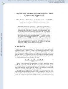
Figure 7: Overview of the entities of a cash desk (taken from [42])
At the cash desk, the customer can check out the products he wants to buy and make the payment. To do this the cashier records each product by entering the bar code with the bar code scanner or the keyboard. Furthermore, we introduce an express checkout for customers with only a few items in order to speed up handling customers. A cash desk, shown in Fig. 7, consists of the following devices:
Report No. 388, November 2007
UNU-IIST, P.O. Box 3058, Macao
The Design of CoCoME
Figure 8: Overview of a store
17
Figure 9: Overview of an enterprise
• a Cash Box with keys for starting and finishing a sale, entering received money and paying out changes, • a Bar Code Scanner with which product code can be scanned, • a Card Reader for handling credit card payment, • a Printer for printing the receipt at the end of the sale process, • a Light Display which signals whether the cash desk is in express mode, • a Cash Desk PC that integrates the hardware devices and runs the software handling the sale process and communication with the back office and clearing credit card transactions with the Bank.
The system can be a large system in which the store has a number of cash desks, called the cash desk line for checking out customers in parallel, or even a network of stores, each having a cash desk line, to support a whole enterprise. Each store has its own Store Server and Store Client for the store management, and each cash desk of the store is connected to its Store Server (see Fig. 8). In the case of a network of stores, there is need for an Enterprise Server and an Enterprise Client for enterprise management, and all stores are connected to the Enterprise Server (see Fig. 9). We consider the development of a system that is used in one store, but it has a number of checkout points. It thus includes hardware components such as bar code scanners, card readers, printers, and a software to run the system. To handle credit card payments, orders and delivery of products, we assume a Bank and a Supplier that interact with the system.
4.2
CoCoME requirements modelling and analysis
The system overview and problem description provide the initial context and vocabulary for further requirements elicitation through studying the business processes. The requirements analysis and system design are use-case driven. A use case specifies how the system interacts
Report No. 388, November 2007
UNU-IIST, P.O. Box 3058, Macao
The Design of CoCoME
18
with actors and its environment in realizing a business process. An actor, such as a Cashier who checks out customers, interacts with the system by calling a system operation to request a service of the system. There can be many use cases, depending on what business processes the client wants the system to support. In the following subsections, we work out the model of the use cases that we are concerned with in this paper.
4.2.1
Use case UC 1: Process Sale
One of the main use cases is processing sales, the use case UC 1: Process Sale.
Informal description of UC 1 The normal courses of interactions between the actors and the system are informally described as follows. 1. When a customer comes to the cash desk with her items, the cashier initiates a new sale. 2. The cashier enters each item, either by typing or scanning in the bar code; if there is more than one of the same item, the cashier can enter the quantity. The system records each item and its quantity and calculates the subtotal. When the cash desk is operating in express mode, only a predefined maximum number of items can be entered. 3. When there are no more items, the cashier indicates to the system end of entry. The total of the sale is calculated. The cashier tells the customer the total and asks her to pay. 4. The customer can pay by cash or credit card. If by cash, the amount received is entered. The system records the cash payment amount and calculates the change. If by credit card, the card information is entered. The system sends the credit payment to the bank for authorization. The payment only succeeds if a positive validation reply is received. In express mode, only cash payment is allowed. After payment, the inventory of the store is updated and the completed sale is logged. There are exceptional or alternative courses of interactions, e.g., the entered bar code is not known in the system, the customer does not have enough money for a cash payment, or the authorization reply is negative. A system needs to provide means of handling these exception cases, such as cancel the sale or change to another way of paying for the sale. At the requirements level, we capture these exceptional conditions as preconditions.
Formal model of UC 1 Each use case is modelled by the contract of the provided interface of a component, called ProcessSale. Let CashDeskIF denote the provided interface of this component. We use a schema in the specification of a component and its interfaces in which
Report No. 388, November 2007
UNU-IIST, P.O. Box 3058, Macao
The Design of CoCoME
Cashier
19
: Cashdesk
enableExpress() disableExpress() complete ExMode
loop [*]
~ExMode
alt []
1: enableExpress()
complete ~ExMode
ExMode
startSale()
loop 2: startSale()
[*]
startSale()
startSale()
cardPay( card : Card )
loop
cashPay( amount : double ) : double
startSale()
[1..max] 3: enterItem(Barcode, Quantity)
cashPay( amount : double ) : double 4: finishSale()
~complete ~ExMode
5: cashPay(Amount):Amount
6: startSale()
[else] loop [*]
~complete ExMode disableExpress() enableExpress()
complete ~ExMode
7: disableExpress()
enterItem( barcode : Integer, quantity : Integer ) enterItem( barcode : Integer, quantity : Integer )
loop [1..*]
8: enterItem(Barcode, Quantity)
enterItem( barcode : Integer, quantity : Integer )
alt
~complete ExMode
10: cardPay(Card)
* [else]
enterItem( barcode : Integer, quantity : Integer )
~complete ~ExMode
9: finishSale()
[]
complete ExMode
11: cashPay(Amount):Amount
@
theLine.theSubtotal == ((Item)o).thePrice * qty) &&
@
theSale.theLines.size() == (\old(theSale.theLines.size()) + 1) &&
@
theSale.theLines.contains(theLine);
@ also @ public exceptional_behaviour @ @ @
requires !(\exists Object o; theStore. theCatalog.contains(o); ((Item)o).theBarcode.equals(c)); signals_only Exception;
@*/ public void enterItem(Barcode c, int qty) throws Exception;
Figure 19: Refined specification of enterItem.
For example, the design of enterItem() given in Section 4.3 is translated to the .jml file shown in Fig. 19. Notice that the text in the dotted rectangle gives the specification for falsifying the precondition. If the unit testing for the specification in Fig. 19 is applied to an implementation that does not throw an exception if the input bar code c does not exist, there would be a NormalPostconditionError reported by JUnit. This indicates that the implementation does not handle the input that falsifies the precondition. We now modify the implementation to the code given in the left side of Fig. 20. An exception will be thrown if the variable t is false, which represents the nonexistence of the bar code in the catalog. However, with this implementation, an InvariantError will be reported. The unsatisfied invariant is given in Fig. 20, asserting that each bar code of a sale’s line item must have a product with that code in the catalog. Debugging is required to make sure that the bar code must be checked before a line is created and added
Report No. 388, November 2007
UNU-IIST, P.O. Box 3058, Macao
The Design of CoCoME
40
to the sale. The corrected code is shown on the right of Fig. 20. public void enterItem(Barcode c, int qty) throws Exception{ line = new LineItem(c, qty); Iterator it = store.catalog.iterator(); boolean t = false; while (it.hasNext()){ Item p = (Item)it.next(); if (p.barcode.equals(c)){ line.subtotal = p.price * qty; t = true; } } sale.lines.add(line); if (!t) throw new Exception(); }
public void enterItem(Barcode c, int qty) throws Exception{ if (find(c) != null) then makeLine(c, qty); else throw new Exception(); } public Item find(Barcode code){ return store.find(code); } public void makeLine(Barcode c, int qty){ line = new LineItem(c, qty); line.subtotal(store.getPrice(c), qty); sale.lines.add(line); }
/*@ public instance invariant ((theSale != null && theSale.theLines != null) ==> @ (\forall Object o; theSale.theLines.contains(o); @ (\exists Object p; theStore.theCatalog.contains(p); @ ((Item)p).theBarcode.equals(((LineItem)o).theBarcode)))); @*/
Figure 20: Improved code of enterItem. Testing is of course not sufficient for correctness. Therefore, it is also desirable to carry out static analysis, for instance with ESC/Java [6].
4.7
Design of GUI and hardware controllers of CoCoME
In our approach, we keep the design of an application independent from the design of the GUI. The GUI design is only concerned about how to link methods of GUI objects to interface methods of the application components to delegate the operation requested and to get the information that is needed to display. In general, the application components should not call methods of the GUI objects. Also, no references should be passed between application components and GUI components (a so called service-oriented interface should be used). This requires that all information that is displayed on the GUI should be provided by the application components. Existing GUI builders can be used for the implementation. Each SalesHandler instance is connected to a bar code scanner, a light, and a printer. The hardware controllers also communicate with the GUI objects. For example, when the cashier presses the startSale button at his cash desk, the corresponding SalesHandler instance should react and the printer controller should print the header of the receipt. The communication can be done by using events which are sent through event channels. Each SalesHandler has its own event channel, called checkOutChannel. This channel is used by the CheckOut instance to enable communication between all device controllers, such as the InputController that multiplexes input from both the keyboard and the bar code scanner, the Printer and the GUI. The fan-in of the InputController interleaves two input streams from two sources using the same syntactic interface. For correct deployment, we name the two provided interfaces and specify which instance is connected, where component InputController { required interface CashDeskIF at Out; provided interface CashDeskIF at PortA, PortB;
Report No. 388, November 2007
UNU-IIST, P.O. Box 3058, Macao
The Design of CoCoME
41
/∗ A single class implements both provided interfaces through interleaving : ∗/ class Mux implements CashDeskIF.PortA, CashDeskIF.PortB { public enterItem(Barcode c, int q) { Out.enterItem(c,q) } ... } } /∗ InputController ∗/
The application later combines the components in the following way: InputController kPortA Terminal kPortB BarcodeScanner
which can mathematically be treated by renaming the messages on an interface with a unique prefix depending on the port. The application components, the device controllers and the GUI components have to register at their checkOutChannel, and event handlers have to be implemented, and a message middleware, such as JMS, is needed to call the event handlers. The component-based model of the system with the hardware components is shown in Fig. 21. GUI
Printer
GUIIF StoreServer
InputController PortA
Terminal CashDeskIF
PortB
PrinterIF
Out
CashDeskIF
BarcodeScanner
CheckOut CashDeskIF
StoreIF
Bank
CashDeskIF checkOutChannel
SalesHandler
BankIF
LightIF
Light
Clock
ClockIF
Figure 21: Component diagram of Process Sale
4.8
Tool support
In previous work, we investigated the possibility of using Software Engineering- or Model-Driven Development tools like MasterCraft [46, 9] or ModelMorf [50, 49] to facilitate the rCOS process in existing tools. Clearly, extending an industrial-strength tool is beyond the capabilities of a research project. Using the QVT language implemented in ModelMorf to define refinement
Report No. 388, November 2007
UNU-IIST, P.O. Box 3058, Macao
Conclusions and Related Work
42
steps revealed that it is very inconvenient from a purely syntactical perspective to handle input models corresponding to rCOS programs, especially the functionality specifications. Current efforts concentrate on harnessing existing tools to give the developer a broad range of analyses to run on a project: multi-view consistency of the different diagrams (Sequence-, State-, and Class Diagrams) and the functionality specifications considers both the static aspect such as well-formedness and correct use of methods, but also dynamic aspects, like making sure that the Sequence- and the State Diagrams are trace equivalent. To do this, translation of the dynamic specification into CSP is currently being automated. Also, automatic translation from rCOS to Java code is undergoing, very much in the same way as presented in the paper. Additionally, JML annotations will be emitted for the code. The input for the above automation is an rCOS use case defined in the UML 2.0 metamodel [38] using Class-, Collaboration-, and Component Diagrams together with a separate profile that uses stereotypes to associate the entities to the different steps in the rCOS development process. That way, we are able to treat stereotyped UML models exported in XMI-format [39] from applications like MagicDraw [37], or created from within our own Eclipse-plugin using the Eclipse Graphical Modelling framework and TOPCASED [47].
5
Conclusions and Related Work
We have introduced the semantic theory of rCOS and shown how it is used to formalize the concepts of object- and component-based systems in a model driven development. In particular, we showed that a model driven development process can be easily adapted to use rCOS concepts. We illustrated the theory and methodology with a design for the CoCoME case study. Our experience shows that a semantic model needs to have multi-view modelling and separation of concerns in order to support complex software development. Model driven development must also be complemented with property analysis techniques. Properties are specified in rCOS by logical formulas, and in analysis of these, algebraic properties of modelling elements are used. The algebraic properties form the foundation for model transformations. To ensure consistency and correctness, both static and dynamic consistency of the specification must be checked, and both abstraction and refinement techniques are needed for model transformation and analysis. The work also shows that different models and tools are more effective for the design and analysis of some aspects than others. Proved correct model transformations should be carried out side by side with verification and validation. rCOS is a methodology that supports consistent use of different techniques and tools for modelling, design, verification and validation.
Report No. 388, November 2007
UNU-IIST, P.O. Box 3058, Macao
Conclusions and Related Work
43
Related formalisms Eiffel [33] first introduced the idea of design by contracts for object-oriented programming. The notion of designs for methods in object-oriented rCOS is similar to the use of assertions in Eiffel, and thus also supports similar techniques for static analysis and testing. JML [29] has recently become a popular language for modelling and analysis of object-oriented designs. It shares similar ideas of using assertions and refinement as behavioral subtypes in Eiffel. The strong point of JML is that it is well integrated with Java and comes with parsers and tools for runtime checking and testing. Other similar languages and techniques include ESC/Java [6] and Spec] [34]. The main difference of rCOS from these techniques is that the model of contracts is a multi-view model and it supports the specification of component-based architectures. In Fractal [41], behavior protocols are used to specify interaction behavior of a component. rCOS also uses traces of method invocations and returns to model the interaction protocol of a component with its environment. However, in rCOS the protocol does not have to be a regular language. Also, for components, rCOS separates the protocol of the provided interface methods from that of the required interface methods. This allows better pluggability among components. On the other hand, the behavior protocols of components in Fractal are the same for the protocols of coordinators and glue units that are modelled as processes in rCOS. In addition to interaction protocols, rCOS also supports state-based modelling with guards and pre-post conditions. This allows us to carry out stepwise functionality refinement; but at the cost of decidability and thus fully automated checking. We share many ideas with work done at York University by the group of Woodcock on Circus [5], the work on TCOZ of Dong at SNU [32], and the work at Oldenburg by the group of Olderog on linking CSP-OZ with UML [40]. In these approaches, multi-notational modelling languages are used to encompass different views of a system. However, rCOS has taken UTP as its single point of departure and thus avoids some of the complexities of merging existing notations. Yet, the CSP-OZ framework has the virtue of well-developed underlying frameworks and tools, that is inspiring to our current work in the development on tool support.
Acknowledgements This work is supported in parts by the projects HighQSoftD and HTTS funded by the Macau Science and Technology Fund, NSFC-60673114 and 863 of China 2006AA01Z165. We would like to thank our colleagues who have made contributions in the development of rCOS and CoCoME, He Jifeng, Chen Xin, Zhao Liang, Liu Xiaojian, Vladimir Mencl, Lu Yang, and Joseph Okika.
Report No. 388, November 2007
UNU-IIST, P.O. Box 3058, Macao
References
44
References [1] R. Back, L. Petre, I. Paltor, Formalizing UML use cases in the refinement calculus, in: Proc. UML’99, Springer, 1999. [2] R. Back, J. von Wright, Refinement Calculus: A Systematic Introduction, Graduate Texts in Computer Science, Springer, 1998. [3] P. Borba, A. Sampaio, M. Corn´elio, A refinment algebra for object-oriented programming, in: L. cardelli (ed.), Proc. ECOOP03, Lecture Notes in Computer Science 2743, Springer, 2003, pp. 457–482. [4] A. Cavalcanti, D. Naumann, A weakest precondition semantics for an object-oriented language of refinement, vol. 1709 of Lecture Notes in Computer Science, Springer, 1999, pp. 1439–1460. [5] A. Cavalcanti, A. Sampaio, J. Woodcock, A refinement strategy for Circus, Formal Aspects of Computing 15 (2-3) (2003) 146–181. [6] P. Chalin, J. R. Kiniry, G. T. Leavens, E. Poll, Beyond assertions: Advanced specification and verification with JML and ESC/Java2, in: Formal Methods for Components and Objects (FMCO) 2005, Revised Lectures, vol. 4111 of Lecture Notes in Computer Science, Springer, 2006. [7] K. Chandy, J. Misra, Parallel Program Design: a Foundation, Addison-Wesley, 1988. [8] X. Chen, J. He, Z. Liu, N. Zhan, A model of component-based programing, in: F. Arbab, M. Sirjani (eds.), Intl. Symp. on Fundamentals of Software Engineering (FSEN07), vol. 4767 of Lecture Notes in Computer Science, Springer, 2007. [9] X. Chen, Z. Liu, V. Mencl, Separation of concerns and consistent integration in requirements modelling, in: Proc. Current Trends in Theory and Practice of Computer Science (SOFSEM07), vol. 4362 of Lecture Notes in Computer Science, Springer, 2007. [10] Z. Chen, A. Hannousse, D. Hung, I. Knoll, X. Li, Z. Liu, Y. Liu, Q. Nan, J. Okika, A. Ravn, V. Stolz, L. Yang, N. Zhan, Modelling with relational calculus of object and component systems - rCOS, Tech. Rep. 382, UNU/IIST, P.O. Box 3058, Macao, to appear in Lecture Notes in Computer Science (2007). [11] Z. Chen, X. Li, Z. Liu, V. Stolz, L. Yang, Harnessing rCOS for tool support - the CoCoME experience, in: Z. L. Cliff Jines, J. Woodcock (eds.), Formal Methods and Hybrid RealTime Systems, Essays in Honour of Dines Bjørner and Zhou Chaochen on the Occasion of Their 70th Birthdays, vol. 4700 of Lecture Notes in Computer Science, Springer, 2007, pp. 83–114. [12] The Concurrency Workbench. URL http://homepages.inf.ed.ac.uk/perdita/cwb/ [13] C. Flanagan, et al., Extended Static Checking for Java, in: Proc. of the ACM SIGPLAN 2002 Conf. on Programming language design and implementation (PLDI’02), ACM, 2002.
Report No. 388, November 2007
UNU-IIST, P.O. Box 3058, Macao
References
45
[14] M. Fowler, K. Beck, J. Brant, W. Opdyke, D. Roberts, Refactoring: Improving the Design of Existing Code, Addison-Wesley, 1999. [15] E. Gamma, et al., Design Patterns, Addison-Wesley, 1995. [16] J. Gosling, B. Joy, G. Steele, The Java Language Specification, Addison Wesley, 1996. [17] J. He, X. Li, Z. Liu, Component-Based Software Engineering, in: ICTAC’2005, vol. 3722 of Lecture Notes in Computer Science, Springer, 2005. [18] J. He, X. Li, Z. Liu, rCOS: A refinement calculus for object systems, Theoretical Computer Science 365 (1-2) (2006) 109–142. [19] J. He, X. Li, Z. Liu, A theory of reactive components, in: Z. Liu, L. Barbosa (eds.), Intl. Workshop on Formal Aspects of Component Software (FACS 2005), vol. 160 of ENTCS, Elsevier, 2006. [20] J. He, Z. Liu, X. Li, A theories of contracts, Electronic Notes of Theoretical Computer Science 160 (2006) 173–195. [21] C. Hoare, Communicating Sequential Processes, Prentice-Hall, 1985. [22] C. Hoare, Verified software: Theories, tools, experiments, in: B. Meyer, J. Woodcock (eds.), VSTTE Conference, Verified Software: Theories, Tools, Experiments, vol. 4171 of Lecture Notes in Computer Science Volume, Springer, 2007. [23] C. Hoare, J. He, Unifying Theories of Programming, Prentice-Hall, 1998. [24] G. Holzmann, The SPIN Model Checker: Primer and Reference Manual, Addison-Wesley Professional, 2003. [25] P. Kruchten, The Rational Unified Process—An Introduction, Addison-Wesly, 2000. [26] L. Lamport, Specifying Systems: The TLA+ Language and Tools for Hardware and Software Engineers, Addison-Wesley, 2002. [27] C. Larman, Applying UML and Patterns: An Introduction to Object-Oriented Analysis and Design and the Unified Process, 2nd ed., Prentice-Hall International, 2001. [28] K. Larsen, P. Pettersson, W. Yi, UPPAAL in a nutshell, STTT 1 (1-2) (1997) 134–152. [29] J. Leavens, JML’s rich, inherited specification for behavioural subtypes, in: Z. Liu, J. He (eds.), Proc. 8th Intl. Conf. on Formal Engineering Methods (ICFEM’06), vol. 4260 of Lecture Notes in Computer Science, Springer, 2006. [30] X. Li, Z. Liu, Prototyping system requirements model, to appear in the Proc. of 1st Intl. Workshop on Harnessing Theories for Tool Support in Software (TTSS’07), ENTCS (2007). [31] Z. Liu, V. Mencl, A. P. Ravn, L. Yang, Harnessing theories for tool support, to Appear in Proc. International Symposium on Leveraging Applications of Formal Methods, Verification and Validation (ISoLA06), IEEE Computer Soceity. Full version as UNU-IIST Technical Report 343, http://www.iist.unu.edu (2006).
Report No. 388, November 2007
UNU-IIST, P.O. Box 3058, Macao
References
46
[32] B. Mahony, J. Dong, Deep semantic links of TCSP and Object-Z: TCOZ approach, Formal Aspects of Computing 3 (2) (2002) 146–160. [33] B. Meyer, Eiffel: The Language, Prentice Hall, 1992. [34] Microsoft, The Spec] Programming System: An Overview (2005). URL http://research.microsoft.com/specsharp/papers/krml136.pdf [35] R. Milner, A Calculus of Communicating Systems, Springer, 1980. [36] C. Morgan, Programming from Specifications, 2nd ed., Prentice Hall, 1994. [37] NoMagic, Inc., MagicDraw. URL http://www.magicdraw.com/ [38] Object Management Group, Unified Modeling Language: Superstructure, version 2.0, final adopted specification (2005). URL http://www.omg.org/cgi-bin/doc?formal/05-07-04 [39] Object Management Group, XML Metadata Interchange (2005). URL http://www.omg.org/cgi-bin/doc?formal/2005-09-01 [40] E.-R. Olderog, H. Wehrheim, Specification and (property) inheritance in CSP-OZ, Science of Computer Programming 55 (2005) 227–257. [41] F. Plasil, S. Visnosky, Behavior protocols for software components, IEEE Trans. Software Eng. 28 (11) (2002) 1056–1070. [42] R. Reussner, et al., CoCoME - the common component modelling example, to appear in Lecture Notes in Computer Science (2007). [43] A. Roscoe, The Theory and Practice of Concurrency, Prentice Hall, 1997. [44] J. Rumbaugh, I. Jacobson, G. Booch, The Unified Modelling Language Reference Manual, Addison-Wesley, 1999. [45] C. Szyperski, Component Software: Beyond Object-Oriented Programming, AddisonWesley, 1998. [46] Tata Consultancy Services, Mastercraft, http://www.tata-mastercraft.com. [47] Topcased—Open Source Engineering Workshop, http://topcased.org. [48] J. Woodcock, C. Morgan, Refinement of state-based concurrent systems., in: Proc. of VDM Europe’90, vol. 428 of Lecture Notes in Computer Science, Springer, 1990. [49] L. Yang, Integrating refinement into software development tools, to appear in the Proc. of 1st Intl. Workshop on Harnessing Theories for Tool Support in Software (TTSS’07), ENTCS (2007).
Report No. 388, November 2007
UNU-IIST, P.O. Box 3058, Macao
References
47
[50] L. Yang, V. Mencl, V. Stolz, Z. Liu, Automating correctness preserving model-to-model transformation in MDA, in: Proc. of Asian Working Conference on Verified Software, UNUIIST Technical Report 348, 2006. [51] L. Zhao, X. Liu, Z. Liu, Z. Qiu, Graph transformations for object-oriented refinement, Tech. Rep. 381, UNU/IIST, P.O. Box 3058, Macao, accepted by Formal Aspects of Computing (2007).
Report No. 388, November 2007
UNU-IIST, P.O. Box 3058, Macao