Kaolinite crystals from geodes found near Keokuk,. Iowa, are often of exceptional quality. Samples do not generally show asymmetric line broadening in powder.
Clays and Clay Minerals, Vol.47. No. 4, 487-494, 1999.
R E F I N E M E N T OF THE K A O L I N I T E S T R U C T U R E F R O M S I N G L E - C R Y S T A L SYNCHROTRON DATA R. B. NEDER, I't M . BURGHAMMER, 1'* T H . GRASL, j H. SCHULZ, 1 A. BRAM, 2'w AND S. FIEDLER 2 1 Institut fiir Kristallographie, Theresienstr. 41, 80333 Mtinchen, Germany 2 ESRE B.R Box 220, 38043 Grenoble, France A b s t r a c t - - T h e crystal structure of single crystals of kaolinite from Keokuk, Iowa, was refined using data measured at the microfocus X-ray beamline at the E S R E Grenoble, France (X = 0.6883, T - room temperatu[e). The volume of the crystals was 8 and 0.8 txm 3, respectively. Unit-cell parameters are: a = 5.154(9) A, b = 8.942(4) A, c = 7.401(10) A, c~ ~ 91.69(9) ~, 13 = 104.61(5) ~ "/ - 89.82(4) ~. Space group C1 is consistent with the observed data. All non-hydrogen atoms were independently refined with anisotropic displacement parameters. The positions and isotropic displacement parameters for the three interlayer H atoms were refined a/so. The position of the intralayer H was found by difference-Fourier methods, although refinement was not possible. Difference-Fourier maps suggested large anisotropic displacement vectors of this intralayer H, however, no evidence for a second maximum was found. The diffraction patterns show diffuse scattering in streaks parallel to [001]* through hkl reflections with hk 0, which is caused by stacking faults. No twinning was observed for either of the two crystals. Key Words--Crystal Structure, Diffuse Scattering, H-Positions, Kaolinite, Microcrystal, Single Crystal Refinement, Synchrotron Radiation.
INTRODUCTION K a o l i n i t e c r y s t a l s f r o m geodes f o u n d n e a r K e o k u k , Iowa, are often o f e x c e p t i o n a l quality. S a m p l e s do n o t g e n e r a l l y s h o w a s y m m e t r i c line b r o a d e n i n g in p o w d e r X - r a y a n d n e u t r o n diffraction patterns, a n d this indicates a lack of s t a c k i n g faults. K a o l i n i t e f r o m K e o k u k was a focus o f several studies w i t h c o n f l i c t i n g results. A d a m s (1983), B i s h a n d V o n D r e e l e (1989), S t a r , o k et al. (1990), a n d B i s h ( 1 9 9 3 ) d e s c r i b e d the structure refined f r o m X - r a y a n d n e u t r o n p o w d e r data in space g r o u p C1. S u i t c h a n d Y o u n g (1983) a n d Y o u n g a n d H e w a t (1988) refined the structure f r o m X - r a y a n d n e u t r o n p o w d e r data in s p a c e g r o u p P1. B o t h g r o u p s a g r e e d o n the p o s i t i o n o f all but o n e O H group. B y c o n s i d e r i n g the l o w e r s y m m e t r y , S u i t c h a n d Y o u n g (1983) a n d Y o u n g a n d H e w a t (1988) f o u n d t w o diff e r e n t o r i e n t a t i o n s for the intralayer O H group, o n e p o i n t i n g t o w a r d a n d o n e a w a y f r o m the o c t a h e d r a l sheet. T h i s i n t e r p r e t a t i o n o f different O H o r i e n t a t i o n s was q u e s t i o n e d b y the o t h e r authors. B i s h a n d V o n D r e e l e (1989) a n d S t a r , o k et al. (1990) n o t e d t h a t s o m e o f the Si-O b o n d l e n g t h s in the r e f i n e m e n t b y S u i t c h a n d Y o u n g (1983) are outside t h e r a n g e usually f o u n d in silicates, i n d i c a t i n g errors w i t h the refinem e n t . B i s h a n d V o n D r e e l e (1989) s h o w e d that kaolinite f r o m K e o k u k c o n t a i n s s m a l l a m o u n t s o f dickite, w h i c h were not c o n s i d e r e d b y Suitch a n d Y o u n g (1983). T h o m p s o n a n d W i t h e r s (1987) a n d T h o m p s o n
et al. ( t 9 8 9 ) did n o t find reflections in v i o l a t i o n o f Cc e n t e r i n g in e l e c t r o n d i f f r a c t i o n patterns. Y o u n g a n d H e w a t (1988) noted, h o w e v e r , that the d i f f e r e n c e bet w e e n the t w o h y d r o g e n p o s i t i o n s is related to variations in the z p a r a m e t e r a n d m i g h t n o t b e o b s e r v a b l e b y e l e c t r o n diffraction. Recently, H o b b s et al. (1997) m o d e l e d the k a o l i n i t e structure b y an a l l - a t o m a b initio e n e r g y m i n i m i z a t i o n m e t h o d . T h e i r results c o n f i r m s p a c e g r o u p C1 as well. T h e i r c a l c u l a t i o n s predict significantly d i f f e r e n t S i - O b o n d l e n g t h s for the b a s a l a n d the apical o x y g e n atoms, w h i c h w e r e not o b s e r v e d b y B i s h a n d V o n D r e e l e (1989) a n d B i s h (1993). S i n g l e c r y s t a l s o f k a o l i n i t e sufficiently large for s t a n d a r d single c r y s t a l w o r k do n o t exist, a l t h o u g h a f e w s p e c i m e n s to 1 m m in t h i c k n e s s are k n o w n . T h e s e are, h o w e v e r , n o t true single c r y s t a l s b u t r a t h e r stacks o f c r y s t a l s in v e r y s i m i l a r orientation. T h e quality is not sufficient for structure r e f i n e m e n t . R e c e n t a d v a n c es i n s y n c h r o t r o n radiation, n o t a b l y at the m i c r o f o c u s b e a m line ID13 at the E u r o p e a n S y n c h r o t o n R a d i a t i o n F a c i l i t y (ESRF), a l l o w s i n g l e - c r y s t a l d i f f r a c t i o n experiments on micrometer and submicrometer-sized crystals, T h i s study p r e s e n t s a n a d d i t i o n a l p r o o f o f the s p a c e g r o u p b a s e d o n single c r y s t a l d a t a a n d d e m o n s t r a t e s the ability o f m i c r o - c r y s t a l d i f f r a c t i o n t e c h n i q u e s at a t h i r d g e n e r a t i o n s y n c h r o t o n source.
SAMPLE PREPARATION Present address: Mineralogisches Institut, Am Hubland, 97074 Wtirzburg, Germany. * Present address: ESRE B.R Box 220, 38043 Grenoble, France. Present address: Siemens AG. Copyright 9 1999, The Clay Minerals Society
T h e c r y s t a l s u s e d for this study are f r o m K e o k u k , Iowa. T h e largest c r y s t a l s are p l a t y w i t h d i a m e t e r s o f --5 txm a n d a t h i c k n e s s o f < 1 txm. M o s t o f t h e c r y s t a l s are m u c h smaller. 487
488
Neder et al. Table 1. Experimental parameters.
Crystal Wavelength T ........~,,,~,, 20 .... N(hkl),,b.,~ d N(hkl),,~q, e
Ri,. N(parameter),~r
Rw(F) ~ R(F) > 40-2 R(F)~z~d~,,,3
8 ~In3 0.6883 293 K 77.09 ~ 2777 2433 0.0250 128 0.0929 0.035 0.044
0.8 ~m 3 0.6883 293 K 76.67 ~ 3283 2404 0.0457 125 0.167 0.059 0.074
1 Weighted residual based on FZ: Rw(F2) = { ~ [t0(Fo2 Fc2)2]/2 [cO(Fo~)21}1/2, 2 Residual based on F for reflections with Fo2 larger than 4,,-: R(F) ( ~ IIFol - IFcll/~ IFol}. 3 Residual based on F for all reflections.
C r y s t a l s o f t h e s e d i m e n s i o n s are too small for the a p p l i c a t i o n o f s t a n d a r d m o u n t i n g t e c h n i q u e s u s e d for s i n g l e - c r y s t a l work. T h e r e s o l u t i o n o f optical m i c r o scopes w i t h an i n v e r s e light p a t h u s e d for m i c r o c r y s t a l p r e p a r a t i o n is l i m i t e d to s a m p l e s o f > 5 p.m in d i a m eter. Recently, w e d e m o n s t r a t e d a n o v e l m o u n t i n g techn i q u e for i n d i v i d u a l single c r y s t a l s o f < 1 t~m in dia m e t e r ( N e d e r e t al., 1996a). T h e crystals are g l u e d to a s u b m i c r o m e t e r glass fiber in a s c a n n i n g e l e c t r o n m i c r o s c o p e ( S E M ) . G l a s s fibers are ideal s a m p l e supports for m i c r o c r y s t a l diffraction e x p e r i m e n t s d u e to n e g l i g i b l e scattering. S u c h fibers are specially prep a r e d to a d i a m e t e r of - - 0 . 5 - 1 ~tm b y u s i n g a m i c r o forge. A Zeiss S E M D S M 9 6 0 was used to m o u n t the crystal o n the fiber. T h e large s a m p l e c h a m b e r (30 • 30 X 30 c m ) o f this S E M offers sufficient s p a c e for the m i c r o m a n i p u l a t o r . T h i s m i c r o m a n i p u l a t o r c o n s i s t s of three s t e p p e r - m o t o r - d r i v e n m e c h a n i c a l t r a n s l a t i o n units, e a c h e q u i p p e d w i t h a n a d d i t i o n a l piezoelectric drive. T h e travel r a n g e o f the t r a n s l a t i o n units is 5 m m at a r e s o l u t i o n o f - - 5 0 n m . K a o l i n i t e p o w d e r w a s carefully d i s p e r s e d b y a s m a l l blast o f p r e s s u r i z e d air a n d a l l o w e d to s e d i m e n t in air onto a p o l i s h e d c o p p e r disk. N o coating by c a r b o n or g o l d was applied prior to the o b s e r v a t i o n o f the c r y s tals in the S E M . A l t h o u g h a C or A u c o a t i n g will i m p r o v e the quality of the S E M i m a g e , a c o a t i n g will p r o d u c e a p o w d e r p a t t e r n that renders the p r o p e r int e g r a t i o n o f m i c r o c r y s t a l X - r a y reflection data i m p o s sible. A set o f suitable c r y s t a l s was selected o n the basis o f their size a n d shape. T h e glass fiber w a s c o v ered w i t h a v e r y s m a l l drop o f a t w o - c o m p o n e n t r e s i n ( X W 3 9 6 / X W 397, m a n u f a c t u r e d b y Ciba). T h i s r e s i n has a n e g l i g i b l e v a p o r p r e s s u r e a n d r e m a i n s liquid sufficiently l o n g u n d e r h i g h - v a c u u m c o n d i t i o n s until the fiber is b r o u g h t into c o n t a c t w i t h the target crystal. O n c e the r e s i n h a r d e n s , the crystal p o s i t i o n is verified a n d the a p p r o x i m a t e t h i c k n e s s is m e a s u r e d . In the initial state o f c o n t a c t w i t h the fluid resin, a l m o s t all
Clays a n d Clay Minerals"
plate-like c r y s t a l s m o v e into a p o s i t i o n w i t h the norm a l to the plate p e r p e n d i c u l a r to the glass fiber. T h e c o n t a c t area is s m a l l c o m p a r e d w i t h the d i a m e t e r o f t h e crystals, a n d n o strain is b e l i e v e d to exist d u e to the m o u n t i n g t e c h n i q u e . T w o c r y s t a l s w e r e u s e d for the e x p e r i m e n t s , w i t h d i m e n s i o n s o f a p p r o x i m a t e l y 2 X 4 • 1 p~m a n d 2 • 2 • 0.2 &m. S i n c e the s a m p l e s c o u l d n o t b e c o a t e d a n d the i m a g i n g quality o f the S E M w a s o n l y fair, the t h i c k n e s s is a n estimate. EXPERIMENTAL
METHODS
T h e e x p e r i m e n t s w e r e p e r f o r m e d at b e a m line ID13, E S R E G r e n o b l e , France, at r o o m t e m p e r a t u r e at a fixed w a v e l e n g t h o f 0.6883 ,~. T h e w a v e l e n g t h w a s d e t e r m i n e d b y a n e x t e n d e d X - r a y a b s o r p t i o n fine structure ( E X A F S ) e x p e r i m e n t at the Z r edge a n d is a c c u r a t e to --0.001 A. T h i s b e a m l i n e uses a n u n d u l a t o r b e a m that is m o n o c h r o m a t i z e d b y a silicon 111 d o u b l e m o n o c h r o m a t o r a n d f o c u s e d o n t o the s a m p l e b y a n ellipsoidally p o l i s h e d mirror. D a t a w e r e c o l l e c t e d b y the o s c i l l a t i o n t e c h n i q u e , u s i n g a t w o - d i m e n s i o n a l C C D d e t e c t o r (Koch, 1994) a n d w i t h the fiber axis a p p r o x i m a t e l y parallel to the oscillation axis. T h e oscillation r a n g e o f e a c h e x p o s u r e w a s 8 ~ w i t h a 3 ~ overlap b e t w e e n a d j a c e n t oscillations. A full 360 ~ r o t a t i o n was c o v e r e d b y the oscillations. E x p o s u r e t i m e r a n g e d f r o m 10 to 7 5 0 s. To r e d u c e the b a c k g r o u n d , s m a l l p r i m a r y c o l l i m a t o r s o f 30 a n d 10 Ixm d i a m e t e r w e r e p l a c e d at a d i s t a n c e o f 1 m m to the s a m p l e , a n d a b e a m stop was p o s i t i o n e d 7 m m b e h i n d the s a m p l e . T h e s a m p l e - d e t e c t o r d i s t a n c e w a s 5 6 . 9 0 ram. A t this distance, the area d e t e c t o r collects data f r o m a n 80 ~ cone. D a t a w e r e c o l l e c t e d w i t h the c e n t e r o f the area d e t e c t o r at 20 = 0 ~ a n d 20 = 35 ~ w h i c h y i e l d e d reflections to 2Omax = 76 ~ i.e., s i n ( O ) / h = 0.89. B o t h c r y s t a l s w e r e o r i e n t e d w i t h t h e [001] d i r e c t i o n a p p r o x i m a t e l y n o r m a l to the r o t a t i o n axis. T h e t w o c r y s t a l s w e r e rotated w i t h r e s p e c t to e a c h o t h e r a r o u n d the [001] d i r e c t i o n b y - - 9 0 ~ a n d thus, the t w o data sets y i e l d e d c o m p l e m e n t a r y reflections. T h e data w e r e corr e c t e d for spatial s e n s i t i v i t y fluctuations. N o d i s t o r t i o n c o r r e c t i o n is n e c e s s a r y for the C C D detector. T h e det e r m i n a t i o n o f the o r i e n t a t i o n m a t r i x a n d the i n t e g r a tion o f reflections u s e d the D E N Z O p r o g r a m at the E S R E N o a b s o r p t i o n c o r r e c t i o n was m a d e since the maximum absorption of the micro-crystals was < 0 . 2 % . T h e unit-cell p a r a m e t e r s are a = 5 . 1 5 4 ( 9 ) A, b = 8.942(4) ,~, c = 7 . 4 0 1 ( 1 0 ) ,~, ec = 9 1 . 6 9 ( 9 ) ~ ~ = 104.61(5) ~ -/ = 89.82(4) ~ E x p e r i m e n t a l p a r a m e t e r s are listed in Table 1. I n t e g r a t i o n s h o w e d n o i n t e n s i t y at h + k # 2 n positions, thus i n d i c a t i n g C - c e n t e r i n g a n d s p a c e g r o u p C1. T h e c r y s t a l structure o f t h e n o n - h y d r o g e n a t o m s was d e t e r m i n e d b y direct m e t h o d s u s i n g S H E L X - 9 7 . T h e structure i n v o l v i n g the n o n - h y d r o g e n a t o m s is c o n s i s t e n t w i t h p r e v i o u s l y p u b l i s h e d k a o l i n i t e struc-
Vol. 47, No. 4, 1999
Crystal structure of kaolinite
489
Table 2. Different H(1) models. Parameters
Rw(F 2)
H(1) omitted
0.0940 0.0926 0.0925 0.0929
xyz, occ, U xyz, U
U
x
0.128(15) 1 0.252(29) 0.1423
y
z
Ocd
U
0.039(11) 0.038(22) 0.0353
0.334(10) 0.371(23) 0.3474
0.49(11) 1.0 1.0
0.00(2) 0.22(8) 0.19(6)
B o n d dist (A)
0,74(9) 1.18(16) 0.748(3)
Values in parentheses are estimated standard deviations as given in the last decimal place, Occ = site occupancy.
tures. After initial refinement with isotropic atomic displacement parameters, a full anisotropic refinement with independent parameters for all non-hydrogen atoms was completed. Difference-Fourier maps revealed the positions of the three interlayer and the intralayer H atoms. The positions and isotropic displacement parameters for the three interlayer H atoms were refined. Refinement of the intralayer H was more difficult. When the position, occupancy parameter, and isotropic U are refined, the occupancy drops to 0.5(1) and the U value obtained is zero, which is not physically reasonable. Subsequent refinement cycles showed that the occupancy and the U(H1) are strongly correlated. A refinement of O H ( l ) occupancy resulted in full occupancy, and we fixed the occupancy at this value for further modeling. Simultaneous refinement of both the position and U of H(1) yielded a value of 1.18 ,~ for the O-H(1) bond distance, which is greater than the expected value of 0.88-0,92 A for a refinement using X-ray data. For the final model, both the occupancy and the position of H(1) were fixed and only the U of H(1) was refined, which resulted in a value of 0.18(6) ,~2. The weighted R-values, atomic parameters of H(1), and the O-H(1) bond length of these models are presented in Table 2. The final model converged to a weighted R-value based on F 2 of 0.0929, based on all 2433 reflections Table 3. Final atomic parameters for Keokuk kaolinite. Atom
AI(I) Al(2) Si(1) Si(2) O(1) 0(2) 0(3) 0(4) 0(5) OH(l) OH(2) OH(3) OH(4) H(1) H(2) H(3) H(4)
x
y
~:
0.2986(4) l 0.7937(4) -0.0032(4) 0.5108(4) 0.0503(5) 0.1217(5) 0.0 0.2103(5) 0.2037(5) 0.0504(5) -0.0411(5) 0.0373(5) 0.0364(5) 0.14230 0.056(11) 0.036(15) 0.033(11)
0.4955(3) 0.3306(3) 0.3383(3) 0.1668(3) 0.3538(4) 0.6627(4) 0.5 0.2318(4) 0.7639(4) 0.9687(4) 0.1657(4) 0.4732(4) 0.8564(4) 1.03530 0.180(8) 0.486(11) 0.795(8)
0.4755(3) 0.4744(3) 0.0924(3) 0.0938(3) 0.3161(3) 0.3166(4) 0.0 0.0244(3) 0.0003(3) 0.3253(4) 0.6043(4) 0.6041(4) 0.6080(4) 0.34740 0.701(9) 0.708(12) 0.698(8)
l Values in parentheses are estimated standard deviations as given in the last decimal place.
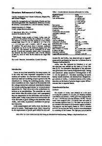
and 128 parameters. Except for fixing the H(1) position, no part of the refinement or structure was constrained. Table 3 lists the final atomic parameters for Keokuk kaolinite and Table 4 lists the atomic displacement parameters. D I F F U S E S C A T T E R I N G A N D A N A L Y S I S OF TWINNING Quite surprisingly for a crystal of as little as 8 Ixm3 volume, the intensity at beamline 11)13 was sufficient to record diffuse scattering. Note that the powder pattern of kaolinite from Keokuk shows little diffuse scattering. Diffraction patterns (Figure I) show very weak diffuse streaks parallel to [001]* through Bragg reflections, except for the 001 reflections, where the diffuse scattering is not observed. The intensity of the diffuse rods quickly decays with increasing distance from the Bragg reflection. Except for one weak spot along the streak from the 021 to the 022 reflection at 1 - 1.3 the decrease of the intensities is not modulated. No diffuse scattering is observed in the hk0 plane. This one-dimensional diffuse scattering is explained by stacking faults. The absence of observable diffuse scattering through the 00l reflections shows that the stacking consists of identical 7-/k layers and that the stacking faults consist of shifts of layers in the (001) plane. Different types of layers or a variation in dvalue between the layers is non-existent. The observed diffuse scattering was too weak to determine if reflections with k = 3n showed Jess diffuse scattering, as is commonly observed. A recent study of diffuse X-ray scattering by a kaolinite micro-crystal from Georgia (Grasl et aL, 1998) did reveal that the diffuse scattering through k = 3n reflections is weak compared to that through the other reflections. The intensity distribution o f the diffuse scattering suggests that the stacking faults are distributed at random intervals in the crystal. This observation shows that the Keokuk kaolinite, a kaolinite of exceptional quality as expressed by the Hinckley index of 1.90, is slightly disordered. Although this effect is small, it may have contributed to the difficulties encountered in the powder refinements of Suitch and Young (1983) and Young and Hewat (1988). The diffuse scattering observed in this experiment was too weak, however, to be analyzed in further detail. This diffuse scattering is, with one noteable exception, consistent with stacking faults of the kaolinite
Neder et al.
490
Clays and Clay Minerals
Table 4. Anisotropic displacement parameters. Atom
U~
U22
U33
U2~
Uj3
U~2
U,u~
All A12 Sil Si2 O1 02 03 04 05 OH1 OH2 OH3 OH4 H1 H2 H3 H4
0.0077(3) z 0.0078(3) 0.0068(2) 0.0062(2) 0.0072(6) 0.0097(6) 0.0142(7) 0.0074(6) 0.0081(6) 0,0092(7) 0.0116(7) 0.0112(7) 0.0108(7)
0,0088(7) 0.0088(7) 0.0078(6) 0.0075(6) 0.0117(15) 0.0101(15) 0.0093(15) 0.0132(16) 0.0124(15) 0,0122(16) 0.0097(16) 0.0131(16) 0.0151(18)
0.0074(3) 0.0082(4) 0.0066(3) 0.0072(3) 0.0065(6) 0.0070(7) 0.0104(7) 0.0112(7) 0,0086(7) 0.0124(8) 0.0095(7) 0.0094(7) 0.0094(7)
-0.0004(3) -0.0001(3) -0.0003(3) -0.0001(3) -0.0019(7) -0.0003(7) -0.0001(7) 0.0016(7) 0.0010(7) 0.0028(7) 0.0002(7) -0.0048(8) 0.0026(8)
0.0016(2) 0.0016(3) 0.0018(2) 0.0017(2) 0.0020(5) 0.0006(5) 0.0030(5) 0.0018(5) 0.0020(5) 0.0038(5) 0.0016(6) 0.0047(6) 0.0034(6)
0.0001(3) 0.0001(3) -0.0005(3) -0.0002(3) -0.0014(6) -0.0016(6) 0.0000(7) 0.0039(7) -0.0035(6) 0,0031(7) 0.0001(7) -0.0032(7) 0.0021(7)
0.0080(2) 0.0084(2) 0.0071(2) 0.0070(2) 0.0085(4) 0.0092(4) 0.0114(4) 0.0108(5) 0.0097(4) 0.0110(5) 0.0110(5) 0.0110(5) 0.0116(5) 0.194(58) 0.034(15) 0,082(28) 0.028(13)
For non-hydrogen atoms equivalent isotropic U, for hydrogen atoms isotropic U. 2 Values in parentheses are estimated standard deviations as given in the last decimal place.
Figure 1. Section of the diffraction pattern of the 8 /xm3 crystal, (a) The enlarged section shows the diffuse scattering parallel to [001]* through the 021 reflections. (b) The reflection at the bottom of this enlargement is the 021.
Vol. 47, No. 4, 1999
Crystal structure of kaolinite
Table 5. Si-O and AI-O bond lengths (A) for kaolinite. Bond
Distance (A)
Bond
Distance (A)
Si(1)-O(1) -0(3) -0(4) -0(5)
1.614(3)~ 1.620(3) 1.618(3) 1.628(3)
Si(2)-O(2) -0(3) -0(4) -0(5)
1.605(3) 1.622(3) 1.616(3) 1.615(3)
AI(1)-O(1) -0(2) -OH(l) -OH(2) -OH(3) -OH(4)
1.948(3) 2.001(3) 1.921(3) 1.853(3) 1.849(3) 1.862(3)
Al(2)-O(1) -0(2) -OH(l) -OH(2) -OH(3) -OH(4)
1.990(3) 1.946(3) 1.921(3) 1.867(3) 1.858(3) 1.853(3)
1Values in parentheses are estimated standard deviations as given in the last decimal place. structure as reported by Bookin et al. (1989), Plan~on e t al. (1989), and references therein. Bookin et al. (1989) analyzed the stacking models previously proposed in the literature. Based on arguments related to the lattice constants and the relative location of Si and A1 atoms in adjacent layers, the • the • 120 ~ and the vacancy displacement models were rejected. Two models were proposed, one with identical layers shifted by [0.017, 0.328, 0.0] and a second consisting of right- and left-handed kaolinite. They proposed that a mirror plane is normal to the (001) plane along the trace of the [110] direction, and calculated powder diffraction patterns are shown for the two models that are nearly similar. Accordingly, Bookin et al. (1989) concluded that an experimental distinction is problematic. This distinction is, however, possible in a single crystal experiment. A crystal containing only stacking faults between identical layers with a shift vector of [0.017, 0.328, 0.0[ will display a diffraction pattern with rods of diffuse scattering along the [001]* direction through all Bragg reflections, except the 00l reflections. If stacking faults occur at random intervals, the intensity will fade uniformly with increasing distance from the Bragg reflection. For a model with layers related by twinning, the diffraction pattern will differ. Kaolinite from Keokuk shows very weak diffuse scattering which means that the probability of stacking faults is low. A crystal with stacking faults involving layers related by twinning would consist of a few thick blocks of right- and left-handed kaolinite. Reciprocal space of such a crystal would consist of the overlay of the right- and left-handed reciprocal lattices. Due to the triclinic unit-cell shape, the Bragg reflections from the two twins will not coincide. The mirror plane suggested by Bookin e t al. (1989) will transform the Bragg reflections of left-handed kaolinite to non-integer positions in the reciprocal space of right-handed kaolinite and v i c e v e r s a . The 1i 0 Bragg reflection of left-handed kaolinite, for example, expressed in terms of the reciprocal lattice vectors of right-handed kaolinite is located at L1,0.6888, i.e., at non-integer l. The diffuse rods will be strongly modulated and the nature
491
of the modulation depends on the probability of stacking faults. The observed diffraction patterns do not show these modulations. Hence, the observed diffuse scattering of this crystal is not related to stacking faults from t w i n n i n g relationships but are due to shifted layers. Since the shape of the unit cell of kaolinite is triclinic, merohedral twins can not exist. The only twinning relationship where Bragg reflections will superpose is a twin involving a center of inversion. Since this implies stacking where adjacent 1:1 layers have opposing tetrahedral sheets or opposing octahedral sheets across the interlayer, this type of twinning is energetically very implausible. Since all observed Bragg reflections can be indexed with a single orientation matrix, the present crystal is untwinned. Twinning due to a mirror plane normal to the (001) plane along the trace of the [110] direction, however, was observed in the diffraction pattern of another single crystal of 0.4 ~xm3 volume by Neder et al. (1996b). RESULTS AND DISCUSSION The experimental observations are clearly consistent with space group C1. No reflections violating the space group were observed. The structure refines well in this space group and the non-hydrogen structure is very similar to the room-temperature X-ray powder diffraction study of Bish and VonDreele (1989) and the low-temperature neutron powder diffraction study of Bish (1993). Bish (1993) noted that the temperature decrease mostly affects the interlayer separation. The structure of the tetrahedral and octahedral sheets are nearly identical, although the octahedral thickness is slightly smaller at low temperature. The Si tetrahedra show a short Si-Oapicaldistance and larger Si-Obasoal distances (Table 5), with the Si-Oapi0al bond 0.013 A shorter than the average Si-Ob~a~bond. The corresponding bonds in the two tetrahedra are nearly identical. These results confirm the model of Hobbs et al. (1997), although the observed differences between the bond lengths are smaller than those reported by Hobbs et al. (1997). In contrast to the current results, the X-ray powder refinements of Bish and VonDreele (1989) yielded a longer Si-Oapical bond distance for the Si(2) tetrahedron, whereas the distances in the Si(1) tetrahedron showed no systematic relationship. The low-temperature neutron powder diffraction study of Bish (1993) showed no bond length differences in either tetrahedron. The AI-(O,OH) distances of this study are similar to those observed by Bish and VonDreele (1989) and Bish (1993) and calculated by Hobbs et al. (1997). The AI-Oapical bonds are significantly longer than the A1-OH bonds and the A1-OH(1) bond to the intralayer hydroxyl group is longer than the A1-OH bonds to the interlayer hydroxyl groups. The two A1 octahedra are nearly identical. The six A1-O bonds fall into two
492
Neder et al.
Table 6. Structural parameters for OH groups in kaolinite.
Atom
OH(l) OH(2) OH(3) OH(4)
O - H (A)
A n g le of O H with b axis I
0.75 36 ~ 0.76(6) 2 72(5) ~ 0.77(9) 64(5) ~ 0.88(7) 162(5) ~
Angle of O H with (001) plane
O-O Distance for H bond O - H .-. O(A)
12~ 64(4) ~ ..0(4) 3.088(3) 73(10) ~ ..0(4)2.989(3) 47(5) ~ ..0(4) 2.953(3)
Z(DHA)
Clays and Clay Minerals"
are acceptable values for X-ray data. The O - O distances for O - H . . O are 2.953(3), 2.989(3), and 3.088(3) A,, with bond angles of 142(5) ~ 173(9) ~ and 160(6) ~ at the vertex of the H atom. Position o f the intralayer hydrogen
160(6) ~ 173(9) ~ 142(5) ~
1 For easier comparison with Bish (1993) this angle is the angle between the b axis and the projection of the OH vector along the normal to the (001) plane onto the (001) plane. 2 Values in parentheses are estimated standard deviations as given in the last decimal place. 3 Bish (1993) lists the angle to the negative b axis.
groups with bond lengths of - 1 . 8 5 and 1.94 ,~, respectively. The o x y g e n atoms i n v o l v e d in the three longer bonds (two A1-Oapical bonds, A1-OH(1) bond) f o r m the o x y g e n atom plane that is c o m m o n to both the octahedral and tetrahedral sheets. The fact that the A1-Oapicaj bonds involve o x y g e n atoms that are shared by two A1 octahedra and the Si tetrahedra, whereas the A1-OH(1) bond i n v o l v e s an o x y g e n atom that is shared by two A1 octahedra only, appears to play only a m i n o r role. The b o n d lengths and b o n d angles within the two tetrahedra around Si(1) and Si(2) are v e r y similar to each other, as is the c o n n e c t i v i t y of these p o l y h e d r a to the adjacent Si tetrahedra and A1 octahedra. Consequently, the m e a n - s q u a r e d i s p l a c e m e n t s of the two Si atoms are similar. A l t h o u g h A1 octahedra display two groups of slightly different bond lengths, the respective bond lengths and bond angles within the two octahedra and their respective c o n n e c t i v i t y to adjacent octahedra are v e r y similar. Thus the atomic disp l a c e m e n t parameters o f Al(1) and Al(2) are also similar. Both Si atoms show almost isotropic disp l a c e m e n t parameters, because the Si o c c u p i e s the center of an almost regular tetrahedron. Apparently, the differences b e t w e e n the potentials of the Si-Oapical bonds and the Si-Obasa j bonds are too w e a k to i n d u c e anisotropic displacements. The A1 octahedra deviate slightly f r o m a regular p o l y h e d r o n and the six o x y g e n neighbors are i n v o l v e d in different topologies. Since the o b s e r v e d d e v i a t i o n f r o m isotropic d i s p l a c e m e n t s is small, the shape o f the potential field distribution at the A1 site must be nearly that o f a regular octahedron. The o x y g e n atoms show m o r e p r o n o u n c e d anisotropic d i s p l a c e m e n t vectors since they are inv o l v e d in m o r e irregular coordination and the potential along the S i - O b o n d is e x p e c t e d to be v e r y different f r o m the potential in a plane n o r m a l to this bond. The interlayer O - H vectors associated with the H bonding are nearly normal to the (001) plane (Table 6). The O - H bond distances are 0.76-0.88 A, which
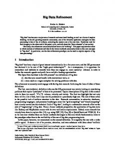
As noted above, the position of the intralayer hydrogen could not be refined, although its location was determined by difference-Fourier methods. T w o cross sections through the difference map (Figure 2) show one m a x i m u m at 0.142, 0.035, 0.347. N o e v i d e n c e exists for a second m a x i m u m either above or b e l o w the z = 0.347 plane, as w o u l d be expected if the space group P1 (Young and Hewat, 1988) is correct. Besides the systematic absences o f h + k ~ 2n, this is further e v i d e n c e for space group C1. The d i s p l a c e m e n t p a r a m e t e r o f H(1) is large for n o r m a l thermal vibrations. C o n s i d e r i n g the constraints applied during the refinement, the m a g n i t u d e of the d i s p l a c e m e n t p a r a m e t e r must be interpreted with caution. H o w e v e r , the distribution of e l e c t r o n density in the d i f f e r e n c e - F o u r i e r m a p s is consistent with the large v a l u e o f the d i s p l a c e m e n t parameter. T h e s e d i f f e r e n c e - F o u r i e r m a p s (Figure 2) s h o w electron density near the H(1) position [as calculated f r o m a m o d e l without H(1)]. T h e density distribution is clearly anisotropic and a p p r o x i m a t e l y arc shaped, w h i c h suggests a thermal libration o f the H(1) position around the c o r r e s p o n d i n g O H ( l ) position at a nearly constant b o n d distance. The c o r r e s p o n d i n g diff e r e n c e - F o u r i e r m a p s of the interlayer H atoms do not show such d e l o c a l i z e d and anisotropic electron densities. S u c h a density distribution cannot be d e s c r i b e d by an isotropic atomic d i s p l a c e m e n t parameter. C o n trary to the l o w - t e m p e r a t u r e neutron p o w d e r diffraction study (Bish, 1993), the shape o f the d i f f e r e n c e F o u r i e r peak shows its greatest e l o n g a t i o n in the (001) plane. T h e current results, however, w e r e obtained f r o m single-crystal X - r a y data c o l l e c t e d at r o o m temperature, w h i c h are less reliable for determ i n i n g the location of h y d r o g e n atoms than neutron experiments. A m o r e d e t a i l e d analysis o f a n i s o t r o p i c d i s p l a c e m e n t p a r a m e t e r s for H(1) is not p o s s i b l e b e c a u s e the scattering a m p l i t u d e o f h y d r o g e n is too small. T h e h i g h v a l u e of U ( H 1 ) p r o b a b l y results f r o m b o t h thermal v i b r a t i o n and r a n d o m static d i s p l a c e m e n t . T h e s e o b s e r v a t i o n s are in a g r e e m e n t w i t h t h o s e o f B i s h (1993). T h e a n g l e b e t w e e n the O - H ( 1 ) b o n d and the (001) p l a n e is 12 ~ (Table 6) and, b a s e d on the diff e r e n c e map, the e s t i m a t e d standard d e v i a t i o n is n e a r 5 ~. Thus, the o b s e r v e d a n g l e o f 12(5) ~ is h i g h e r than the a n g l e (0.34 ~ o b s e r v e d by B i s h (1993) or that c a l c u l a t e d (3.8 ~ by H o b b s et al. (1997) and r e p o r t e d (3.8 ~ by H e s s and S a u n d e r s (1992). H o w ever, large t e m p e r a t u r e d i f f e r e n c e s b e t w e e n the exp e r i m e n t a l c o n d i t i o n s m a k e s c o m p a r i s o n difficult.
Vol. 47, No. 4, 1999
Crystal structure of kaolinite
493
at 0.347 1.1
1.05
1
0.95
0.9
0.85 -0.2
-0.1
0.1
0.2
0.3
[1oo1
-0.1
-0.05
0
0.05
0.1
0.15
0.2
[1 10]
Figure 2. Difference-Fourier map of the final model without H(1) included in the model. The contour lines are in intervals of 0.1 electrons/A3, starting at 0.1 and - 0 . 1 , respectively, a) Difference-Fourier map in the (001) plane at the z of the maximum difference-Fourier at z ~ 0.347. The (• in the center of the plot corresponds to the final refined x,y position of the OH(l), which is at z = 0.325, and the (+) corresponds to the x,y position of H(1). b) Difference-Fourier map in the plane defined by the OH-vector and the c axis. This plane is at an angle of 7 ~ to the (110) plane. The (• in the center of the plot corresponds to the final refined x,z position of OH(l), and the (+) corresponds to the x,z position of H(1). A l s o , e n e r g y - m i n i m i z a t i o n c a l c u l a t i o n s are s t r i c t l y v a l i d at T = 0 K. A s e x p e c t e d f r o m a r e f i n e m e n t b a s e d on X - r a y data, the positional p a r a m e t e r s o f the H a t o m s are o f l o w e r p r e c i s i o n than the n o n - h y d r o g e n atoms. H o w e v e r , for a crystal o f v o l u m e o f only 8 }xm3, the r e f i n e m e n t o f the H p o s i t i o n s and their isotropic d i s p l a c e m e n t par a m e t e r s are quite remarkable. Such results w e r e obtained b e c a u s e o f the high s i g n a l - t o - n o i s e ratio and the n u m e r o u s h i g h - a n g l e reflections (20mo~ = 76 ~ processed. ACKNOWLEDGMENTS We are indebted to W. Keller, University of Missouri, who kindly supplied the kaolinite samples from Keokuk, Iowa. We appreciate the support by H. Koop, Institute for Botany, University Mtinchen, who showed us how to make the micrometer-sized glass fibers. The samples were mounted, using the SEM at the Department of Geosciences, University of Mtinchen. A travel grant and beam time at the ESRF is gratefully acknowledged. This work was supported by the BMBF under grant 05 647 WMA5. We are especially thankful for the constructive criticism of the reviewers. REFERENCES Adams, J.M. (1983) Hydrogen atom positions in kaolinite by neutron profile refinement. Clays and Clay Minerals, 317 352-356. Bish, D.L. (1993) Rietveld refinement of the kaolinite structure at 1.5 K. Clays and Clay Minerals, 41, 738744. Bish, D.L. and Von Dreele, R.B. (1989) Rietveld refinement of non-hydrogen atom positions in kaolinite. Clays and Clay Minerals, 37, 289-296.
Bookin, A.S., Drits, V.A., Planqon, A., and Tschoubar, C. (1989) Stacking faults in kaolinite-group minerals in the light of real structural features. Clays and Clay Minerals, 37, 297-307. Grasl, T., Neder, R.B., Schulz, H., and Burghammer, M. (1998) Einkristallbeugungsexperimente an einem stark fehlgeordneten Kaolinit. Zeitschrift .far Kristallographie, Supplement, 15, 136. Hess, A.C. and Saunders, V.R. (1992) Periodic ab initio Hartree-Fock calculations of the low-symmetry mineral Kaolinite. The Journal of Physical Chemistry, 96, 43674374. Hobbs, J.D., Cygan, R.T., Nagy, K.L., Schultz, RA., and Sears, M.P. (1997) All-atom ab initio energy minimization of the kaolinite crystal structure. American Mineralogist, 82, 657-662. Koch, A. (1994) Lens coupled scintillating screen-CCD Xray area detector with a high detective quantum efficiency.
Nuclear Instruments and Methods in Physics Research A,
348, 654-658. Neder, R.B., Burghammer, M., Grasl, T., and Schulz H. (1996a) Mounting an individual submicrometer sized crystal. Zeitsehriftfiir Kristallographie, 211, 365-367. Neder, R.B., Burghammer, M., Grasl, T., Schulz, H., Bram, A., Fiedler, S., and Riekel, Ch. (1996b) Single crystal diffraction by submicrometer sized kaolinite; observation of Bragg reflections and diffuse scattering. Zeitschrift fiir Kristallographie, 211, 763-765. Planqon, A., Giese, R.F., Snyder, R., Drits, V.A., and Bookin, A.S. (1989) Stacking faults in the kaolinite-group minerals: Defect structures of kaolinite. Clays and Clay Minerals, 37, 203-210. Smr~ok, L., Gyepesovfi, D., and Chmielovfi, M. (1990) New X-ray Rietveld refinement of kaolinite from Keokuk, Iowa. Crystal Research and Technology, 25, 105-110. Suitch, ER. and Young, R.A. (1983) Atom positions in highly ordered kaolinite. Clays and Clay Minerals, 31, 357 366.
494
Neder et al.
Thompson, J.G. and Withers, R.L. (1987) A transmission electron microscopy contribution to the structure of kaolinite. Clays and Clay Minerals, 35, 237-239. Thompson, J.G., Fitz Gerald, J.D., and Withers, R.L. (1989) Electron diffraction evidence for C-centering of non-hydrogen atoms in kaolinite. Clays and Clay Minerals, 37, 563565.
Clays and Clay Minerals
Young, R.A. and Hewat, A.W. (1988) Verification of the triclinic crystal structure of kaolinite. Clays and Clay Minerals, 36, 225-232.
(Received 2 April 1998; accepted 17 February 1999; Ms. 98-043)