to the branch metrics from each bit-row in a stripe and 2) inclusion of an ... Color versions of one or more of the figures in this paper are available online .... in the MVA, we consider a table that maps a 7-bit cluster ..... edu/~weeksw/pub.html.
IEEE TRANSACTIONS ON MAGNETICS, VOL. 43, NO. 7, JULY 2007
3333
Refinements of Multi-Track Viterbi Bit-Detection Andries P. Hekstra, Wim M. J. Coene, and Andre H. J. Immink Philips Research Laboratories, 5656 AE Eindhoven, The Netherlands In optical storage, data can be arranged on the disc in a meta-spiral consisting of a large number of bit-rows with a small track-pitch. Successive revolutions of the meta-spiral are separated by a narrow guard band. For high storage densities, such a system results in severe 2-D inter-symbol interference. In the multi-track Viterbi algorithm (MVA) of Krishnamoorthi and Weeks, the complex problem of 2-D bit-detection is broken down into a number of smaller bit-detection problems on sets of adjacent bit-rows called stripes. We improve the bit error rate (bER) performance of such a 2-D bit-detector via a number of measures such as: 1) weighing of the separate contributions to the branch metrics from each bit-row in a stripe and 2) inclusion of an additional contribution to the branch metrics from a bit-row adjacent to a stripe. In addition, we reduce the computational complexity by varying the number of bit-rows per stripe during successive iterations of the MVA, and through the use of local sequence feedback. Index Terms—Optical recording, 2-D inter-symbol interference, 2-D Viterbi detection.
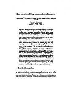
I. INTRODUCTION N two-dimensional (2-D) storage on an optical disc, data are recorded in a meta-spiral comprising a limited number of consecutive bit-rows (e.g., ten). The bit-rows in the meta-spiral are recorded with a fixed phase-relation between each other, and with a very small track-pitch. Successive revolutions of the meta-spiral are separated by a narrow guard-band with a maximum width of one bit-row. This 2-D format is shown in Fig. 1. Such a 2-D format is ideally suited for a parallel read-out with a one-dimensional array of laser spots, which after being diffracted at the data structures on the disc, are detected by a one-dimensional array of photo-detectors. The resulting 1-D array of signal waveforms is sampled in time, and yields at the input of the receiver a 2-D array of waveform samples. In the meta-spiral, the channel bits are arranged on a 2-D lattice. One possible choice is to use a 2-D close-packed hexagonal lattice since it has a 15% higher packing fraction than the square lattice as proposed in [1] and [2]. In a linear approximation, the modulation transfer function (MTF) of the channel for optical read-out has the characteristics of a 2-D low-pass filter, whose shape can be approximated by a 2-D cone as outlined in [3] and [4]. The radius of the cone beyond which no inforcorresponds to the cutoff frequency mation is transferred by the channel. Compared to the conventional 1-D formats in optical recording (such as CD, DVD, and Blu-ray Disc, BD), the track pitch in the 2-D format is considerably reduced, by a factor that can be even larger than two: in the resulting 2-D inter-symbol interference (ISI), the inter-track interference may even become as significant as the “along-track” 1-D ISI, as is the case when a 2-D hexagonal bit-lattice is used. The interest of the scientific storage community in signal processing for two-dimensional storage channels is obvious from recent papers like [5] and [6], the latter paper even dealing with multi-level instead of binary two-dimensional storage.
I
Digital Object Identifier 10.1109/TMAG.2007.897665 Color versions of one or more of the figures in this paper are available online at http://ieeexplore.ieee.org.
Fig. 1. Schematic two-dimensional format for storage on an optical disc (for simplicity a seven-row meta-spiral is shown).
Fig. 2. Simplified linearized 2-D impulse response for 2-D optical storage.
A. Joint 2-D Bit-Detection In this paragraph, we evaluate the significance of the intertrack ISI relative to the “along-track” ISI in case of the hexagonal bit-lattice. Fig. 2 shows a reasonable approximation of the channel by a 2-D impulse response with a central tap , and with six nearest-neighbor taps (we will refer further to these six nearest-neighbors as the first shell of neighboring bits). This situation applies for a disc capacity of two times that of Blu-ray Disc (BD), the third generation of optical storage (see, e.g., [7], [8]). BD has a capacity of 25 GB and is based on the conventional 1-D format with a spiral consisting of a single bit-row. The total energy of this 2-D impulse response equals 10, with an energy of 6 along the axis of the meta-spiral, and an energy of 2 along each of the neighboring bit-rows. From these energy considerations, one of the main advantages of a 2-D format is
0018-9464/$25.00 © 2007 IEEE
3334
obviously “joint 2-D bit-detection,” which means that all signal energy associated with a single bit is used for bit-detection. This contrasts with 1-D bit-detection in the conventional 1-D format where inter-track interference is tackled via cross-talk cancellation [9] (similar to the well known technique of echo-cancellation). In the latter case, still assuming the hexagonal 2-D format at two times BD capacity, only the energy “along-the-bit-row” is being used, thus yielding a 40% loss of energy-per-bit. The motivation behind 2-D (optical) storage is that: • much less disc space is wasted as guard space; • full 2-D bit-detection can take advantage of cross-talk signal components as signal energy that contributes to the 2-D bit-detection; by doing so the storage capacity of the disc can be increased, e.g., doubled w.r.t. BD, while using the same “physics” in the read-out; • at a given rotational speed of the disc, the data rate during read-out is multiplied with the number of laser spots. B. Full-Fledged 2-D Viterbi Bit-Detection The bit-rows of a meta-spiral are aligned along the axis of the meta-spiral, which we refer to as the tangential direction. Also in directions under 60 (and 120 ) with the tangential direction, the bits are aligned along so-called bit-columns. For a channel with 2-D ISI, a full-fledged Viterbibit-detector would comprise all bit-rows of the meta-spiral. One of the difficulties of designing such a bit-detector is that the finite-state machine representing the 2-D channel would require“states” that consist of one or more columns of bits. For instance, if the tangential span of the channel model consists of taps, and if the meta-spiral consists of bit-rows, then the number of states becomes . Each of these states has also predecessor states, thus in total the number of branches equals . As an example, for the one-shell model which we consider below (one central and six “nearest neighbor” taps), we have . Thus, for a meta-spiral with bit-rows, a full-fledged 2-D Viterbi bit-detector is totally impractical from a hardware point of view. C. Literature on Multi-Track Viterbi Algorithm The basic principles underlying the 2-D bit-detection scheme reported in this paper have already been described in the M.S. thesis of Krishnamoorthi [10] and in the Ph.D. thesis of Weeks [11], where it is referred to as the multi-track Viterbi algorithm (MVA). 2-D storage is studied mainly in the area of optical storage; see the competing work in [2], [12], [13], albeit on square instead of hexagonal 2-D bit-lattices. Note that our approach applies to any type of 2-D bit-lattice. Another important difference is that the 2-D bit-detector of [2] uses a set of independent Viterbi machines that process three consecutive bit-rows and output the bits of the center bit-row. The stripe-wise approach of the MVA-algorithm on the other hand is based on a concatenation scheme of interconnected Viterbi machines in which the output of outer bit-rows for previous stripes is passed as side-information for subsequent stripes. Similarly, magnetic storage can also be adapted towards a 2-D format, and some papers start to appear in the literature [14]. The scheme of [15] has similarities with the MVA scheme, but departs from principles of Turbo coding. It passes on soft-decision information in between successive iterations
IEEE TRANSACTIONS ON MAGNETICS, VOL. 43, NO. 7, JULY 2007
and stripes. However, in our experience, passing soft-decision information within the stripe-wise scheme does not yield an improvement in bit-detection performance over passing hard-decision information. D. Results of This Paper and Structure of the Paper With respect to the MVA algorithm of [10], [11], we introduce a number of additional measures that significantly improve the bit-detection performance: i) weighing of the separate contributions to the branch metrics from each bit-row in a stripe, with a weight-factor that is dependent on the row-number within a stripe and on the iteration-number in the MVA; ii) inclusion of an additional contribution to the branch metrics from a bit-row adjacent to a stripe; and iii) processing the consecutive stripes starting from both guard bands towards the center. In addition, unlike the MVA which uses straightforward decision feedback from one stripe to the next, our approach uses the output of a previously processed stripe to condition the reference levels in the branch metrics for the next stripe. In this way, nonlinear ISI can be handled as well. Note that for the 2-D optical storage channel that we consider in this paper, the nonlinear ISI resulting from a bit-row just above a current stripe depends on the actual branch in the Viterbi-trellis of the stripe. Finally, we reduce the computational complexity by varying the number of bit-rows per stripe during successive MVA iterations, and through the use of local sequence feedback. The paper is structured as follows. In Section II, we briefly describe the MVA algorithm together with some practical notations. Next, Sections III and IV discuss the performance improvements and complexity reductions of our “preferred schemes.” Finally, in Section V we present simulation results, and in Section VI we formulate our conclusions. II. MVA ALGORITHM A. The Concept of Stripes The 2-D hexagonal lattice has two axes, denoted and , with Cartesian coordinates defined with respect to the tangential and radial direction of the meta-spiral, given by
(1) A 2-D block of channel bits is denoted . A set of points refers to a bit-row with index (where “ ” with indices bit-rows, with denotes a “wildcard”). The meta-spiral has an empty bit-row as a guard band on its top and bottom side. A stripe is defined as a number of adjacent bit-rows. For each stripe, we have a Viterbi processor (which we call per-stripe processor). One iteration of the stripe-wise scheme will have as output bit-decisions for all bit-rows of the meta-spiral. We assume further that, for a given iteration of the stripe-wise scheme, all stripes have the same number of bit-rows. Note that all per-stripe processors, except the last one, have as output only a single bit-row, which can be the top or bottom bit-row of the stripe (see Section II-E); the last stripe-processor will have as output all of its bit-rows. Then, the total number of stripes is . given by
HEKSTRA et al.: REFINEMENTS OF MULTI-TRACK VITERBI BIT-DETECTION
3335
C. The Stripe-Wise Solution of MVA The basic principle of the stripe-wise scheme is that a set of per-stripe processors is executed in one iteration, where each (except the last) per-stripe processor yields one of its outer bit-rows as output, which is passed on to the subsequent perstripe processor as side information (at that side of the subsequent stripe that is closest to the current stripe); also, bit-decisions from one iteration can be passed on to the next iteration of the stripe-wise scheme where it is used as side information for the other side of the stripes so that all branch metrics can be unambiguously evaluated. We consider a stripe : at time index , its per-stripe bitdetector is working on the trellis stage of bit-column
Fig. 3. Signal patterns for 2-D hexagonal bit-lattice (drawn as a function of the cluster type) for BD read-out parameters with lattice parameter a = 138 nm.
B. One-Shell Channel Model In optical recording, the signal waveform as measured during read-out of an optical disc can be accurately modeled through a signal processing model [16] based on scalar diffraction theory [4]. An example for a 2-D bit-lattice with a lattice parameter nm is shown in Fig. 3: this corresponds with a capacity of twice that of the BD format (using the same physical parameters for read-out). A “1”-bit corresponds to a hexagonal bit-cell with a circular pit-mark at its center. A “0”-bit does not have such a pit-mark. The signals can be interpreted in terms of the 14 possible 7-bit hexagonal bit-clusters (assuming a 2-D isotropic channel). A cluster consists of a central bit and its six nearest neighbor bits. The curve at the left-hand side in Fig. 3 represents the values of the ideal signal waveform with a “0”-bit in the center of the cluster, for increasing number of neighboring “1”-bits (from 0 to 6); the curve at the right-hand side in Fig. 3 represents the values of the ideal signal waveform with a “1”-bit in the center of the cluster, also for an increasing number of neighboring “1”-bits. Note also the nonlinearity especially at the right-hand side curve. Numerical investigations have shown that for storage densities two times higher than that of BD, the accuracy of the one-shell model as defined above is adequate for reliable bit-detection. Thus, we set , the number of taps along the tangential . direction of the meta-spiral, equal to For the computation of the reference signal levels to be used in the MVA, we consider a table that maps a 7-bit cluster onto expected values of the (equalized) signal waveform. Table has entries. An equalizer filter can be used to enforce a certain symmetry so that the size of the table can be reduced. Due to the intrinsic nonlinearity of the channel response, such nonlinear equalizer filters may become quite complex [17]. The stripe-wise bit-detection scheme does not need such nonlinear equalizer filters since it can deal with tables of arbitrary responses . Those arbitrary responses may account for the nonlinearities of both the write-channel and the read-channel.
where the sequence represents the delays of the various per-stripe machines with respect to the first one. taps, The 2-D target response has a tangential extent of . In the per-stripe Viterbi bit-detector, for stripe e.g., the index set of the departure state consists of
(2) whereas an arrival state index set is shifted forward one position .A in the (tangential) -direction, that is, departure state is an assignment of bit values on the index set , and an arrival state is an assignment of bit values on . There are possible arrival states the index set (and the same number of departure states). A departure state and an arrival state are connected in the trellis if their bit . Obvivalues agree in the common positions out of the set of branches ously, this constitutes the branch denoted . A Viterbi bit-detector that operates on a stripe of only two or three rows still has a reasonable complexity, contrary to the , the number of impractical full-fledged detector. With states equals 16 for a two-row stripe, and 64 for a three-row stripe. The number of outgoing branches per state amounts to 4 and 8, respectively.
D. Computation of the Branch Metrics and Viterbi Recursion In the trellis of a stripe , a branch specifies bit . The reference signal values for all points in waveform samples are computed at the positions in bit-column (assuming the one-shell model with ). For each of these bit-positions, we need the bit-values of the bits at the nearest-neighboring bit-positions. To this end, we also need certain bits from the array of current estimates in the bit-row above and the bit-row below the considered stripe so that we can evaluate the entries for the tables . We denote this mapping
3336
IEEE TRANSACTIONS ON MAGNETICS, VOL. 43, NO. 7, JULY 2007
Fig. 4. Top-to-bottom stripe-wise processing (as in original MVA algorithm) for an 11-row meta-spiral using two-row stripes. Note that a bit-row is represented by a grey area bounded by two solid lines on either side.
of the meta-spiral. The delay of “V01” with respect to “V00” matches the trace-back depth of the Viterbi processor for “V00.” Thus, the output row of the first stripe “V00” serves as high certainty border row of the second stripe “V01” and can be used in the computation of the branch metrics of that stripe. This procedure is continued for all stripes: the full procedure from top to bottom of the meta-spiral constitutes one iteration of the stripe-wise scheme. F. Small Number of Iterations
. The metric for a branch with HF denoting the (equalized) signal waveform
becomes,
(3) As is well-known in detection theory, the squaring of the terms goes back to the assumption of additive (white) Gaussian noise. Based on these branch metrics, the add-compare-select (ACS) operation of the Viterbi algorithm performs a recursive update of the path metrics (denoted )
E. Sequence of Stripes in Original MVA Algorithm Fig. 4 shows an 11-row meta-spiral with two-row stripes. corresponds to the top row in the figure. Row index value A uni-directional sequence of Viterbi stripe-processors, named “V00,” “V01,” , “V09” is suggested. All Viterbi stripe-processors, except “V09,” produce as output their top bit-row; the last stripe-processor “V09” outputs both its bit-rows. The use of the one-shell channel model implies that the signal waveform for a bit-position within a given stripe depends on all its nearest neighbor bits, some of which lie within this stripe but others lie either within the bit-row immediately above the stripe or within the bit-row immediately below the stripe. These bits outside the stripe can be considered as side-information that is required for the Viterbi bit-detector of this stripe. For the stripe that corresponds to “V00,” the aforementioned border row im. This mediately above the stripe is the guard band bit-row is known—i.e., is of “high certainty”—as it is modeled as containing all zero bits. For “V00,” the difficulty lies in the aforementioned border row immediately below the stripe. This row contains unknown data—i.e., is of “low certainty”—as it contains bits that are yet to be detected, or that have been detected during a previous iteration of the stripe-wise scheme. Note that the observation that a stripe has a “high certainty” and a “low certainty” border row is true for all stripes in the stripe-wise scheme (except the last stripe). For each stripe, the bit-row detected with the highest reliability is considered to be the output of that stripe, and is stored either for further use by Viterbi bit-detectors of subsequent stripes, or for further iterations, or for the final output. The second stripe in Fig. 4, denoted “V01,” contains the second and third bit-rows
In the previous paragraph, we have explained how the output bit-row of a stripe can be used as side information at the high certainty side of the subsequent stripe. In a similar fashion, the output bit-rows of a given iteration can be used as side information at the low certainty side of all stripes of the next iteration. That is, for the low-certainty border rows, during all subsequent iterations, it is no longer necessary to use arbitrary guesses or threshold decisions as is the case in the first iteration. Therefore, we can expect that the bit error rate (bER) after the second iteration has decreased compared to that of the first iteration. Possibly a third iteration can be implemented, etc. Beyond a certain iteration, the bER will not decrease significantly anymore. At that point, the bER is limited by error-events that typically extend in the radial direction well beyond the width of a stripe. This phenomenon reflects the error floor of the stripe-wise scheme. Note that the severity of a real error floor depends on the channel response, and may not be a problem at the currently envisaged densities. III. PERFORMANCE IMPROVEMENTS OF THE PER STRIPE BIT-DETECTORS A. Certainty Propagates From the Guard Bands The empty guard band can be modeled as if it contains virtual bits, all equal to zero. Bit error rate analysis of the per-stripe bit-detectors of Fig. 4 reveals that the bER increases for bit-rows with increasing distance from the top guard band. The guard bands with their 100% reliability constitute the anchor points for the stripe-wise bit-detection scheme. In order to achieve a bER performance that is roughly the same for the top half and the bottom half of the meta-spiral, the per-stripe bit-detectors are consecutively executed on alternating sides of the meta-spiral. In this way, the knowledge of the bits in both guard bands is exploited in a symmetric fashion. This can be seen as a bi-directional strategy for successive per-stripe bit-detectors. Note that this is a different strategy as compared to [11], where stripes are processed in a uni-directional way, that is, from top to bottom of the meta-spiral. In the bi-directional case, successive stripes are arranged in a “ ”-shape as can be seen in Fig. 5 with stripes consisting of two bit-rows as applies in the first iteration. The even-indexed per-stripe Viterbi bit-detectors “V00,” “V02,” , “V08” have their top bit-row as output row. In analogy, the odd-indexed per-stripe Viterbi bit-detectors “V01,” “V03,” , “V07” have as output row their bottom bit-row. Finally, the two cascades of stripes are terminated in the middle of the meta-spiral with a last stripe “V09,” which outputs its two bit-rows. Obviously, a similar reasoning applies
HEKSTRA et al.: REFINEMENTS OF MULTI-TRACK VITERBI BIT-DETECTION
Fig. 5. Bi-directional “outwards-to-inwards” order of stripe-wise processing. Two iterations of stripe-wise processing are shown. Each iteration is performed by a “ ”-shape of per-stripe bit-detectors that proceed from the guard band to the center of the meta-spiral. In this example, the second iteration—which corresponds to the left “ ”-shape—uses stripes with 3 bit-rows per stripe, one more than the 2 bit-rows per stripe of the first iteration.