locations and subsequent data processing operations is described. Reflection ..... era viewing axis, such as a ring flash, also produces shadow- less images .... the coin and card from the surrounding template to mute ..... ture Shape Recovery.
The 6th International Symposium on Virtual Reality, Archaeology and Cultural Heritage VAST (2005) M. Mudge, N.Ryan, R. Scopigno (editors)
Reflection Transformation Imaging and Virtual Representations of Coins from the Hospice of the Grand St. Bernard †
*
†
†
Mark Mudge , Jean-Pierre Voutaz , Carla Schroer , and Marlin Lum † Cultural Heritage Imaging, San Francisco, California, USA * Congregation of the Grand St. Bernard, Switzerland
Abstract Reflection transformation imaging offers a powerful new method of documenting and communicating numismatic cultural heritage information. The challenges of documenting numismatic material will be examined along with the limitations of traditional documentary techniques. Previous uses of structured light scanning and PTMs in numismatic documentation are reviewed and evaluated. A novel, low cost method for capturing PTMs at remote locations and subsequent data processing operations is described. Reflection transformation imaging is shown to capture more complete documentation than traditional photographic methods and communicate this information with ease through digital media. The advantages of interactive relighting of numismatic PTM images in conjunction with enhancement operations are explored along with the potential of informed choice of the most information rich illumination directions. Advantages of joint capture of structured light and PTMs are examined including the inherent registration of range and normal data, using range and normal information together to improve 3D position accuracy, and the enhanced evidentiary reliability that results. 1. Introduction Since the advent of coinage in western Asia Minor during the late 8th century and early 7th century BCE, numismatic material has played a central role in the story of humanity’s past. Coins, and their distribution patterns, reflect the political and economic activity of the societies in which they were used. As small bas-relief sculptures, coins form a record of artistic styles and iconography. Though small, many are considered among the finest expressions of our ancestor’s sculptural work. We will examine how virtual reality representations employing reflection transformation imaging capture a robust information set which can be illuminated from any direction, permitting the interactive and intuitive examination of coins. We will see how specular reflections from materials like gold are handled robustly and without data loss. Examples will demonstrate that mathematical enhancement of reflectance information can disclose as much, if not more, data than direct physical inspection. 2. Background of Reflection Transformation Imaging and previous applications. The term ‘Reflection Transformation’ was first used by Tom Malzbender of Hewlett-Packard (HP) Labs in connec-
tion with a set of image processing methods he invented known as Polynomial Texture Mapping (PTM) [MWG2001]. Malzbender et al. presented a mathematical model describing luminance information for each pixel in an image in terms of a function representing the direction of incident illumination. The illumination direction function is approximated in the form of a biquadratic polynomial whose six coefficients are stored along with the color information of each pixel. The per pixel information is able to record properties including surface inter-reflection, subsurface scattering, and self-shadowing. The per pixel information present in the polynomial coefficients is important in cultural heritage applications because it contains essential shape data about the subject of the 2D PTM image. By determining the brightest direction dependant luminance value for each pixel, the polynomial function indicates the directional vector, relative to the XY plane of the image, corresponding to the source position of the incident illumination that produced it. In turn, this directional vector discloses key information about the shape of the original object at the spatial location represented in the PTM image by that pixel. The directional vector pointing toward the source of the brightest incident illumination for that pixel is identical to what is mathematically known as the ‘normal’ vector perpendicular to the surface of the represented object at the position indicated by the pixel. Taken
Mudge, Voutaz, Schroer, Lum / Reflection Transformation Imaging and Virtual Representations of Coins from the GSB collectively, the normals of a surface describe its shape and are used by computer graphics lighting models to determine surface reflection properties [P1975]. Consequently, PTMs can be understood as 2D images possessing true three dimensional data. This three dimensional data is retrieved from the PTM through interactive viewing software employing various methods of reflection transformation imaging. PTMs differ from previous work in the shape from shading category including photometric stereo [KSK1988] and more recent Bidirectional Texture Function (BTF) and normal aquisition approaches employing concave parabolic mirrors [WD2003]. Beyond the use of a polynomial representation, PTMs can communicate useful shape information using purely image based transformations with new material properties in light space without full photometric stereo or other reconstruction from the surface normals in 3D Cartesian space. When used in Cartesian space, these normal based reconstruction methods are known to generate low frequency ‘warps’ in their resultant 3D geometry. This is also true for integration of geometry from PTMs. Because of this limitation, surface orientation information has often been used as bump maps in the rendering of 3D geometry rather than as a source of original geometry [BMMR2002]. While PTMs have also been used to add surface orientation information to acquired geometry as will be seen in section 2.2, when used independently from 3D geometry, light space based reflectance transformation imaging will be seen to communicate large amounts of empirically useful shape information. Light space is a mathematical construct built with a three dimensional parametric geometry representing the information describing the impact of incident illumination direction upon the luminance intensity of the PTM image’s pixels. When interactively examining a PTM image, light space can be thought of as a hemispheric dome enclosing the PTM. This imaginary dome corresponds to the parametric geometry of the light space mathematically stored in the form of polynomial coefficients in the PTM image’s pixels. Because PTMs use essentially the same 3D lighting models used to render 3D geometry, image content can be interactively illuminated by the user as if it occupied 3D Cartesian Space. In PTM viewing software, when the user drags their mouse through the 2D region representing the image’s light space, they are dragging their mouse over a hemispheric volume. When the mouse cursor is in the center of the light space area, the illumination is analogous to the sun at 'high noon'. As the mouse cursor is dragged toward the edge of the light space area, the sun approaches the 'horizon'. Illumination in Light Space has similarities with illumination in the 'real world'. The PTM Viewer's viewing location is fixed perpendicular to the image plane, at the Light Space dome's 'high noon'. Illumination originating from the same 'high noon' location, equivalent to the center of the PTM,
will be mainly reflected back to the viewing location and will be at its brightest. As the light direction approaches the horizon, equivalent to the edge of the PTM, fewer light rays will find their way to the viewing location and the PTM will be less brightly illuminated.
Figure 1: Silver Athenian Tetradrachma, 449 BCE Figure 1 shows three images from the same PTM with the light source coming from three different directions. In the left image, the light is positioned at 'high noon'. In the middle image, the light is positioned near the 'horizon' from the direction corresponding to the top of the image. In the right image, the light is positioned near the 'horizon' from the direction corresponding to the bottom of the image There are two implementations of PTM viewing software. The first PTM Viewer software, written in C++, was developed at HP Labs [HPLweb]. The second, written in Java, was developed by Harvard graduate student Clifford Lyon [Lyonweb]. While each viewer possesses unique attributes, they share a core functionality and user experience of light space. It is through this transforming interplay of light and shadow over the surface of the represented object that PTMs communicate the nature of the object’s form. The intuitive similarity of the interplay of light and shadow over shapes in the ‘real world’ in our everyday experience to the experience offered by reflection transformation imaging is the source of this technique’s documentary and communicative power. As we have seen, existing PTM viewers enable illumination of a subject from all directions possible in the ‘real’ world. PTMs also enable reflection transformation models that mathematically enhance 3D shape information. The two enhancement methods present in PTM viewing software are ‘Diffuse Gain’ and ‘Specular Enhancement’. The work by researchers in a number of fields reviewed in section 2.1 will demonstrates the value of these techniques and that the diffuse gain and specular enhancement modalities of PTMs permit extraction of empirical data not discernible to the naked eye, standard magnification methods, or traditional photographic techniques. PTMs of physical objects also possess properties which can algorithmically indicate how to light an object in a manner that will capture the most information about it. The determination of the most informative illumination direction
Mudge, Voutaz, Schroer, Lum / Reflection Transformation Imaging and Virtual Representations of Coins from the GSB of an object from a given viewpoint can be made through a maximum entropy analysis [MO2005]. Given the ability to relight a properly captured PTM from any arbitrary direction, the lighting direction that conveys the most information about the object can be analytically derived. In principle, it is possible to determine and generate the most informationally rich view of an object at a time subsequent to the empirical documentation of the object. This process can also be used to determine the most informative illumination direction when using enhancement methods. These enhancement methods can be pragmatically applied to the PTM and the informationally optimum lighting direction computed according to the requirements of the user. 2.1 2D virtual applications The first use of PTMs was the imaging of cuneiform epigraphy [MWGZ2000]. When engaged in traditional direct physical inspection of a clay cuneiform tablet, epigraphers would place it under a directional light, either at a window or under a desk lamp, and turn the tablet to discern its markings. This was necessary because many features were only clearly readable when illuminated from certain directions. Epigraphic scholars using photographic documentary methods would record their research subjects using multiple images, each using illumination from a different location. Using the HP Labs PTM viewer [MWG2001], that enabled illumination of a cuneiform PTM image from any desired direction, allowed the epigrapher to view the tablet in a manner reminiscent of direct physical inspection and take advantage of optimal illumination conditions. Reflection transformation tools have also been used in the field of Paleontology to provide noticeable improvement in the imaging of fossil specimens with low color contrast and low but definite relief [HBMG2002]. These same tools applied to PTMs of ancient stone tools reveal fine details of concoidal knapping fractures, use scarring, and stone grain [Mud2004], [CHIweb2]. Joint work done by the National Gallery in London and the Tate Gallery demonstrate that more information about the surface textures of oil paintings was disclosed through examination of a PTM under specular enhancement than using photographic images illuminated with grazing incident light [NGweb]. Specular enhancement has been used in law enforcement after other techniques have failed, underscoring its use to reveal hard to discern information. The FBI has employed PTM imaging during its investigative work and the PTM process was presented to the Criminalistics Section of the American Academy of Forensic Sciences [Mor2003]. Reflection transformation is also being explored as a means to capture an actor's live-action performance in such
a way that the lighting and reflectance of the actor can be designed and modified in postproduction [WGT*2005]. This work employs high speed video capture and a 156 light spherical array, creating a spherical rather than hemispherical incident illumination environment, to acquire time-varying surface normals, albedo, and an estimate of ambient occlusion for the actor in the video sequence. 2.2 3D Virtual Applications A virtual 3D cuneiform tablet has been generated using PTM texture maps registered to 3D geometry captured with structured light scanning [Mud2004]. The light dome used to capture PTM images at Hewlett-Packard Labs [MWG2001] was modified to accept a fiber optic structured light projector constructed by Cultural Heritage Imaging. The projector was turned on and a photo was taken of the cuneiform object illuminated with a structured light pattern. Next the projector was turned off and, without changing the position of the camera or cuneiform tablet, the PTM capture dome was used to photograph fifty texture images, each illuminated from a different direction. These fifty images were then synthesized, using PTM Fitter software [hp.com], into a PTM. Because the structured light geometry was extracted from a photograph aligned identically with the fifty photographs used to generate the PTM, the resulting 3D geometry and PTM were perfectly registered. This procedure was repeated eight times with different views of the tablet to capture overlapping sets of 3D scans and PTMs, documenting the entire surface. Structured light scanning software produced by Eyetronics NV was used to build and align the 3D geometry and texture maps. The eight scans and associated texture maps were aligned using the Eyetronics module ‘Shapematcher [CIG*2003]. A special 3D PTM viewer was written by D. Gelb at HP Labs [Mud2004]. This viewer enabled Translation, rotation, and zooming of the cuneiform tablet along with the interactive manipulation of the illumination direction, used to exploit the shape information contained in the PTM 3. Issues Relating to the Study and Documentation of Numismatic Material Cultural heritage efforts to document and display coins are complicated by their essential characteristics of metallic composition, low relief design and small physical size. The study of a coin’s features has traditionally been most successful through direct hands-on examination employing magnification tools and a strong directional light source. The examiner would pick up the coin, hold it under the light, and move the coin to discern its information. Unfortunately, security concerns due to ease of concealment, lack of unique identification, and often high resale value severely limit opportunities for this method of examination. When numis-
Mudge, Voutaz, Schroer, Lum / Reflection Transformation Imaging and Virtual Representations of Coins from the GSB matic materials are secured in displays, even those employing mirrors and magnifying optics, the ability to perceive coins surface relief is significantly reduced. The quality of numismatic information that can be gleaned from a coin decreases further if in-person examination is not possible. Section 3.1 shows that traditional photographic documentation, when available, conveys only a subset of the information discernible through direct physical inspection. 3.1 2D Photographic Numismatic Documentation Numismatic photographic documentation must contend with characteristics of often highly reflective metallic materials with a great variety of delicate surface patinas and a small, fine featured, low relief morphology. The photographer must balance the desire to limit data obscuring shadows and reflections with the need to portray as much of a coin’s surface shape information as possible. The resulting photographic judgements are compromises that strive to capture the most data but inevitably leave significant quantities of valuable information undocumented. The numismatic images with the fewest shadows and reflections also disclose the fewest surface relief features. Photographically this ‘flat’ style of image is created using a diffusion structure, usually a tent or dome, that surrounds the subject and lights it evenly from all directions [Hob1981]. Incident illumination that is parallel to the camera viewing axis, such as a ring flash, also produces shadowless images but generate reflections from surface areas that bounce light back toward the camera. While not as ‘flat’ as the previous technique, these images still disclose relatively few surface relief features. Sometimes the angle of the coin is tilted so that it is no longer perpendicular to the camera/ light axis to increase tonal contrast and help reveal additional surface form [Hob1981]. This technique results in a scale distorted coin image where a circular coin is represented elliptically. Surface relief is best captured with high tonal contrast. Tonal contrast employs shadows and highlights to communicate 3D surface form. The most common form of numismatic documentation achieves high tonal contrast by positioning the photographic light source such that the subject is struck with obliquely angled, incident illumination producing an image that accents the structure, detail, and three dimensional quality [Hob1981]. The result is that some areas of the coin are in shadow and some areas are highlighted. Data is frequently obscured in both shadow and highlight areas. Flatbed scanners are also used to generate numismatic images [FLAAR], but these images, varying in incident light angle according to scanner design, are subject to essentially the same limitations as photographic images.
As with cuneiform epigraphy, many surface features on coins are only visible when illuminated from certain directions. Photographs of the same subject, illuminated from different directions, can produce images possessing significantly different sets of information. The documentary photographer taking a single, or small number, of photos of a coin is then faced with the editorial choice of which information to capture and which information to omit. Photographers do their best to minimize data loss in shadows and highlights. Sometimes, part of the extant illumination is reflected back to the subject to soften the shadowing that produces the tonal contrast, thereby retaining some of the information in the shadowed regions. Often the metals used to make coins, gold for example, are characterized by high levels of specular reflection leading to highlight data loss. Polarizing the camera lens can reduce the size of the area subject to data loss due to reflection [Hob1981]. Double polarization adds a linear polarizer to the light source as well as the lens. The rotation angles of the filters are adjusted to ‘cross polarize’ the light. Double polarization, used with good results with many materials, can eliminate all specular reflections but is also known to produce birefringent effects. Our experiments indicate that birefringent effects are frequently encountered when photographing coins. Birefringency produces unexpected, strong colors and tonal effects not normally associated with the perception of numismatic material. Compounds commonly present in many coin patinas can cause this effect and, aside from the study of patination chemistry, render the technique impractical for numismatic documentary purposes, see Figure 2. .
Figure 2: Birefringency In sum, the limitations of photographic documentation including its editorial nature, the access restrictions imposed by security concerns, the physical dispersion of numismatic resources in collections around the world, and the remoteness of many of these collections, pose a serious impediment to numismatic scholarship and the enjoyment of these resources by the interested public.
Mudge, Voutaz, Schroer, Lum / Reflection Transformation Imaging and Virtual Representations of Coins from the GSB 3.2 3D Numismatic documentation As with 2D documentation of coins, the attributes of metallic composition, small size, and often intricate and finely detailed designs necessitate scanning resolutions able to capture high sampling densities. Their metallic composition create issues relating to specularity and fragile surface patination. Highly specular surfaces are problematic for 3D scanning methods. Laser based range acquisition tools generate low signal to noise results when confronted with shiny surfaces. Similar issues are present in structured light scanning processes. If the structured light pattern is obscured by reflection, no data can be captured. The projection of the pattern inherently requires direct incident illumination, preventing the use of diffusion techniques. Range data spiking and data voids resulting from reflectivity are usually countered by attempts to reduce the subject’s shininess through the use of matting agents such as powders and dulling sprays. Unfortunately, use of such agents on numismatic materials is usually impossible. On coins, the surface patinas and metallic lusters are often extremely fragile. Further, surface characteristics are major determinants of the coins monetary and aesthetic value. These considerations make operations that might alter the coin’s physical surface highly undesirable. Our team used structured light scanning to create 3D models of coins beginning in 2002 [Mud2004], [CHIweb1]. We employed the same basic projection equipment and software methods previously described in connection with the 3D scanning of the cuneiform tablet. However, no PTMs were captured. Specular reflections during range data acquisition were eliminated with double polarized light. The Structured light projector was equipped with a linear polarizer. A second linear polarizer was placed over the camera lens and its angle rotated until all specular reflections were extinguished. Registered texture images were captured with each range image. The texture images were illuminated with a linearly polarized ring flash. As the incident illumination angle of the ring flash was parallel to the axis of the camera lens, the images were shadowless. The polarizer over the flash and rotationally aligned camera lens polarizer eliminated specularity. This texture acquisition method, relying on the use of double polarization, had the disadvantage of producing birefringent effects. Figure 2 shows the result of double polarization during range data acquisition, the left image is a detail of an unenhanced PTM of the coin. The right image shows the birefringent effect and projected structured light grid pattern These effects required desaturation and tonal adjustments in post processing, introducing undesirable editorial subjectivity and extra work.
Our research suggested that acquisition of high resolution range data from highly reflective numismatic material was possible. Given the need to remove highlights and shadows, the associated textures suffered from the problems and limitations present in the photographic documentation of coins. One possible solution was PTMs. If PTMs could resolve these issues, they might serve as ideal texture maps on virtual 3D coins. This hypothesis prompted our experiments with coins and PTMs. 4. Our Initial Numismatic Work with PTMs, The first reflection transformation imaging of coins was done in collaboration with Malzbender and Gelb using the dome at HP Labs [Mud2004]. From the beginning, PTM images were understood to have the attribute of muting sharp specularities and softening hard shadows [MWG2001], but the extent of this property was unknown. The goal of the first tests was to determine if the highly specular characteristics of some coins would result in poor quality PTM data. Two coins were selected for the test. One coin was a silver Athenian Tetradrachma with a mild degree of patination and moderately high specularity, Figure 1. The other was a gold stater from the time of Alexander the Great in near mint condition and possessing extremely high levels of specularity, Figure 3. In spite of the highly specular nature of the coins, particularly the gold stater, it was found that the smoothing introduced by PTM’s biquadratic polynomial function was sufficient to accurately determine surface normals and color values over the entire surface of both coins [Mud2004]. Figure 3 shows the stater under specular enhancement. In the specular enhancement display, the relative proportions of diffuse and specular components can be shown as desired.The image on the left shows a 4:1 ratio of diffuse to specular. On the right the ratio is 1:1
Figure 3: Gold Macedonian Stater, 336-323 BCE These preliminary experiments established that PTM imaging was able to overcome the data loss problems associated with shadowing and specular reflection in numismatic
Mudge, Voutaz, Schroer, Lum / Reflection Transformation Imaging and Virtual Representations of Coins from the GSB documentation. This ability of PTMs to robustly capture the features of coins and provide a more complete numismatic documentary record laid the foundation for our work at the Hospice of the Grand St. Bernard 5. Project Background
bit TIFFs. During a Photoshop batch process, contrast and saturation parameters were determined and applied, followed by 8 bit conversion, and cropping. All operations performed on the images were performed identically on each constituent light direction image in the PTM group. The constituent images for each group were then synthesized by the PTM-Fitter program into a PTM. .
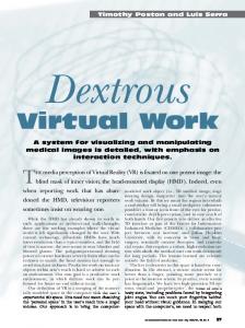
The Hospice of the Grand St. Bernard has an extraordinary location and history. The monastery is located atop the Grand St. Bernard Pass 2472 meters above sea level. The summit of the pass forms the border between Italy and Switzerland and has been a major route between Northern Europe and the Italian Peninsula since the mesolithic period [Hun2005]. Harsh weather frequently isolates the Pass and has made its crossing a perilous and often deadly activity. The valley descending from the summit on the Swiss side is named in french ‘Combe des Morts’, in english, ‘Valley of Deaths’. Today the road over the Pass is open for only three months a year and the average annual snowfall exceeds fifteen meters. The monastery was founded almost one thousand years ago by St. Bernard. Beginning with a single one room rock shelter, St. Bernard began a tradition of refuge and welcome continued by the Augustinian monks of his order today. The Monastery possesses an extensive archeological collection excavated from the Grand St. Bernard Pass including material from a 17th century BCE bronze age tomb. The numismatic collection, ranging from the time of Alexander the Great to the 19th century CE, includes six hundred Celtic, two hundred Roman Republic, and fifteen hundred Roman Imperial coins. 6. PTM Acquisition and Processing We designed a manual, easily transportable, and low cost system. The system consisted of a light position template, fiber optic directional light source, and computer controlled camera. The light position template indicated twenty four known spatial locations in a hemispheric array surrounding the coin. The camera, an 11 megapixel Canon 1Ds, was positioned at the apex of the hemispheric light array and triggered remotely by computer.The light was moved by hand to each of the twenty four positions and a corresponding image captured. The coins were photographed on a calibrated 18% Kodak gray card and care was taken to isolate the coin and card from the surrounding template to mute vibration. The set of twenty four constituent PTM light direction images for each face of the coins required an average of 30 minutes to captureProcessing the images and Archiving the PTM building process Each constituent PTM light direction image was captured in RAW format. Capture One software was used to set white balance for each group and convert the RAW images into 16
Figure 4: PTM System: 1) 5500K Solarc illuminator 2) liquid light guide 3) optical condenser and diffusing unit 4) 50 mm Canon FD lens 5) height indexed light stand 6) Template 7) 18% gray card 8) Canon 1Ds 9) Canon 100 mm macro lens 10) Dual focusing sliders 11) tripod with extension arm 12) Ever useful gaffers tape The original Raw images and their conversion settings were archived as were the Photoshop batch processes, the light position file, associating images with light position coordinates, and the PTM-Fitter command line string, indicating the specific set of PTM attributes employed. At the end of the process, each PTM possessed an associated archive enabling anyone to review the image processing employed to build it. The same information can be used for confirmatory replication. In this way the quality of the PTM image can be independently assessed 7. Results PTMs were captured of both sides of seven selected coins from the collection. These PTMs were bundled with the Java based Viewer written by Clifford Lyon [Lyo2004] and are displayed, with descriptions in French, on the website maintained by the Congregation of the Grand St. Bernard, in order to, in the words of the Congregation, “allow people to consult some of the seminal objects of our civilization” [GSBweb]. The PTMs have also been included in a Powerpoint presentation given to members of the Congregation and youth groups traveling over the Pass, again in the words
Mudge, Voutaz, Schroer, Lum / Reflection Transformation Imaging and Virtual Representations of Coins from the GSB of the Congregation, “to explain to them that they are part of a long chain of human beings which crossed the Alps going back millennia.” They are also displayed, with English descriptions, on the Cultural Heritage Imaging website [CHIweb2]. The coins from the Grand St. Bernard collection whose PTMs are featured in this paper are described below. 7.1 Silver Roman Republican Denarius
Figure 5: Denarius Obverse: Goddess Roma head right., denomination indicated by ’X’ left of head, ‘ROMA’ written on field at right. Reverse: Jupiter driving a Quadringa with Laurel branch above, ‘CN.DOMI’ in exergue. Struck in Rome 116-115 BCE, Silver, 3.91g, 20.6x19.4mm, Catalog Number: GSBf 617 7.2 Bronze Roman Imperatorial Aes depicting ‘Julian Star’
tus. It commemorates the divinization of Julius following his assassination in March of 44 BCE. The comet, the Sidus Iulium or Julian Star, appeared in July 44 BCE during the funnery games held to honor Julius following his assassination in March of that year and remained for a period of days. When it departed, historians relate that it was thought to carry the soul of Julius and was said to have been a sign of his divinity [RL1997]. Gold Merovingian Triens
Figure 7: Triens Obverse. Bust of Merovingian ruler wearing pearl diadem, partial legend ‘OMUIT’ in field. Reverse: Latin cross with “V’ and ‘II’ surrounded by a crown of pearls, remnant of ‘ACAUNO FIT’ in field. Minted at Agaune (St. Maurice), Switzerland, Merovingian, Clotaire II (613-628 CE) or Dagobert I (628-638 CE), Gold, 1.14g, 11.3x11.0mm. Catalog Number: RGa F4C1. Only known example. 7.3 Evidence of complete surface information for gold coins Our work confirmed previous observations that PTMs were able to robustly document the surfaces of highly specular materials and specifically gold.
Figure 6: Aes Obverse: Julius Caesar left, Octavian, Caesar’s adopted son (later Augustus), right, Sidus Illium comet above their heads, IMP CAESAR DIVI F DIVI IVLI in field. Reverse: Prow of Roman ship adorned with dolphin. Minted in Lyon, France, Imperatorial period, (39 or 36 BCE), Bronze, 21.43g, 30.8x30.2mm. Catalog Number: GSBf 698. One of four known examples. This coin was issued by Octavian, the adopted son of Julius Caesar, who became the first roman emperor Augus-
Figure 8 shows two images of the obverse of the Merovingian Triens. The image on the left of Figure 8 is one of the twenty four input images for the PTM. It clearly shows two areas, indicated with arrows, where specular reflections have caused data loss. The image on the right of Figure 8 is captured from the resultant PTM under specular enhancement and shows complete surface information for the areas in question Given a sufficient number of empirically captured incident illumination direction samples to generate accurately formed parametric geometry in light space, occasional instances of missing data due to shadows and specular highlights are replaced by accurately interpolated values. The presence of complete surface normal information in the
Mudge, Voutaz, Schroer, Lum / Reflection Transformation Imaging and Virtual Representations of Coins from the GSB PTM permits reflectance transformation operations on the entire virtual coin.
.
Figure 8: Specular Reflection 7.4 Data discernment advantages to reflectance transformation documentation Diffuse gain provides contrast enhancement that, in combination with a dynamically changing light direction, aids the perception of bas-relief morphology. Figure 9 shows two views with identical lighting. the image on the left is unenhanced. The image on the right employs diffuse gain. The additional contrast from the diffuse gain enhancement ‘brings out’ the subtleties of the Quadringa and horses’ form.
Figure 10: Unenhanced ‘Julian Star’
Figure 9: Diffuse Gain Enhancement The established utility of specular enhancement to disclose surface information, sometimes even invisible during direct physical examination, is of great value to the field of numismatics Figures 10 and 11 show two images of the coin commemorating Julius Caesar’s Funeral Games. The Comet is circled in its full context and then magnified. Due to heavy wear, there is significant abrasion of the coin’s surface features. In Figure 10, the coin is seen in its natural, primarily diffuse mode. In Figure 11, the coin is seen in its specular enhancement mode. The Specular enhancement mode shows, with superior clarity, the four rays of light surrounding the comet along with the triangular comets tail extending behind it at approximately the ‘five o’clock’ position.
Figure 11: ‘Julian Star’ with Specular Enhancement
Mudge, Voutaz, Schroer, Lum / Reflection Transformation Imaging and Virtual Representations of Coins from the GSB 8. Conclusions 8.1 PTMs provide an interactive experience of a more complete data set than traditional numismatic documentation Using PTM viewing software to interactively experience the virtual documentation of the coins, clearly demonstrates the value of reflection transformation imaging to the field of Numismatics. The ability to light coins from any desired direction permits features visible only from specific illumination directions to be seen. Areas which are obscured by shadows and bright reflections when lit from a given direction can be observed by changing the illumination direction. With a virtual PTM image, the traditional experience of examining a static photograph image is transformed into a dynamic process of intentional viewing, exploring, in an intuitive manner, a far richer data set. 8.2 PTMs offer a more informed and tool rich method to select and generate images that convey numismatic ideas. The ability of maximum entropy analysis to disclose which PTM illumination directions provide the greatest amounts of information in combination with specular enhancement, diffuse gain, and the flexibility of dynamic illumination direction, enables scholars and other users to determine which image or set of images will most effectively communicate their ideas. The PTM image can be analyzed both algorithmically and pragmatically to find the most advantageous combination of illumination angle(s) and enhancement effect(s) that illustrate the characteristics under discussion. The optimized image(s) can then be digitally captured and included in the desired communication medium. This offers significant advantages over the fundamentally arbitrary and editorial nature of even the most aesthetically accomplished traditional single image photography. 8.3 PTMs as 3D Textures with normals for virtual coins The ability of PTMs to document numismatic surfaces without data loss, generate surface normal information, and, through the use of reflection transformation functions, to enable 3D virtual representations to carry and communicate additional useful information, strongly recommends their use as textures for 3D virtual coins. 8.4 The Advantages of PTMs Captured in combination with Structured Light Range Data Our exploration of 2D and 3D reflection transformation imaging documentary applications indicate a strong affinity
between structured light 3D acquisition and reflection transformation imaging with PTMs. Variants of this relationship between structured light and PTMs also exist between structured light and other methods of measuring bidirectional reflectance functions (BRDFs) which capture normal vector information. The following advantages of this affinity suggest that very high quality numismatic documentation can be produced through the joint application of these techniques. This opportunity for the generation of high quality documentation may exist in other cultural heritage applications and inform the discussion of empirically acquired 3D virtual representations generally. The shape information contained in PTMs permits the use of less dense geometric descriptions. As was mentioned previously in the discussion of PTMs and photometric stereo [BMMR2002] and our 3D work with cuneiform tablets [Mud2004], the presence of empirically derived per pixel surface normal information serves as an excellent bump map. When registered and anchored to a surface in cartesian space, the normal information present in PTMs offer a densely sampled surface description that can span a less densely sampled, structured light acquired, geometry. When a denser geometric description is desired, a structured light system that generates per-pixel range data can be employed. Many such systems exist and examples of such structured light systems can be found in [RBMT1998], and [STY*2003]. Multiple scans can be aligned, merged, and full model texture maps synthesized using software such as [CCG*2003]. Each photographic structured light pixel generates information containing a Cartesian positional X,Y,Z triplet. When used in conjunction with a PTM acquisition system, the generated PTM image has a corresponding pixel possessing an R,G,B color triplet, a surface normal vector, and implied knowledge of any surface inter-reflection, subsurface scattering, and self-shadowing effecting the pixel. Given the registration between the pixels of the structured light source image and PTM source image, the surface normal information can be analyzed in combination with the surface range information to produce more precise 3D geometry [NRDR2005]. As have seen, when geometry in Cartesian space is generated from BRDF or PTM surface normal data, it is subject to low frequency (over relatively large distances) warping but can be highly accurate at high frequencies (over relatively small distances). On the other hand, scanned range data, whether from structured light or other sources, is well known to be quite accurate at the low frequencies but possess high frequency noise which distorts the location of surface points by a distance which is related to the scan’s sample density. The more points acquired in a square millimeter surface area, the smaller the distance positional data will be distorted by noise. Combined analysis of registered normal and range data sets uses the best information from both worlds to create a synthesized result corre-
Mudge, Voutaz, Schroer, Lum / Reflection Transformation Imaging and Virtual Representations of Coins from the GSB sponding more closely with the ‘real’ world documentary subject than either constituent data set alone. The combination of structured light scanning and PTM texture generation and the resulting geometry/texture relationship creates an empirically robust virtual representation. Structured light geometry and PTMs are inherently registered. This inherent registration increases the evidential reliability of the virtual representation because an explicit and necessary relationship exists between surface range data and color/normal vector information. The ability to refine surface shape through analysis of range and normal information sets acts as a cross-check on the coherence of the data and adds to evidential reliability. The archiving and association of image generation process history provides the in depth analysis and possibility of replication necessary to evaluate the documentary images’s quality. In turn, this evidential reliability accelerates the widespread acceptance and use of virtual representations by cultural heritage workers in their professional activities.
brated capture and display of PTMs and multi-row object movies, creating an encompassing environment for aligning sets of PTMs with varying viewpoints. Integrated 3D geometry derived from visual hulls extracted from these object movies will also be explored. We also plan to capture numismatic and other material using a combined PTM/ structured light apparatus. 10. Acknowledgements The generous assistance of Tom Malzbender, Dan Gelb, and HP Labs, made this work possible. The congregation of the Hospice of the Grand St. Bernard offered their welcome, encouragement, vision, and production help. Dr. Patrick Hunt, Director of the Stanford Alpine Archaeology Project, provided important archeological analysis and logistical aid. Thanks to the Cultural Heritage Imaging Board of Directors, supporters, and volunteers for funding and labor. 11. References
8.5 Summary 2D PTMs of coins communicate as much, if not more, visual information as direct physical examination. The ease of their digital communication overcomes numismatic access and display limitations. This information can be algorithmically analyzed and pragmatically explored using an enhancement tool kit to create the most useful images to convey numismatic ideas. Through digital communication, ancient coins from the very remote, and often snow-bound collection of the Hospice of the Grand St. Bernard have become available to the whole world. This successful proof of concept project can lead to wider access of other numismatic collections. The integration of PTMs with per-pixel structured light range data will lead to more accurate 3D virtual coins which can be examined using the PTM enhancement tool kit. The evidential reliability of both 2D PTM and 3D PTM/ Structured light virtual representations of coins can encourage the adoption and development of similarly empirically accountable virtual imaging methods in other cultural heritage areas of study and the field of 3D object acquisition generally. 9. Future Work We have built an automatic thirty two light fiber optic PTM capture device able to document coins, and with adaptation, larger objects. It can limit photon damage through control of the illumination wavelength band, enabling the documentation of wax and lead seals on ancient documents and other fragile, light sensitive materials. We intend to document cultural heritage objects through the camera cali-
[CCG*2003] Callieri, M., Cignoni, P., Ganovelli, F., Montani, C., Pingi, P., Scopigno, R. 2003. VCLabb’s Tools for 3D Range Data Processing VAST 2003, Virtual Reality, Archaeology, and Intelligent Cultural Heritage, Eurographics Symposium Proceedings. pp. 13-22. [CIG*2003] Cosmas, J., Itegaki, T, Green, D., Joseph, N., Van Gool, L., Zalesny, A., Schindler, K., Vanrintel, D., Leberl, F., Grabner, M., Karner, K., Gervautz, M., Hynst, S., Waelkins, M., Vergauven, M., Pollefeys, M., Cornelis, K., Vereenooghe, T., Sablatnig, R., Kampel, M., Axell, P., Meyns, E., 2003. Providing Multimedia Tools for Recording, Reconstruction, Visualization and Database Storage/ Access of Archeological Excavations. VAST 2003, Virtual Reality, Archaeology, and Intelligent Cultural Heritage, Eurographics Symposium Proceedings pp. 166-167. [CHIweb1] http://c-h-i.org/examples/3d/3d_tetra_obj.html [CHIweb2] http://c-h-i.org/examples/ptm/ptm.html [FLAARweb] FLAAR Information network, http://www.flatbed-scanner-review.org/ gold_coin_collecting_scanner/collecting_silver_coins.html. [GSBweb] http://www.gsbernard.ch/histoire/musee.htm [HBMG2002] Hammer, O., Bengston, S., Malzbender, T., Gelb, D. August 2002. Imaging Fossils Using Reflective Transformation Imaging and Interactive Manipulation of Virtual Light Sources. Palaeontological Association. Palaeontologia Electronica, 2002, issue 1
Mudge, Voutaz, Schroer, Lum / Reflection Transformation Imaging and Virtual Representations of Coins from the GSB [Hob1981] Hoberman, G., 1981. The Art of Coins and their Photography. Spink and sons Ltd. in cooperation with Lund Hunphies Publishers Ltd. ISBN 0853314500, pp. 323-363 [HPLweb]http://www.hpl.hp.com/research/ptm/ [Hun2005] Hunt, P., 2005. Archaeology and History of the Great St. Bernard Pass. L'Erma di Bretschneider, Rome, publisher. ISBN pending. [KSK1988] Klette, R., Schluns, K., Koschan, A. 1988. Computer Vision, Chapter 8: Photometric Stereo. Springer Verlag, publisher. ISBN 981-3083-71-9, pp. 301-345 [Lyonweb] http://materialobjects.com/ptm/ [MGW2001] Malzbender, T., Gelb, D., and Wolters, H. 2001. Polynomial texture maps. Proceedings of ACM Siggraph, 2001 [MGWZ2000] Malzbender T., Gelb, D., Wolters, H., and Zuckerman, B. 2000. Enhancement of shape perception by surface reflectance transformation. Hewlett-Packard Technical Report HPL-2000-38. [MO2005] Malzbender, T., Ordentlict, E. 2005. Maximum Entropy Lighting for Physical Objects. Hewlett-Packard Technical Report HPL-2005-68. http://www.hpl.hp.com/ personal/Tom_Malzbender/papers/papers.htm [[Mor2003] Morton, S. Feb. 2003. Forensic Document Examiner for the San Francisco Police Criminalistics Laboratory, 850 Bryant Street, San Francisco, Ca 94103. Presentation to the Criminalistics Section of the American Academy of Forensic Sciences. [Mud2004] Mudge, M. 2004. SIGGRAPH 2004 Conference Presentations, Web Graphics/Special Sessions/Panels, Cultural Heritage and Computer Graphics Panel. Soma Media, publisher, ISBN1-58113-950-X [NGweb] National Gallery, London. http://www.tate.org.uk/collections/ptm/technical.htm [NRDR2005] Nehab, D., Rusinkiewics, S., Davis, J., Ramamoorthi, R., 2005. Efficiently Combining Positions and Normals for Precise 3D Geometry. ACM Transactions on Graphics, Siggraph, 2005. http://www.cs.princeton.edu/ gfx/pubs/Nehab_2005_ECP [Pho1975] Phong, B.T. 1975. Illumination for computer generated images. Communications of the ACM, 18(6):311317. [RBMT1998] Rushmeier, H., Bernardini, F., Mittleman, J., Taubin, G. 1998. Acquiring Input for Rendering at Appro-
priate Levels of Detail: Digitizing a Pieta. Rendering Techniques ’98, pp. 81-92. [BMMR2002] F. Bernardini, I. Martin, J. Mittleman, H. Rushmeier, G. Taubin. Building a Digital Model of Michelangelo's Florentine Pieta'. IEEE Computer Graphics & Applications, Jan. 2002, pp. 59-67 [RL1997] Ramsey, J., Licht, A. 1997. The Comet of 44 B.C. and Caesar’s Funeral Games. American Philological Association American Classical Studies, Number 39. Scholar’s Press, Atlanta Ga., publisher. [STY*2003] Stumpful, J.,Tchou, C., Yun, N., Martinez, P., Hawkins, T., Jones, A., Emerson, B., Debevec, P. 2003. Digital Reunification of the Parthenon with its Sculptures. VAST 2003, Virtual Reality, Archaeology, and Intelligent Cultural Heritage, Eurographics Symposium Proceedings. pp. 41-50. [WD2003] Wang, J., Dana, K., A Novel Approach for Texture Shape Recovery. ICCV 2003, Volume 2, pp. 1374-80. [WGT*2005] Wenger, A., Gardner, A., Tchou, C., Unger, J., Hawkins, T., Debevec, P., 2005. Postproduction Relighting and Reflectance Transformation with Time-Multiplexed Illumination. Proceedings of ACM Siggraph, 2005. http:// gl.ict.usc.edu/research/LS5/index-s2005.html