3328
OPTICS LETTERS / Vol. 34, No. 21 / November 1, 2009
Refractive index sensor based on a microhole in single-mode fiber created by the use of femtosecond laser micromachining Ying Wang,1,2 D. N. Wang,1,* Minwei Yang,1 Wei Hong,1,2 and Peixiang Lu1,2 1
Department of Electrical Engineering, The Hong Kong Polytechnic University, Hung Hom, Kowloon, Hong Kong, China 2 Wuhan National Laboratory for Optoelectronics, Huazhong University of Science and Technology, Wuhan 430074, China *Corresponding author:
[email protected]
Received August 7, 2009; revised September 25, 2009; accepted September 28, 2009; posted October 5, 2009 (Doc. ID 114919); published October 27, 2009 A compact in-fiber refractive index (RI) sensor is presented that is based on a microhole created in a conventional single-mode fiber by the use of femtosecond laser micromachining. The transmission properties of such a device with a microhole of different diameters have been investigated in the wavelength region of 1500–1600 nm and in the RI range of 1.30–1.45. It is found that the relationship between the transmission and the RI is critically dependent on the size of the microhole in the fiber core region. The highest resolution obtained is 6.70⫻ 10−5, in the RI range of 1.37–1.42, when the microhole diameter is ⬃8 m, close to the fiber core size. The in-fiber RI sensor developed in this work is easy to fabricate and can be used to implement temperature-independent measurements. © 2009 Optical Society of America OCIS codes: 060.2370, 320.7140, 130.6010.
Fiber-based refractive index (RI) sensors are attractive means for chemical, biomedical, and environmental monitoring applications because of their compactness, light weight, convenience for in situ and/or remote measurements, and many other advantages provided by the optical fibers. Many in-fiber devices have been exploited for RI sensing by the use of conventional single-mode fibers (SMFs), tapered fibers, and photonic crystal fibers (PCFs), such as fiber Bragg grating (FBG), long period grating (LPG), and in-fiber interferometers, among others [1–6]. However, these RI sensors are either expensive or highly sensitive to environmental temperature changes [6]. The femtosecond laser has been a powerful tool for high precision ablation in a variety of materials including ceramics, metals, polymers, and transparent materials such as silica glass [7,8], owing to its high intensity over ultrashort pulse duration and good spatial resolution. Moreover, the materials can be removed in a fast and clean way, with negligible heat affected zones, thus avoiding any significant damage to the underlying substrate [9,10]. In recent years, microchannels, microslots, and Fabry–Perot interferometers in SMFs have been fabricated by the use of femtosecond laser processing together with chemical etching, which can be effectively utilized for RI sensing with an improved temperature insensitivity and a potentially low cost [11–14]. In this Letter we report a compact in-fiber RI sensor based on a microhole in a conventional SMF by direct femtosecond laser pulse ablation without chemical etching. Such a device is easy to fabricate, exhibits a good linearity in a broad RI region, has a high resolution, and can be effectively used to implement a temperature insensitive measurement. In the experiments carried out, femtosecond laser pulses 共 = 800 nm兲 of 120 fs at a repetition rate of 1 kHz were focused onto the fiber (SMF-28) by a 10⫻ 0146-9592/09/213328-3/$15.00
objective lens with a NA value of 0.25 and a working distance of 7 mm, and the pulse energy used was 11 J. The fiber core diameter was 8.2 m, with a nominal effective index of 1.4682 (at 1550 nm). The fiber was mounted on a three-axis translation stage that was carefully adjusted so that the upper surface of the cladding was located at the beam waist. A broadband light source connecting the fiber at one end and an optical spectrum analyzer (OSA) with a resolution of 0.01 dB at the other end was used to perform a real-time measurement. Three types of microholes with different values of diameter D (defined at the core–cladding interface) were fabricated with laser irradiation times of 5, 15, and 150 s, respectively, controlled by a mechanical shutter. When irradiated with femtosecond pulses, the material in the focal volume is ionized through multiphoton ionization (MPI) or tunneling ionization (TI), before the ablation occurs at the target surface. This process is independent of the initial defects in the material; thus the drilling process is quite stationary. Two samples for each type were fabricated to verify the repeatability of the device, marked as S-6a and S-6b, S-8a and S-8b, and S-11a and S-11b with D measured as ⬃6.2 and 6.1, 7.9 and 8.0, and 11.0 and 11.0 m, respectively. The fiber device created was subsequently immersed into a series of RI liquid samples (from Cargille Laboratories) to test its response to different hole indices. The RI of the liquids used was in the range of 1.30–1.45 (at 589.3 nm). Each time after the sample was measured, the device was rinsed with methanol carefully until the original spectrum (corresponding to the hole index of 1.0) could be restored and no residue liquid was left inside the microhole. Figures 1(a)–1(c) show the normalized transmission spectra of S-6a, S-8a, and S-11a filled with different indices. The transmission of S-6a shows only a © 2009 Optical Society of America
November 1, 2009 / Vol. 34, No. 21 / OPTICS LETTERS
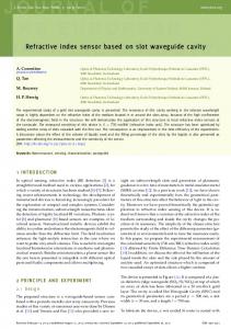
Fig. 1. (Color online) Transmission spectra of the microholes of different diameters, filled with RI fluids of 1.30– 1.45. (a), (b), and (c) show the normalized transmission versus wavelength of samples S-6a, S-8a, and S-11a, respectively; (d) demonstrates the normalized transmission versus microhole index. The insets of (a)–(c) represent the morphology of S-6a, S-8a, and S-11a (side view), and the diameter of the microholes at the fiber core and cladding interface, respectively. The corresponding microhole diameters for S-6a and S-6b, S-8a and S-8b, and S-11a and S-11b are 6.2, 7.9, and 11 m, respectively.
very small change with the increase in wavelength as shown in Fig. 1(a). A more complex situation happens for sample S-8a, whose diameter is close to the core size. It can be observed from Fig. 1(b) that the transmission spectra exhibit small fluctuations while being not monotonic with respect to the RI change. When D is further increased to 11 m (sample S-11a), the transmission is essentially unchanged with the wavelength variation as shown in Fig. 1(c). As the relationship between the transmission and the microhole indices cannot be observed in a straightforward way, the curves (at 1550 nm) of the six samples were plotted in Fig. 1(d), from which it can be observed that the transmission of S-6a experiences a sharp increase with the increase in the RI in the range of 1.31–1.41, at the rate of 71 dB/ refractive index unit (RIU), where a good linear relationship between the transmission and the RI can be maintained. The RI resolution of S-6a obtained in the index range of 1.31–1.41 is 1.40⫻ 10−4. The transmission behavior of S-6b is nearly the same as that of S-6a. The transmission of S-8a gradually decreased from ⫺4.83 to ⫺8.20 dB in the RI range of 1.30–1.35 at the rate of 67 dB/RIU, and it reaches the minimum at the index level of 1.36. The transmission is then rapidly and linearly increased in the RI range of 1.36–1.42 at the rate of 110 dB/RIU. The sample S-8b exhibits a similar transmission behavior as that of S-8a, but the RI value at the minimum transmission is 1.37. It is worth noting that S-8b provides the highest RI resolution of 6.70⫻ 10−5 in the index range of 1.37–1.42 at 1550 nm in our experiments, which implies that the transmission characteristics are very sensitive to D for the hole diameter of around 8 m. The transmissions of S-11a and S-11b exhibit an ex-
3329
cellent linearity in the whole RI range of 1.30–1.45 with a small slope of 27 dB/RIU. The light transmission behavior for the microholes of different diameters may be explained by the use of Fig. 2(a), where a constant transmission coefficient is assumed for all the RI solutions. When D ⬍ core size, part of the light passes through the microhole and dissipates owing to the small incident angle t1 at the core–cladding interface. When D is close to the core size, no light can be directly guided in the fiber core without passing through the microhole; thus the transmission is critically dependent on the RI of the hole as will be discussed. If D ⬎ core size, the light refracted from the hole–core surface will be guided owing to the large incident angle t3 at the interface, thus reducing the transmission loss. The light transmission behavior for the microhole close to the core size with different RIs may be explained by simple ray optics as shown in Fig. 2(b), where nh and ncore are the RIs of the hole and the fiber core, respectively, and nh ⬍ ncore. Assuming that the incident angle of light to the hole is smaller than the critical angle, when nh = n1 is small, the first refracted beam cannot be bounded in the core, but the second refracted beam may be guided. If nh is increased to a large value of n2, both the first and the second refracted beams will be dissipated, and the transmission loss becomes large. When nh is further increased to n3, the first refracted beam will be directly guided, although the second one is dissipated. The first refracted beam should have a higher intensity than the second one owing to the relatively low reflection at the hole–core interface; thus the transmission loss becomes small. It becomes clear from the above discussion that, with the increase in the RI, the transmission loss is first increased and then decreased and, as a result, a dip appears in the transmission curve within a certain RI region. Note that the transmission loss of the air-filled hole is lower than that of the 1.30 RI liquid-filled hole as shown in Fig. 1(a). Similar discussions could be made as mentioned before with the ray optics model shown in Fig. 2(b). When nh = nair (nair = 1.00 approxi-
Fig. 2. (Color online) Simple explanation of the transmission behavior of the microhole (a) with different hole diameters and (b) of the fiber core size with different RIs.
3330
OPTICS LETTERS / Vol. 34, No. 21 / November 1, 2009
mately), the second refracted beam may be guided and partially compensate the output power, although the first refracted beam cannot be bounded in the core. If nh is increased to 1.30, both the first and the second refracted beams will be dissipated, resulting in a larger transmission loss. To investigate the temperature response of the device, a microhole with a size of 6.2 m was immersed into the water and heated in a column oven from 30 ° C to 70° C. Figure 3 shows the measured transmission versus temperature. By subtracting the contribution from the water-RI change [15], the calibrated curve exhibits only small fluctuations of within 0.03 dB. The maximum measurement error induced by the temperature cross sensitivity was less than 4.0⫻ 10−4 within the temperature range employed. This confirms the capability of the device to implement a temperature-independent measurement. It can be observed from Figs. 1(a)–1(c) that the transmission of the microhole based device is highly index dependent but only slightly wavelength dependent. This is owing to the relatively small size of the microhole, and the corresponding Fabry–Perot effect created fringe spacing is over a few hundreds of nanometers. The hole diameter in the core region, where the scattering and multiple reflections are taking place, plays a crucial role in the determination of the measurement resolution in different RI regions. Meanwhile, the roughness of the hole wall created during the laser processing process would cause fluctuations in the transmission spectra as shown by the ripples in Fig. 1(b). Such fluctuations would be reduced if the laser processing parameters could be optimized, possibly by using lower pulse energy and longer exposure time. The influence of the hole depth on the transmission is not so significant as far as the depth reaches the entire cross section of the fiber core. However, a small hole depth helps one to enhance the robustness of the fiber device when compared with the microchannel passing through the entire cross section of the fiber [11]. Thus, by selecting the appropriate diameter and the smallest possible depth of the microhole, the measurement resolution and the robustness of the in-fiber RI sensor proposed can be ensured.
Fig. 3. (Color online) Temperature response of the normalized transmission of the microhole filled with water before calibration (black squares) and after calibration (red triangles).
In conclusion, we have demonstrated a compact RI sensor based on a microhole in a conventional SMF fabricated by direct femtosecond laser pulse ablation. The transmission properties of such a fiber device have been investigated within the wavelength region of 1500–1600 nm and in the RI range of 1.30–1.45. It is found that the microholes of different diameters show different RI sensitivities in the different index ranges, and the highest resolution obtained is 6.70 ⫻ 10−5, in the index range of 1.37–1.42, corresponding to the microhole diameter of ⬃8 m. The transmission behavior of the device was also investigated with a simple 2D finite-difference time domain (FDTD) model, and the numerical results are in good agreement with those obtained in the experiments. The RI resolution can be further improved by selecting the appropriate microhole diameter and/or increasing the number of microholes with the appropriate separation along the fiber length. Moreover, when compared with the microchannel passing through the whole cross section of the fiber, the robustness of the device can be guaranteed by limiting the microhole depth within the fiber core region. The microhole based in-fiber RI sensor developed in this work is easy to fabricate and exhibits a good temperatureindependent measurement capability, which is important for practical applications. This work was supported by Hong Kong Special Administration Region Government through a GRF grant PolyU 5306/08E. References 1. A. Iadicicco, A. Cusano, A. Cutolo, R. Bernini, and M. Giordano, IEEE Photon. Technol. Lett. 16, 1149 (2004). 2. J. F. Ding, A. P. Zhang, L. Y. Shao, J. H. Yang, and S. He, IEEE Photon. Technol. Lett. 17, 1247 (2005). 3. P. Polynkin, A. Polynkin, N. Peyghambarian, and M. Mansuripur, Opt. Lett. 30, 1273 (2005). 4. Z. Tian, S. S. H. Yam, and H. P. Loock, Opt. Lett. 33, 1105 (2008). 5. D. K. C. Wu, B. T. Kuhlmey, and B. J. Eggleton, Opt. Lett. 34, 322 (2009). 6. R. Jha, J. Villatoro, G. Badenes, and V. Pruneri, Opt. Lett. 34, 617 (2009). 7. R. Osellame, V. Maselli, R. Martinez Vazquez, R. Ramponi, and G. Cerullo, Appl. Phys. Lett. 90, 231118 (2007). 8. R. R. Gattass and E. Mazur, Nat. Photonics 2, 219 (2008). 9. S. Nolte, C. Momma, H. Jacobs, A. Tunnermann, B. N. Chichkov, B. Wellegehausen, and H. Welling, J. Opt. Soc. Am. B 14, 2716 (1997). 10. E. N. Glezer and E. Mazur, Appl. Phys. Lett. 71, 882 (1997). 11. Y. Lai, K. Zhou, and I. Bennion, Opt. Lett. 31, 2559 (2006). 12. K. Zhou, Y. Lai, X. Chen, K. Sugden, L. Zhang, and I. Bennion, Opt. Express 15, 15848 (2007). 13. Z. L. Ran, Y. J. Rao, W. J. Liu, X. Liao, and K. S. Chiang, Opt. Express 16, 2252 (2008). 14. T. Wei, Y. Han, Y. Li, H. Tsai, and H. Xiao, Opt. Express 16, 5764 (2008). 15. P. Shiebener, J. Straub, J. M. H. Levelt Sengers, and J. S. Gallagher, J. Phys. Chem. Ref. Data 19, 677 (1990).