Regression Testing Based-on Slicing of Component-based Software Architectures Jaiprakash T Lalchandani
[email protected]
R Mall
[email protected]
Department of Computer Science and Engineering Indian Institute of Technology Kharagpur Kharagpur WB, INDIA
ABSTRACT
(ADLs) provide notations to represent the architectural model of a software system. Notable ADLs proposed in the literature include Acme [1], Rapide [2], Unicon [3], and Wright [4]. Software development in the past has been code-based with little emphasis on software architecture. With increased complexity of software products, and requirement for multi-platform adaptability, software architecture has become a key issue in managing the early phases of software life cycle. For large programs, even the software architecture becomes large and complex. For such large architectures, development of techniques to support understanding, testing, re-engineering, maintenance, and reuse of software architectures has become an important issue [5]. In this context, researchers have proposed the use of program slicing techniques to decompose large architectures into manageable portions that can help in understanding, analysis, and reliability prediction of large architectures. Besides, architecture slicing has also been used for computation of various types of metrics associated with software architectures. Program slicing, originally introduced by Weiser [6], is a decomposition technique that extracts program elements related to a particular computation. A program slice consists of those parts of a program that may directly or indirectly affect the values computed at some program point of interest, referred to as a slicing criterion. The slicing criterion is a pair (s,V), where s is a statement and V is a set of variables defined or used at s, and a slice consists of only program statements. Traditional slicing techniques cannot be directly used to slice software architectures. Traditional slicing has been studied primarily in the context of conventional programming languages, where slicing is typically performed using dependence graph representation of a program. This intermediate representation primarily captures the statements, and the dependence relationships among statements. It is usually performed solely based on data and control dependency relationships existing among program statements. The basic elements of software architectures are components and their interconnections. Besides definition-use relationships, the elements of ADL support description of more complex relationships. On the other hand, traditional slicing is performed using data and control dependencies. Therefore, to perform slicing at the architecture level, appropriate slicing notions for software architectures must be defined with new types of dependence relationships using components and connectors [7, 8, 9]. Applying slicing technique to software architectures can benefit software development in two main ways. The first one concerns maintenance of a component-based software. By using slicing tools on an architectural description, we can determine which components might be affected when a given component is modified. Second, architectural reuse can be facilitated. While reuse of code is
We propose an efficient dynamic slicing algorithm for componentbased software architectures. We first transform a software architecture into an intermediate representation which we have named architecture component dependence graph(ACDG). Our slicing algorithm is based on marking and unmarking the in-service and outof-service edges on an ACDG as and when dependencies arise and cease on occurrence of events. We use the computed dynamic architectural slices to select test cases for regression testing of component based systems. One important advantage of our approach is that a slice is available for use even before a request for a slice is made. This appreciably reduces the response time of slicing commands, and help regression testing. We show that our architectural slicing algorithm is more time and space efficient than the existing algorithms. We also briefly discuss a prototype tool SRTWA(Slicerbased Regression Testing of Wright Architectures) which we have developed to implement our algorithm.
Categories and Subject Descriptors H.4 [Information Systems Applications]: Miscellaneous; D.2.11 [Software Engineering]: Software Architectures—Languages(e.g., description, interconnection, definition); D.2.2 [Software Engineering]: Design Tools and Techniques—Object-oriented design methods
General Terms Design
Keywords software architecture, ADL, component-based systems, architectural slicing, regression testing
1.
INTRODUCTION
Architecture of a software system defines its high level design structure. It allows an architect to reason about system properties at a high level of abstraction. Architectural Description Languages
Permission to make digital or hard copies of all or part of this work for personal or classroom use is granted without fee provided that copies are not made or distributed for profit or commercial advantage and that copies bear this notice and the full citation on the first page. To copy otherwise, to republish, to post on servers or to redistribute to lists, requires prior specific permission and/or a fee. ISEC’08, February 19-22, 2008, Hyderabad, India. Copyright 2008 ACM 978-1-59593-917-3/08/02 ...$5.00.
67
important, reuse of software design and patterns are expected to offer greater productivity benefits, and reliability enhancements. This is especially true of large software products. Contemporary software architectures are large, complex and eventdriven. Such architectures are difficult to understand and debug. To help understand these architectures, development of efficient slicing techniques is important. These techniques can help reduce the effort required for understanding and analysis of software architectures. However, efficiency of the slicing techniques is an important concern due to the large sizes of modern software architectures. In this context, we propose an efficient dynamic slicing algorithm for software architectures. Our algorithm uses a modified form of program dependence graph (PDG) [10] as the intermediate representation. We have named this graph Architecture Component Dependence Graph (ACDG). Our proposed dynamic slicing algorithm for software architectures represents various types of dependencies as service dependencies among components contributing to the dynamic slice. A service dependence represents how a component provides a service to the other components and how it gets services from other components. Our slicing algorithm takes as input an architectural description in Wright ADL [4]. In order to compute a slice of an architecture, we first construct an ACDG to explicitly represent various types of dependencies in an architecture. Our slicing algorithm is based on updating these statically identified dependencies as marked [11, 12, 13] in-service and out-of-service edges, as and when the dependencies arise and cease. The rest of the paper is organized as follows. The next section reviews the related work. Section 3 presents basic definitions and notations that have been used in our algorithm. Our intermediate representation ACDG is discussed in Section 4. Section 5 presents our algorithm for computing a dynamic architectural slice along with an example to illustrate the working of our algorithm. Section 6 discusses how the architectural slices can be applied to the regression testing of component-based systems. Section 7 briefly discusses a prototype tool SRTWA(Slicer-based Regression Testing of Wright Architectures) which we have developed to implement our algorithm. Section 8 compares our work to the related work and Section 9 concludes the paper.
2.
sets of related elements contained in the dependence table are used to construct chains of dependent elements. This illustrates the utility of chaining, by showing how the technique can be applied to architecture specifications based on Rapide ADL [2]. Stafford et. al. [15] report application of dependence analysis to software architecture descriptions. Zhao [8] investigated a new dependence analysis technique, called architecture dependence analysis to support software architecture development. Zhao’s technique is based on analyzing the high level architecture of a software system given in Acme ADL. In order to perform architectural dependence analysis, his method captures various types of dependencies that exist in an architectural description. The considered dependencies arise as a result of dependence relationships existing among ports and/or roles of components and/or connectors. These identified dependencies are then represented using a software architectural dependence graph(SADG). The SADG of an architectural description is an arc-classified digraph whose vertices represent the ports of components and roles of the connectors in the description, and arcs represent the dependence relationships in the description. Though his work explores the use of Acme ADL, the presented approach on architecture dependence analysis has been shown to be independent of any specific ADL. However, they also show that any specific implementation of an architectural dependence analysis tool would be ADL dependent, and would differ from one ADL to another. Zhao introduced a static architecture slicing technique [17], which operates by removing unrelated components and connectors, and ensures that the behavior of a sliced system remains unaltered. Zhao’s work uses a SADG introduced earlier in [8] to explicitly represent various types of dependencies in an architectural description of a software system. The work reported by Zhao in [7] is an extension of his earlier work reported in [17, 8] and is based on Wright ADL. Kim introduced an architectural slicing technique called dynamic software architecture slicing(DSAS) in [19]. DSAS computes a dynamic slice by representing the run-time behavior of those parts of a software architecture that are selected according to a particular slicing criterion specifying a set of resources and their values. Kim’s work is able to generate a smaller number of components and connectors in each slice as compared to [17]. This is especially true in the presence of a large number of ports and whose invocation might change the values of some variables, or the occurrence of certain events.
RELATED WORK
In this section, we briefly review the reported work on architectural slicing. Stafford et. al [14] reported a tool called Aladdin. It is based on a static dependence analysis technique called chaining which focuses on component interactions [15, 16]. Chaining is a process of applying dependence analysis algorithms to architectural descriptions in order to create sets of related components. It first creates an intermediate representation, and then a language-independent analysis is performed on this representation. It uses a table consisting of a group of cells to record the dependence relationships in an architecture. A cell in this table represents the relationships that can exist between a given pair of architectural elements. The columns in the table represent the dependencies in the relationship and the rows represent the source (or object) of dependence. For instance, if object x is dependent on object y, then the cell at column x and row y captures that relationship. A cell may reflect the existence of a direct relation, such as a remote function call, it may indicate sharing of data, it may indicate an interaction by means of event notification, or it may represent a combination of relationships between two objects. In general, for a given ADL, it is necessary to understand the various ways in which two architectural elements can be related so that the dependence table can be constructed. The
3.
DEFINITIONS AND NOTATIONS
In this section, we define some important terms that would be used to describe our methodology for slicing the architectures of component-based software. We assume that the terms components, ports, events, connectors, roles, attachments and configuration carry the same meaning and context as used with Wright ADL specification. Henceforth, we do not redefine them. Our definitions, and methodology are based on the following terminology: • A component node exists for every component instance, and a connector node exists for every connector instance in the ADL specification. • A role defines a point of connectivity between a connector and its environment. In other words, a role acts as an interface to a connector. • An attachment links a component port to a connector role.
68
We now briefly present the notations used by our methodology as follows:
can also be defined as a configuration. A software architecture is denoted by a symbol S . Using the notation for configuration, S = U C.
• We represent a component as Cn , where Cn ∈ CS A and CS A = {i C, Co ,i Co }. Cn indicates nth component of a system and CS A represents a set of component types used in a software architecture; i C denotes a component with only in-ports, Co denotes a component with only out-ports, i Co denotes a component having both in-ports and out-ports.
In case we have to represent two or more software architectures, we use a suffix i with S, thereby denoting two different architectures by the symbol S 1 and S 2 respectively. Definition 2. An Architecture Control Flow Graph (ACFG) GA is a 4-tuple (NA ,EA ,Start,Stop ) where each node Ci,k ∈ NA represents an instance of a component of the architecture S; while each edge e ∈ EA represents a potential control transfer among the component instances.
• We represent a port by Pmn , where Pmn ∈ PCom and PCom = {i P, Po }; Pmn indicates mth port of the nth component and PCom represents the set of all possible types of ports that a component can have; i P represents a port of type in-port and Po represents a port of type out-port.
The use of these notations has been illustrated through an example shown in Figure 1(a). Figure 1(b) shows an ACFG for the architecture description given in Figure 1(a).
−−→ • We represent a connector as CC i j , which symbolizes [Pmi { n P j ] meaning that there exists a path from mth out-port of ith component to nth in-port of jth component. Alternatively, a connector can be represented as a port pair {Pmi , Pnj } and Pmi ,Pnj ∈ PCom . A path or an interaction defined by a connector always involves two components, which are termed as participant components.
Configuration ADL_Example Component type_A Port takes_in [input rule] Port gives_out [output rule] Computation [component type_A specification] Component type_B Port takes_in [input rule] Port gives_out [output rule] Computation [component type_B specification] Component type_C Port takes_in [input rule] Port gives_out1 [output rule] Port gives_out2 [output rule] Computation [component type_C specification] Connector type_AB Role comp_A [component type_A rule] Role comp_B [component type_B rule] Connector type_BC Role comp_B [component type_B rule] Role comp_C [component type_C rule] Connector type_CB Role comp_C [component type_C rule] Role comp_B [component type_B rule] Connector type_CA Role comp_C [component type_C rule] Role comp_A [component type_A rule] Instances a1 : type_A a2 : type_A b : type_B c : type_C ab : type_AB bc : type_BC cb : type_CB ca : type_CA Attachments a1.gives_out as ab.comp_A b.takes_in as ab.comp_B b.gives_out as bc.comp_B c.takes_in as bc.comp_C c.gives_out1 as cb.comp_C b.takes_in as cb.comp_B c.gives_out2 as ca.comp_C a2.takes_in as ca.comp_A End ADL_Example
• We represent a role as Rmn where Rmn ∈ RCon and RCon = {i R, Ro }; Rmn denotes mth role of the nth connector and RCon represents the set of all possible types of roles for a connector; i R represents a role of type in-role and Ro represents a role of type out-role. A role that accepts data from an outport of a component is termed as an in-role and the role that delivers data to an in-port of a component is termed as an out-role. • We represent an attachment as [Pmi { Rnj ]. It means that there exists a path from the mth out-port of the ith component to the nth in-role of the jth connector. On the other hand, if there exists a path from a role of a connector to a component port, we can represent this attachment as [Rmi { Pnj ] meaning that there exists a path from mth out-role of ith connector to nth in-port of jth component. U • We represent a configuration as C where C denotes a configuration.
Start
(a)
type_A : a1
type_B : b
type_C : c
type_A : a2
Stop
(b)
Figure 1: An Example Architecture Description and its ACFG
In the context of an ADL, an instance of a component is an object of that component type. An instance i of a component Cn is denoted as Cn,i . A port m of instance i of component Cn is denoted as Pmn,i . Also, an instance of a connector is an object of type connector. −−→ −−→ An instance k of a connector CC i j is denoted as CC k−i j . A role m −−→ of instance k of a connector CC i j is denoted as Rmk−i j . A port m of instance i of component Cn linked with role n of instance k of −−→ connector CC i j represents an attachment and is denoted as [Pmn,i { Rnk−i j ]. For the connectivity between kth instance of component C x and Cy using the mth out-port of C x,k and nth in-port of Cy,k linked −−→ by connector CC k−xy with in-role a and out-role b, a two component configuration can be defined as, −−→ {Cx,k } ∪ {Cy,k } ∪ {CC k−xy } ∪ {Pmx,k { Rak−xy } ∪ {Rbk−xy { Pny,k }
Definition 3. Let GA be an ACFG and C x,i be a node that induces a request for a service (or an induced service node). A node Cy, j is said to be control dependent on C x,i , iff there exists a directed path P from C x,i to Cy, j such that, • None of the nodes in P (excluding Cy, j ) is an induced service node. • Cy, j post-dominates every node Cz,k , C x,i . • Cy, j does not post-dominate C x,i . Definition 4. Let D be the data associated with a software architecture S. A node [C x : C x,i ] of an ACFG GA is said to be a DefData(D) node, if the node [C x : C x,i ] defines or initializes the data D. The set DefDataSet(D) denotes the set of all DefData(D) nodes. Definition 5. Let D be the data associated with a software architecture S. A node [C x : C x,i ] of the ACFG GA is said to be a UseData(D) node, if the node [C x : C x,i ] uses the data D. The UseDataSet(D) denotes the set of all UseData(D) nodes.
We now present a few important definitions. Definition 1. A software architecture can be defined as a finite collection of inter-connected components. A software architecture
69
In order to construct the ACDG of a software architecture, we must identify all components and its instances involved in the system, and find all dependencies among these instances of components. The definition of an ACDG and a method of its construction have been discussed in Section 4.
4.
type_A : a1
type_AB : ab type_A : a2
ARCHITECTURE COMPONENT DEPENDENCE GRAPH(ACDG)
type_B : b
In this section, we define our intermediate representation ACDG and discuss how a software architecture can be represented using our notation.
type_BC : bc type_CA : ca type_CB : cb
Definition 6. An ACDG GC of an architecture S is a directed graph (NC ,EC ), where each node C x,i ∈ NC is a set of vertices that represents an instance of a component in S. An ACDG may contain the following types of edges: (i) control dependence edge (ii) data dependence edge (iii) communication dependence edge and (iv) event dependence edge. For C x,i , Cy, j ∈ NC , (Cy, j , C x,i ) ∈ EC iff any one of the following holds:
type_C : c
Instance of a Component Instance of a Connector Control Dependence Edge Data Dependence Edge Communication Dependence Edge Event Dependence Edge
• if Cy, j is control dependent on C x,i , it is represented by an edge called a control dependence edge.
Figure 2: An ACDG for the Example Architecture Description of Figure 1(a)
• if Cy, j is communication dependent on C x,i , it is represented by an edge called a communication dependence edge. • if Cy, j is event dependent on C x,i , it is represented by an edge called an event dependence edge.
Definition 9. Let (C x,i ,Cy, j ) be an outgoing edge of the ACDG GC . The edge (C x,i ,Cy, j ) representing a dependency of C x,i on node Cy, j is called a service edge , if this edge has been recently traversed to get some service either due to the control flow from Cy, j to C x,i or a data transfer from Cy, j to C x,i or a message request from Cy, j to C x,i or an event completion on some port of Cy, j resulting in a change of state of C x,i . An edge which is not an in-service edge is termed as an out-of-service edge. All the edges of an ACDG GC are marked as out-of-service edges on initialization.
• if Cy, j is data dependent on C x,i , it is represented by an edge called a data dependence edge. ACDG captures the static as well as dynamic dependencies. The static dependencies are those which do not vary with time, for eg. control dependencies. The dynamic dependencies change with time include data dependencies, communication dependencies, and event dependencies. Figure 2 shows the ACDG of the example architecture of Figure 1(a). The control dependencies among components do not vary with the choice of data and hence can be determined statically. Data dependencies, communication dependencies, service requests or which depend on completion of an event are dynamic and cannot be determined statically. We present a few more definitions before presenting our slicing algorithm.
Definition 10. A dynamic slice with respect to a slicing criterion [S, C x,i , Pmx,i [ξ], D] is denoted as Dynamic_Slice(S, C x,i , Pmx,i [ξ], D) on getting the service, resulting in the change of state of C x,i in the architecture S. Let (C x,i , Cy, j ),.....,(C x,i , Cz,k ) be the set of all the outgoing dependence edges updated as service edges of C x,i in the updated ACDG GC after the most recent change of state of node C x,i . Then, the updated dynamic slice on completion of a service request is,
Definition 7. Let GA be an ACFG of an architecture S. Let C x,i −−→ and Cy, j be two component nodes linked through a connector CC k−xy . Then, recentDef(C x,i ,D) represents the most recent definition of data D available to the component C x,i .
Dynamic_Slice(S, Cx,i , Pmx,i [ξ], D) = S(Cx,i , Cy,j ), . . . , S(Cx,i , Cz,k ) ∪ Dynamic_Slice(S, Cx,i , Pmx,i [ξ], D) ∪ . . . ∪ Dynamic_Slice(S, Cz,k , Pnz,k [ξ], D)
Further, recentDef(C x,i ,D) = (Cy, j ,D) indicates that the most recent definition of the data D in the component Cy, j available through −−→ connector CC k−xy , matches with that in C x,i . Also, the component nodes C x,i and Cy, j represent the DefData(D) and UseData(D) nodes respectively.
Definition 11. Let {d1 , d2 ,...,dk } be the set of all data used at a component node C x,i in the architecture S. Then, dyn_slice(S, Cx,i , Pmx,i [ξ]) = Dynamic_Slice(S, Cx,i , Pmx,i [ξ], d1 ) ∪ . . . ∪ Dynamic_Slice(S, Cx,i , Pmx,i [ξ], dk )
Definition 8. For a given ADL description of a software architecture S, and the associated input data D, a slicing criterion is a quadruple [S, C x,i , Pmx,i [ξ], D] where C x,i is ith instance of the component C x , Pmx,i is the mth port of the component C x,i , ξ is an event associated with port Pmx,i or any other port of C x,i and D is the data linked with the architecture S.
5.
DYNAMIC SLICING OF SOFTWARE ARCHITECTURES
In this section, we present our dynamic slicing algorithm for software architectures. We first provide a brief overview, and then discuss our algorithm in more detail.
70
5.1
Overview of SASE
(c)[Adding communication dependence edges] For each component node [C x : C x,i ] sending request for service do For each component node [Cy : Cy, j ] completing the request for service do Add communication dependence edges (C x,i , Cy, j ) and (Cy, j , C x,i ) and update it as out-of-service edges. (d)[Adding event dependence edges] For each component node [C x : C x,i ] with event ξ on port Pmx,i do For each component node [Cy : Cy, j ] linked with [C x : C x,i ] using event ξ do Add event dependence edge (Cy, j ,C x,i ) and update it as a out-of-service edge.
The operation of our slicing algorithm can be divided into three main phases: (i) Static graph construction (ii) Run-time management of ACDG by the Graph Updation Environment (GUE) (iii) Computation of dynamic slice. In the first phase, the ACFG is constructed from a static analysis of an ADL architecture description. Also, in this phase the static ACDG is constructed using the constructed ACFG. During this stage, all the edges are marked as out-of-service edges, except those edges representing control dependencies. The architectural description given in ADL is then instrumented by inserting calls to the architecture slicer for every component and connector instance. The phase 2 of the algorithm executes by using the instrumented architectural description given in ADL by the GUE and is responsible for maintaining the ACDG. The maintenance of ACDG by GUE involves keeping information about various components and connector instances. The GUE has the most recent updated information on those component and the linked connector instances which have provided service(s) using the marked service edges. The GUE also keeps an updated record of various dependencies such as data dependencies, communication dependencies and event dependencies as and when they arise and cease. The phase 3 of our algorithm is responsible for computing the dynamic slices for a specified slicing criterion using the latest ACDG available with the GUE. We have named our algorithm Slicing Architectures using Service Edges (SASE).
5.2
Phase 2: Run-time Management of ACDG by the Graph Updation Environment (GUE) 2.1 Do the following before ACDG is updated by the GUE. (a) Set Dynamic_Slice(NULL, instance of a component, port[event], data) = ∅, for every instance of a component and its ports, events on every port, and the data either used or defined at node [C x : C x,i ] of GC . (b) Set recentDef(NULL, data) = ∅, for every instance of a component [C x : C x,i ] and the data D in the architecture S. (c) Set recentEvent(NULL, port[event]) = ∅, for every instance of a component [C x : C x,i ] and the port Pmx,i consisting of an event ξ in the architecture S. 2.2 Carry out the following for every [C x : C x,i ] of the architecture S. (a) Update all outgoing dependence edges from (S,[C x : C x,i ]) as out-of-service edges excluding the control dependence edge. (b) [Updating data dependencies] For the data D used at component node (S,[C x : C x,i ]), update all the edges as marked service edges corresponding to the most recent definition recentDef([C x : C x,i ], D) of the data D. (c) [Updating communication dependencies] If (S,[C x : C x,i ]) provides a service to (S, [Cy : Cy, j ]) on every send request, then update the outgoing communication dependence edge (Cy, j ,C x,i ) (on send request) and (C x,i ,Cy, j ) (on request completion) as marked service edge. (d) [Updating event dependencies] If (S,[C x : C x,i ]) can perform computation iff (S,[Cy : Cy, j ]) completes its action on port Pny, j with event ξ, then update the outgoing event dependence edge (C x,i ,Cy, j ) as marked service edge. (e) [Updating dynamic slice for different dependencies] (i) [Handling data dependencies for inter-component data] Let {([C x : C x,i ], ([C1 : C1, j ], D1, j )),.....([C x : C x,i ], ([Cn : Cn, j ], Dn, j ))} be the set of data dependence edges updated as marked service edges from [C x : C x,i ]. Then dyn_slice(S, [C x : C x,i ], Pmx,i [ξ]) = {([C1 : C1, j ],D1, j ),.....([Cn : Cn, j ],Dn, j )} ∪ dyn_slice(S, [C1 : C1, j ], Pm1, j [ξ]) ∪ ..... dyn_slice(S, [Cn : Cn, j ], Pmn, j [ξ]) (ii) [Handling control dependency] Let ([C x : Cix ],c) be the control dependence edge updated as a marked service edge. Then dyn_slice(S, [C x : C x,i ], Pmx,i [ξ]) = dyn_slice(S, C x,i , Pmx,i [ξ]) ∪ {(C x,i ,c)} ∪ dyn_slice(S, Cc , Pmc [ξ]) (iii) [Handling communication dependency] Let (r,[C x : C x,i ]) be the communication dependence edge updated as a marked service edge associated with the service request node [C x : C x,i ]. Then dyn_slice(S, [C x : C x,i ], Pmx,i [ξ]) = dyn_slice(S, C x,i , Pmx,i [ξ])
Algorithm SASE
This subsection presents our SASE algorithm in pseudo-code form. The input to the SASE algorithm is the slicing criterion and the output is the corresponding dynamic architecture slice. Algorithm SASE Input: Slicing criterion [S, C x,i , Pmx,i [ξ], D] Output: Dynamic_Slice(S, C x,i , Pmx,i [ξ], D) Phase 1: Static Graph Construction 1.1 ACFG Construction (a)[Node Construction] Create two special nodes Start and Stop. For each instance i of component C x of the architecture S do Create a node [C x : C x,i ] Initialize a node with its type, associated data and its scope. (b)[Adding control flow edges] For each node [C x : C x,i ] do For each node [Cy : Cy, j ] do Add control flow edge (C x,i ,Cy, j ) if control may flow from node [C x : C x,i ] to node [Cy : Cy, j ]. 1.2 ACDG Construction (a)[Adding control dependence edges] For each component node [C x : C x,i ] do For each component node [Cy : Cy, j ] in the scope of [C x : C x,i ] do Add control dependence edge (Cy, j ,C x,i ) and update it as a service edge. (b)[Adding data dependence edges] For each component node [Cy : Cy, j ] do For each item of data used at [Cy : Cy, j ] through connector −−→ CC k−xy do For each reaching definition [C x : C x,i ] of data item in D do −−→ Add data dependence edge (Cy, j ,C x,i ) passing through CC k−xy and update it as a out-of-service edge.
71
∪ {(C x,i ,r)} ∪ dyn_slice(S, Cr , Pmr [ξ]) (iv) [Handling event dependency] Let (e,[C x : C x,i ]) be the event dependence edge updated as a marked service edge on completion of event ξ. Then dyn_slice(S, [C x : C x,i ], Pmx,i [ξ]) = dyn_slice(S, C x,i , Pmx,i [ξ]) ∪ {(C x,i ,e)} ∪ dyn_slice(S, Ce , Pme [ξ])
PIS consists of five components - Patient(pat) component, General Practitioner(gp) component, Specialist Practitioner(sp) component, Pathologist(pl) component and the Pharmacist(ph) component. A sample operation of PIS is as follows. A patient can visit a general practitioner for various health reasons. A general practitioner can interact with a patient and perform diagnosis. The general practitioner forwards his diagnosis to a pharmacist who prescribes medical prescription to the patient. Also, the patient may be recommended to the specialist doctor by the general practitioner, if the diagnosis reveals something unusual. The specialist doctor re-examines the patient, performs the diagnosis and forwards the diagnosis to the pharmacist who prepares the medical prescription for the patient. In case the specialist doctor has second thoughts on diagnosis, he recommends the patient to the pathologist before recommending it to the pharmacist. The pathologist carries out the appropriate medical tests and forwards the medical reports of the patient to the pharmacist along with the diagnosis of the specialist doctor for preparation of prescription. A patient in a special case may visit the pathologist directly without interacting with either the physician or the specialist doctor for any medical tests, if he wishes to do so. The Wright ADL description of the PIS is given in Figure 3(a) along with its ACFG in Figure 3(b).
Phase 3: Computation of dynamic slice for a given slicing criterion (a) For the data D used at node [C x :C x,i ] in architecture S do Let ([C x : C x,i ],d) , ([C x : C x,i ],t) , ([C x : C x,i ],c) and ([C x : C x,i ],e) be the marked service edges. Then Dynamic_Slice(S, [C x : C x,i ], Pmx,i [ξ], D) = {(C x,i ,d), (C x,i ,t), (C x,i ,c), (C x,i ,e)} ∪ dyn_slice(S, Cd , Pmd [ξ]) ∪ dyn_slice(S, Ct , Pmt [ξ]) ∪ dyn_slice(S, Cc , Pmc [ξ]) ∪ dyn_slice(S, Ce , Pme [ξ]) (b) For the data D defined at node [C x : C x,i ],do Dynamic_Slice(S, C x,i , Pmx,i [ξ], D) = dyn_slice(S, C x,i , Pmx,i [ξ]) We illustrate the working of SASE using an example in the next subsection. The correctness of SASE and its time and space complexity are discussed in subsection titled Correctness and Complexity of SASE .
Connector Shared_Data Role Get_Patient_Info = accept ? d Get_Patient_Info Role Give_Patient_Info = data ! d Give_Patient_Info Glue = Get_Patient_Info.accept ? d Give_Patient_Info.data ! d Glue Connector Pipe_SP_PHPL Role Get_Patient_Diagnosis = data ? d Get_Patient_Diagnosis Role Give_Patient_Diagnosis = diagnosis ! d Give_Patient_Diagnosis Glue = Get_Patient_Diagnosis.data ? d Give_Patient_Diagnosis.diagnosis ! d Glue Connector Pipe_PL_PH Role Get_Medical_Test = data ? d Get_Medical_Test Role Give_Medical_Report = medical_test ! d Give_Medical_Report Glue = Get_Medical_Test.data ? d Give_Medical_Report.medical_test ! d Glue Connector Remote_Proc_Call_GP_PH Role Get_Patient_Diagnosis = diagnosis ? d Get_Patient_Diagnosis Role Give_Patient_Prescription = prescription ! d Give_Patient_Prescription Glue = Get_Patient_Diagnosis.diagnosis ? d Give_Patient_Prescription.prescription ! d Glue Connector Remote_Proc_Call_Patient_PL Role Get_Patient_Medical_Test = medical_test ? d Get_Patient_Medical_Test Role Give_Patient_Medcial_Report = medical_report ! d Give_Patient_Medical_Report Glue = Get_Patient_Medical_Test.medcial_test ? d Give_Patient_Medical_Report.medical_report ! d Connector Pipe_Patient_GP Role Get_Patient_Info = accept ? d Get_Patient_Info Role Give_Patient_Info = data ! d Give_Patient_Info Glue = Get_Patient_Info.accept ? d Give_Patient_Info.data ! d Glue
Component Patient
Component Number
Co
1
Port health_description
Type
Port Number
Po
1
health_problem
Po
2
iCo
2
verify
iP
1
write
Po
SpecialistPrac iCo
3
patient_health_info iP
1
make_diagnosis
Po
2
diagnosis
iP
GenPrac
Pharmacist
iCo
4
Pathologist
iCo
5
Connector
12
2
Instance Component Port 1 C1,1 [pat] P 1,1 2 P 1,1 1 C2,1 [gp] P 2,1 2 P 2,1 1 C3,1 [sp] P 3,1
Po
2
medical_test
iP
1
medical_report
Po
2
Role
Shared_Data
Patient : pat
Pipe_SP_PHPL
23
34
35
GenPrac : gp
Glue
SpecialistPrac : sp
54
Remote_Proc_Call_GP_PH
24
Remote_Proc_Call_Patient_PL
15
From ch
m
ts
iR
1
Get_Patient_Info
Get_Patient_Info
Ro iR Ro
Get_Patient_Diagnosis
iR
1
Ro
2
Get_Patient_Diagnosis
iR
1
Give_Patient_Diagnosis
Ro
2
Get_Medical_Test
iR
1
Give_Medical_Report
Ro
2
Get_Patient_Diagnosis
iR
1
Give_Patient_Prescription
Ro
2
Get_Patient_Medical_Test
iR
1
Give_Patient_Medical_Report
Ro
2
To 1 R1-12
1 R1-23 1 2 P 3,1 R1-23
2 P 3,1
1 R1-34 1 2 P 4,1 R1-34
2 P 3,1 Instance Connector CC1-12 [pipe_pat_gp]
CC1-23 [sd]
2
Give_Patient_Diagnosis
From
1 2 P2,1 R1-12
2 1
Give_Patient_Info
To
1 P 1,1
2 P 2,1
2 P5,1 Role Number
en
CC1-34 [pipe_sp_ph]
CC2-35 [pipe_sp_pl]
CC1-54 [pipe_pl_ph]
CC1-24 [rpc_gp_ph]
CC1-15 [rpc_pat_pl]
1 R2-35 1 2 P 5,1 R2-35
Role 1 R1-12 2 R1-12 1 R1-23 2 R1-23 1 R1-34 2 R1-34 1 R2-35 2 R2-35 1 R1-54 2 R1-54 1 R1-24 2 R1-24 1 R1-15 2 R1-15
2 P 5,1
1 R1-54 2 2 P 4,1 R1-54
2 P 1,1
1 R1-15 1 2 P 5,1 R1-15
1 P 2,1
1 R1-24 2 2 P 4,1 R1-24
Component Relations Component Connector Number Number From To 1,1 2,1 1-12 2,1 3,1 1-23 3,1 4,1 1-34 3,1 5,1 2-35 5,1 4,1 1-54 2,1 4,1 1-24 1,1 5,1 1-15
Figure 4: Representation of the PIS Architecture Using Our Notations
Pharmacist : ph
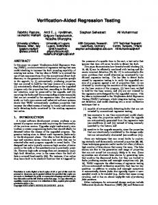
In Section 3 , we had outlined the notations for representation of components and their ports, connectors and their roles, their instances along with attachments. Figure 4 shows these notations representing the architectural elements specified in Wright description of PIS of Figure 3(a). Figure 5 shows the ACDG of the PIS architecture depicted in Figure 3(a). We are interested to compute the dynamic architecture slice on the Pharmacist component for the slicing criterion [S, C4,1 , P24,1 [ξ], patient_health_in f o], where ξ is the event of prescription preparation for the patient. Figure 6 shows the updated ACDG of Figure 5 with the Pharmacist component highlighted for the slicing criterion [S, C4,1 , P24,1 [ξ], patient_health_in f o]. The updated ACDG of Figure 6 is obtained after applying Phase 2 of the SASE algorithm. It depicts the ACDG maintained by the architecture slicer for instance ph (or C4,1 ) of the Pharmacist component. It shows data dependence edges {(C4,1 , −−→ −−→ −−→ −−→ CC 1−34 ), (CC 1−34 ,C3,1 )}, {(C3,1 , CC 1−23 ), (CC 1−23 ,C2,1 )}, {(C2,1 ,
Pathologist : pl
Stop
(a)
Pipe_PL_PH
ta
po
2 P4,1 1 P5,1
Type
Give_Patient_Info
Start
At
m Co
P4,1
C5,1 [pl]
Attachments Port Role
PIS ts
n ne
2 P 3,1 1
C4,1 [ph]
1
prescription
Connector Number
Pipe_Patient_GP
Instances gp : GenPrac sp : SpecialistPrac ph : Pharmacist pl : Pathologist pat : Patient pipe_pat_gp : Pipe_Patient_GP sd : Shared_Data pipe_sp_ph, pipe_sp_pl : Pipe_SP_PHPL pipe_pl_ph : Pipe_PL_PH rpc_gp_ph : Remote_Proc_Call_GP_PH rpc_pat_pl : Remote_Proc_Call_Patient_PL Attachments pat.health_description as pipe_pat_gp.Get_Patient_Info gp.verify as pipe_pat_gp.Give_Patient_Info gp.write as sd.Get_Patient_Info sp.patient_health_info as sd.Give_Patient_Info sp.make_diagnosis as pipe_sp_ph.Get_Patient_Diagnosis ph.diagnosis as pipe_sp_ph.Give_Patient_Diagnosis gp.verify as rpc_gp_ph.Get_Patient_Diagnosis ph.prescription as rpc_gp_ph.Give_Patient_Prescription sp.make_diagnosis as pipe_sp_pl.Get_Patient_Diagnosis pl.medical_test as pipe_sp_pl.Give_Patient_Diagnosis pl.medical_report as pipe_pl_ph.Get_Medical_Test ph.prescription as pipe_pl_ph.Give_Medical_Report pat.health_problem as rpc_pat_pl.Get_Patient_Medical_Test pl.medical_test as rpc_pat_pl.Give_Patient_Medical_Report End Pis
(b)
Figure 3: An Architecture Description of PIS in Wright ADL and its ACFG
5.3
Type
Connectors
Configuration Pis Component GenPrac Port verify = verify ? d verify Port write = begin accept ! d write Computation = verify.verify ? d write.begin computation Component SpecialistPrac Port patient_health_info = data ? d patient_health_info Port make_diagnosis = begin data ! d make_diagnosis Computation = patient_health_info.data ? d make_diagnosis.begin computation Component Pharmacist Port diagnosis = diagnosis ? d diagnosis Port prescription = begin diagnosis ! d prescription Computation = diagnosis.diagnosis ? d prescription.begin computation Component Pathologist Port medical_test = medical_test ? d medical_test Port medical_report = begin medical_test ! d medical_report Computation = medical_test.medical_test ? d medical_report.begin computation Component Patient Port health_description = health_description ? d health_description Port health_problem = begin health_description ! d health_problem Computation = health_description.health_description ? d health_problem.begin computation
PIS Architectural Elements
Illustration of Working of SASE
We explain the working of SASE algorithm by using the example of a Patient Information System (PIS). The PIS helps automate part of the working of a hospital. We first describe the PIS architecture using the symbolic notations defined in Section 3.
72
Pathologist : pl
Connector-4
Pathologist : pl
Connector-4
Connector-7 Connector-5
Connector-7
SpecialistPrac : sp
GenPrac : gp
SpecialistPrac : sp
Pharmacist : ph
Connector-6
Patient : pat
Connector-1
GenPrac : gp
Connector-6
Patient : pat
Connector-1
Connector-5
Pharmacist : ph
Connector-2
Connector-2 Connector-3
Connector-3 Instance of a Component Connector-1 represents Pipe_Patient_GP : pipe_pat_gp Connector-2 represents Shared_Data : sd Connector-3 represents Pipe_SP_PHPL : pipe_sp_ph Connector-4 represents Pipe_SP_PHPL : pipe_sp_pl Connector-5 represents Pipe_PL_PH : pipe_pl_ph Connector-6 represents Remote_Proc_Call_GP_PH : rpc_gp_ph Connector-7 represents Remote_Proc_Call_Patient_PL : rpc_pat_pl
Instance of a Component Connector-1 represents Pipe_Patient_GP : pipe_pat_gp Connector-2 represents Shared_Data : sd Connector-3 represents Pipe_SP_PHPL : pipe_sp_ph Connector-4 represents Pipe_SP_PHPL : pipe_sp_pl Connector-5 represents Pipe_PL_PH : pipe_pl_ph Connector-6 represents Remote_Proc_Call_GP_PH : rpc_gp_ph Connector-7 represents Remote_Proc_Call_Patient_PL : rpc_pat_pl
Instance of a Connector Control Dependence Edge Data Dependence Edge Communication Dependence Edge Event Dependence Edge
Figure 6: Dynamic Architecture Slice for the Slicing Criterion [S, C4,1 , P24,1 [ξ], patient_health_in f o] of the PIS Using the ACDG of Figure 5
Figure 5: An ACDG for the Architecture Description of PIS of Figure 3(a)
T 2. The space complexity of the SASE algorithm is O(n2 ), where n is the number of component instances in the software architecture.
−−→ −−→ CC 1−12 ), (CC 1−12 ,C1,1 )} and event dependence edges (C4,1 ,C3,1 ), (C3,1 ,C2,1 ), (C2,1 , C1,1 ) as service edges. Assuming that the most recent PIS data is available for the component ph (or C4,1 ), we now compute the dynamic architecture slice for the slicing criterion [S, C4,1 , P24,1 [ξ], patient_health_in f o]. At node C4,1 , the outgoing data and event dependence edges are shown as service(thick) edges. Therefore, the dynamic slice for the slicing criterion [S, C4,1 , P24,1 [ξ], patient_health_in f o] is computed at Phase 3 of the −−→ −−→ −−→ SASE algorithm as {C4,1 , CC 1−34 , C3,1 , CC 1−23 , C2,1 , CC 1−12 , C1,1 }. The obtained dynamic slice shows that the instances of component SpecialistPrac(C3,1 ), GenPrac(C2,1 ) and Patient(C1,1 ) affect the event of prescription preparation(ξ) on port P24,1 of C4,1 . More−−→ over, the instances of connector Pipe_SP_PHPL(CC 1−34 ), Shared_ −−→ −−→ Data(CC 1−23 ) and Pipe_Patient_GP(CC 1−12 ) also form a part of the slice on the same event.
5.4
Instance of a Connector Control Dependence Edge Data Dependence Edge Communication Dependence Edge Event Dependence Edge
P. For every node [C x : C x,i ], the SASE algorithm finds dyn_slice(S, C x,i , Pmx,i [ξ]) and stores it in between successive updations of [C x : C x,i ]. To store dyn_slice(S, C x,i , Pmx,i [ξ]) for a node −−→ [C x : C x,i ] linked to a node [Cy : Cy, j ] through a connector CC k−xy , we need at most O(n) space, where n is the number of component instances in the software architecture S. This is because a node [C x : C x,i ] is linked to a single instance of node [Cy : Cy, j ], along with other (n − 1) component instance nodes linked to [C x : C x,i ]. Thus, to store the dyn_slice(S, C x,i , Pmx,i [ξ]), for all the nodes in the software architecture S, we need at most O(n2 ) space. To store the sets DefDataSet(D) and UseDataSet(D) for the data D in the software architecture S, we need at most O(n2 ) space. Therefore, the worst case space complexity of the algorithm is O(n2 ). T 3. The time complexity of SASE algorithm is O(n), where n is the number of component instances in the software architecture.
Correctness and Complexity of SASE
In this section, we prove the correctness of SASE. We also analyze the space and time complexities of SASE. T 1. The SASE algorithm always finds a correct dynamic architecture slice with respect to any given slicing criterion. P. Let us consider a data D with |De f DataS et(D)| ≥ 1, and [C x : C x,i ] be a UseData(D) node. Let ReachFromNode([C x : C x,i ],D) denote the dynamic slice for the slicing criterion [S, C x,i , Pmx,i [ξ], D] for the most recent updation of the node [C x : C x,i ] by the GUE. On successful completion of steps 2.1 and 2.2, the dynamic slice is obtained using all the marked service edges of the updated ACDG and none of the out-of-service edges contribute to the computed dynamic slice. Note that for a DefData(D) node [Cy : Cy, j ] of the form y = f(x1 , ...., xn ), ReachFromNode([Cy : Cy, j ],y) = ReachFromNode([Cy : Cy, j ],x1 ) ∪....∪ ReachFromNode([Cy : Cy, j ],xn ). Therefore, the SASE algorithm always finds correct dynamic architecture slices.
73
P. Let S be a software architecture having n components, and GC be its ACDG. Let C x,i be a component instance of the software architecture S. Consider an state of the node C x,i in an instances scenario of the software architecture S. For updating the run-time information and computing the dynamic architecture slices corresponding to the present state of the node C x,i , the SASE algorithm requires, • At most O(Cn) time is required to fetch the dynamic slices dyn_slice(S, C x,i , Pmx,i [ξ]) and update Dynamic_Slice(S, [C x : C x,i ], Pmx,i [ξ], D) in the step 3(a), where C is the number of component instances and is a constant. Note that step 3(a) is executed conditionally. • At most O(Dn) time is required to update Dynamic_Slice(S, [C x : C x,i ], Pmx,i [ξ], D) for the data D defined for software architecture S in the step 3(b), where D = |De f DataS et(D)| is a constant.
Therefore, the time complexity of the SASE algorithm is linear in the number of component instances in the software architecture.
Table 1: Average run-time requirement and overhead cost of SASE algorithm
In the next section we discuss application for architectural slicing to regression testing.
6.
Sr. No.
Architecture size (# ADL stmt.)
Number of Components
Normal exec. time (in ms)
Average run-time (in ms)
Over head (in ms)
1 2 3 4 5 6 7
250 360 472 557 675 782 894
7 10 12 15 20 23 30
95 118 143 166 191 216 248
144 185 238 296 359 417 483
49 67 95 130 168 201 235
REGRESSION TESTING OF COMPONENT-BASED SYSTEMS
In this section, we present our approach of how regression testing of architectures can be an important application for the architectural slices computed by our slicing algorithm. Software architecture maintainers (or architects) are faced with the task of regression testing of architectures i.e., retesting a architecture after any modification. The goal of regression testing is to ensure that the design level architectural bug fixes, and newly added component functionality do not adversely affect the correctness of the original functionality. Regression testing often involves execution of large architectural ADL specifications on a large number of test cases; thus it can be expensive. Many approaches for regression testing have been proposed [20], but all of them have been based on the program code. Our proposed approach to perform regression testing of software architectures can be applied in the early as well as later phases of software development in support of an maintenance activity. We use the following terminology to apply regression testing to software architectures: The previously working version of an architectural model is referred to as OLD. The architecture obtained by modifying OLD is referred to as NEW. A test suite is a set of test cases applied to the Wright ADL specification, used to achieve a desirable architectural model. Test suit T S OLD is the test suite used to test OLD, and test suite T S NEW is the test suite used to test NEW. Regression testing involves creating test set T S NEW , to validate NEW, and then running NEW on T S NEW . In practice, test suite T S NEW typically contains all of T S OLD plus new tests designed to test the new functionality added to NEW. Running NEW on all these tests is usually too expensive. In case of regression testing of architectures, we ensure that the test cases and the architectural slices from their execution on OLD are available to the architect. Incremental regression testing attempts to exploit this information in two ways. First, if a new component is tested by an existing test case, then the costly construction of a new test case can be avoided. For this reason many techniques attempt to maximize the reuse of tests from T S OLD . Second, it may be asserted that, for a subset of T S OLD , NEW will produce the same output as OLD, then the potentially costly execution of NEW on this subset can be avoided. This occurs, for example, if no changed architectural components in the Wright ADL specification are executed by the test, and the slices do not contain any newly added components and connectors. Our method to incremental regression testing of software architectures is based on the Binkley’s approach [21] of applying program slicing to regression testing. Our approach is modified so as to apply it for regression testing using architectural slicing. Our method has the following steps:
5. Run NEW on T S NEW , the union of the tests produced in Steps (2) and (4). The following comments on our approach makes it clear how the above process works: • Step (3) is performed by running NEW on the tests from Step (2) and marking the components that are executed. The unmarked components are those identified by Step (3). • The size of T S NEW can be minimized. • To re-validate the functionality inherited from OLD (i.e., to ensure that no errors are introduced into NEW), T S OLD can be subset of T S NEW . • If T S OLD is adequate for OLD then T S NEW should be similarly adequate for NEW. • To perform Step (1), a mapping between the components of OLD and NEW is required. We can either develop it prior to testing and take it as an input, or it can be done during testing.
7.
IMPLEMENTATION AND RESULTS
In this section, we present a brief description of a tool that we have developed for regression testing of component-based architectures using our dynamic slicing algorithm. Our tool first computes a slice for an architecture with respect to a given slicing criterion. The current version handles only a subset of Wright ADL constructs. We have named our tool Slicer-based Regression Testing of Wright Architectures (SRTWA). To construct the intermediate representation we have used the compiler writing tools lex and yacc. A Wright ADL architecture description is given as the input to the lex program. The lex program automatically generates the ACDG for an architecture. The semantic analyzer component has been implemented using yacc, the standard tool for LALR(1) parser. During semantic analysis, the Wright architectural description is analyzed token by token to analyze various architectural dependencies. The tokens are first used to construct the ACFG(Architecture Control Flow Graph). Next, using the ACFG the corresponding ACDG(Architecture Component Dependence Graph) is constructed as mentioned in Phase 1(Static Graph Construction) of the SASE algorithm. The architecture description is then automatically instrumented, by the slicer module. We have tested the working of our slicing tool, SRTWA, using several architectures described using Wright ADL and for different slicing criteria. Table 1 summarizes the average run-time requirements and overhead costs of the SASE algorithm. The slices
1. First of all, identify a set of affected components of NEW based on the architectural slices. 2. For architecture S, identify a subset of T S OLD that tests the affected components. 3. Identify untested components of NEW that must be covered by new tests, and those architectural slices of S that contain the untested components. 4. Create new tests for the uncovered components of S.
74
tions. There is no additional space requirement at run-time, as no new nodes are added during the process of slice computation. The time required to compute and display any dynamic slice is O(n), where n is the number of component instances in the architecture. Our intermediate representation captures all the dependencies more clearly, and can correctly resolve event cycles as no component instances are duplicated any time, thereby giving correct dynamic slices. It is therefore clear that our proposed SASE algorithm is more efficient in time and space than the existing architecture slicing algorithms.
Table 2: Memory requirements of SASE algorithm Sr. No.
Architecture size (# ADL stmt.)
# Comp.∗ Instances present
# Conn.+ Instances present
# Attach.− Instances present
Memory reqm. (in KB)
1 2 3 4 5 6 7
250 360 472 557 675 782 894
25 48 57 88 95 110 135
70 115 130 189 210 240 278
95 120 176 223 240 310 358
602 814 990 1225 1450 1580 1898
* Comp. means Components - Attach. means Attachments
9.
+ Conn. means Connector
CONCLUSION
Our architectural slicing algorithm considered Wright ADL. However, it can be generalized to handle architecture specifications given in any other ADL. We first construct an intermediate representation called ACDG for architectures of software systems. Our algorithm is more space and time efficient than related methods. We show how regression testing of architectural specification can be achieved using our slicing approach. We are working to develop a Software Architecture Specification Modifier(SASM) module, so as to have a tool support for evaluating the effect of addition and removal of components at the design level as and when required. This would enable applying our method to systems that can evolve during execution. Many modern systems do provide this capability. Examples of such systems include applications developed using .NET, CORBA, or EJB, in which new components can be loaded and unloaded during execution.
computed in our experiments were checked against manual computation of the slices. This was a validation of the SASE algorithm. The summary of results are provided in Table 1 and 2. From the experimental results, it can be observed that the average run-time requirement increases sublinearly with architecture sizes. Table 2 summarizes the memory requirements of the SASE algorithm. It can be observed that the memory requirement increases as the architecture size increases. This is due to the fact that the number of nodes and edges of the intermediate graph and the number of components increase as the architecture size increases. As the tool SRTWA does not need any trace files to store the execution history, it does not impose any restrictions on the size of the architectures. Also it saves the expensive file I/O operations. Another advantage is that, the marking and unmarking technique used in our approach obviates the necessity to create any new nodes in the repeated use of any architecture components. Thus, the run-time data structure remains bounded even in the presence of repeatative use of components for describing architectures.
10.
REFERENCES
[1] D. Garlan, R. Monroe, and D. Wile, “Acme: an architecture description interchange language,” in CASCON ’97: Proceedings of the 1997 conference of the Centre for Advanced Studies on Collaborative research. IBM Press, 1997, pp. 169–183. [2] D. C. Luckham, J. J. Kenney, L. M. Augustin, J. Vera, D. Bryan, and W. Mann, “Specification and analysis of system architecture using rapide,” IEEE Trans. Softw. Eng., vol. 21, no. 4, pp. 336–355, 1995. [3] M. Shaw, R. DeLine, D. V. Klein, T. L. Ross, D. M. Young, and G. Zelesnik, “Abstractions for software architecture and tools to support them,” Software Engineering, vol. 21, no. 4, pp. 314–335, 1995. [4] R. J. Allen, “A formal approach to software architecture,” Ph.D. dissertation, Carnegie Mellon, School of Computer Science, January 1997, chair-David Garlan. [5] R. Allen and D. Garlan, “A formal basis for architectural connection,” ACM Trans. Softw. Eng. Methodol., vol. 6, no. 3, pp. 213–249, 1997. [6] M. Weiser, “Program slicing,” in ICSE ’81: Proceedings of the 5th international conference on Software engineering. Piscataway, NJ, USA: IEEE Press, 1981, pp. 439–449. [7] J. Zhao, “Applying slicing technique to software architectures,” CoRR, vol. cs.SE/0105008, 2001. [8] ——, “Using dependence analysis to support software architecture understanding,” CoRR, vol. cs.SE/0105009, 2001. [9] B. Li, Y. Zhou, Y. Wang, and J. Mo, “Matrix-based component dependence representation and its applications in software quality assurance,” SIGPLAN Not., vol. 40, no. 11, pp. 29–36, 2005. [10] J. Ferrante, K. J. Ottenstein, and J. D. Warren, “The program
8. COMPARISON WITH RELATED WORK In this section, we compare our work with the existing methods on computing architecture slices. The algorithms proposed by Stafford et. al [14, 15] and Zhao [17, 7, 18] compute a static architecture slice while Kim [19] computes a dynamic architecture slice. The graph representations used in [17, 8, 7, 18] are based on information flow while that in [19, 22, 23] are event-based. These representations do not distinguish among the various dependence relationships arising among components and connectors due to control flow, data change, inter-communication or event completion. Our ACDG represents all these types of dependencies uniquely and therefore can construct more accurate slices. The dynamic architecture slice in [19, 22, 23] is computed by using a trace file, which is used to filter the events based on an event specified in the slicing criterion. The DSAS algorithm of Kim et. al.[19, 22, 23] needs O(N 2 ) space in the worst case and O(N) time to extract architecture slices, where N is the length of event trace. Note that N may be unbounded for architectures containing event cycles and concurrent components. The event cycles can result in incorrect dynamic slices in many cases. The worst case time requirement and space complexity for the architecture slicing algorithms reported by Zhao [17, 8, 7, 18] is quadratic in the number of components, connectors and the attachments. The space complexity of our proposed SASE algorithm is O(n2 ), where n is the number of component instances. Our algorithm does not use event traces, hence does not involve slow file I/O opera-
75
[11]
[12]
[13]
[14]
[15]
[16]
dependence graph and its use in optimization,” ACM Trans. Program. Lang. Syst., vol. 9, no. 3, pp. 319–349, 1987. G. B. Mund, R. Mall, and S. Sarkar, “An efficient dynamic program slicing technique.” Information & Software Technology, vol. 44, no. 2, pp. 123–132, 2002. J. T. Lalchandani and R. Mall, “Computation of dynamic slices for object-oriented concurrent programs.” in APSEC. IEEE Computer Society, 2005, pp. 341–350. G. B. Mund and R. Mall, “An efficient interprocedural dynamic slicing method,” Journal of Systems and Software, vol. 79, no. 6, pp. 791–806, 2006. J. Stafford, D. Richardson, and A. Wolf, “Aladdin: A tool for architecture-level dependence analysis of software systems,” University of Colorado, Dept. of Computer Science, Tech. Rep. CU-CS-858-98, April 1998. J. Stafford, A. Wolf, and M. Caporuscio, “The application of dependence analysis to software architecture descriptions,” in Lecture Notes in Computer Science, vol. 2804, 2003, pp. 52–62. J. Stafford and A. Wolf, “Architecture-level dependence analysis for software systems.” International Journal of Software Engineering and Knowledge Engineering, vol. 11, no. 4, pp. 431–451, 2001.
[17] J. Zhao, “Slicing software architectures,” Information Processing Society of Japan (IPSJ), Tech. Rep. 97-SE-137, November 1997. [18] J. Zhao, H. Yang, L. Xiang, and B. Xu, Architectural Slicing to Support System Evolution. Hershey, PA, USA: Idea Group Publishing, 2005. [19] T. Kim, Y.-T. Song, L. Chung, and D. T. Huynh, “Software architecture analysis: A dynamic slicing approach,” Journal of Computer and Information Science, vol. 1, no. 2, pp. 91–103, 2000. [20] B. Beizer, Software Testing Techniques, 2nd ed. van Nostrand Reinhold, 1990. [21] D. Binkley, “The application of program slicing to regression testing,” Information and Software Technology, vol. 40, no. 11-12, pp. 583–594, 1998. [22] T. Kim, Y.-T. Song, L. Chung, and D. T. Huynh, “Software architecture analysis using dynamic slicing,” in Proceedings of AoM-IAoM 17th International Conference on Computer Science, August 1999. [23] ——, “Dynamic software architecture slicing,” in COMPSAC ’99: 23rd International Computer Software and Applications Conference. Washington, DC, USA: IEEE Computer Society, 1999, pp. 61–66.
76