under the control of standard processors in VME. The host is a VAX 6310 and data are stored on 3480-compatible cartridges. Standard software packages are ...
266
IEEE TRANSACTIONS ON NUCLEAR SCIENCE, VOL. 37, NO. 2, APRIL 1990
REJUVENATION OF A DATA ACQUISITION SYSTEM FOR FIXED TARGET EXPERIMENTS IN A LARGE MULTIUSER SPECTROMETER AT CERN F. Antinori, F. Bourgeois, W. Bozzoli, J.P. Dufey, H. Matthews, Y. Perrin, P. Vande Vyvre, and M.Weymann CERN, Geneva, Switzerland
E.Lamanna, Dipartimento di Fisica University La Sapienza, Roma, Italy
Abstract: this paper describes the new multiuser data acquisition system in operation at the CERN Omega spectrometer since July 1989. Data are buffered from CAMAC, FASTBUS or- VME front-ends during the beam spill whilst processing and event building take place off-spill under the control of standard processors in VME. The host is a VAX 6310 and data are stored on 3480-compatible cartridges. Standard software packages are used throughout and the maximum throughput is about 1 Mbytesh (13 Mbytes of data per spill).
- THE
OMEGADATA ACQUIsrT1oN SYSTEM
Omega, one of the oldest multiuser systems in operation at CERN 111, is a large acceptance detector which is designed for measuring interactions with many particle final states. The trajectories are measured with Silicon Strip Detectors (4000 channels) and multiwire proportional chambers (37000 wires) inside the magnet volume (3 m diameter, 1.5 m height, 1.8 Tesla). Scintillation and Cerenkov hodoscopes are used to trigger in the forward direction, without dead time. Second level triggers involve refined momentum calculations from the hits in the magnet volume together wirh vertex identification by on-line programs. The former data acquisition host, a VAX 11/780, was interfaced to the CAMAC-based R E M S [2] electronics via a fast PDP-11 emulator (MICE [3]) which grouped two or more consecutive events into a super-event to limit the dead-time losses introduced by the slow interrupt response time of the VAX 11/780. REMUS was designed in 1975 as a "read mostly" system for use in large readout systems. It is based on two CAMAC modules : the Read Write Crate Controller, RWCC, and the Read Write Branch Driver, RWBD. All conventional CAMAC block transfer read-out protocols are hardwired in the RWCC and they can be triggered by a broadcast command from the root of the REMUS tree of crates and branches. Though modules in a crate are read serially by the RWCC, the RWBDs read their branches in parallel. Markers and word counts are automatically appended to the data blocks by REMUS thus allowing for the identification of the blocks in the resulting backward pointing tree structure. The RWBD at the root of the tree limits the overall throughput.
2 - HARDWARE ASPECTS OF THE UPGRADE 2.1 -
buffering during
beam
line, from the CERN sps accelerator to The hadron the Omega spectrometer, is being upgraded with a 200 GeV hyperon beam, and a lead beam will be used in heavy ion experiments in the future.
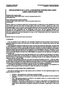
Though event sizes (10 kbytes) are an order of magnitude smaller than those of large collider experiments, throughputs of 10 Mbytes/s are to be expected during the 2.58 sec duration of the beam spill (14.4 sec cycle time). Since most of the front-end CAMAC electronics has no dead-time and it is worth several million dollars, it was decided in mid-1988 to keep it and to overcome the long read-out time of the single rooted REMUS tree by splitting it into 10 independent branches, read out by 4 Mbyte-deep hardwired FASTBUS buffers (STR 350-1 modules from Struck (D)). These spill buffers are triggered in parallel by the final trigger logic and they are read between spills thus achieving the level of derandomization required to maximize the overall throughput. An event directory (8192 word in size) contains pointers to the event blocks as well as flags identifying a few error conditions. Two significant drawbacks of this buffer were identified : the first one was that the STR-350 unit did not calculate the word counts which are normally given by the RWBD, and the second one that there was no absolute tagging of the event slices in each of the 10 spill-buffers, thus leaving place for possible mismatches during off-spill event building. These two problems were solved by the addition of a CAMAC TAGger module in front of each STR-350 as shown in fig. 1 The TAG module inserts a header block whenever it receives a REMUS trigger; it also calculates and inserts the missing word counts. The tag associated with each event is part of the header block and it is, in units of 10 microseconds, the time at which the event occurred since the last Start Of Burst (SOB) 2.2 - The FASTBUSIVSBIVME data acquisition hardware
To accommodate the needs of a variety of users it was also decided to allow for the operation of both VME and FASTBUS equipment at the risk of introducing a large
0018-9499/90/0400-0266$01.000 1990 IEEE
267
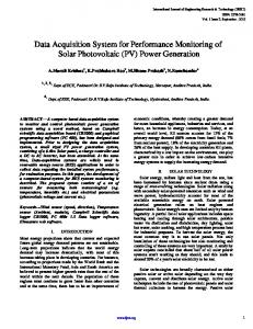
number of different processor types. Though individuals may still use special purpose equipment, most of the data acquisition hardware is based on a single type of VME processor: the FIC 8230, a 68020-based unit with floating point co-processor, 4 Mbytes of dynamic RAM, a 4 channel DMA unit and a VSB port ; a side view of it is shown in fig. 2. The root of the data acquisition system is a VME crate interfaced to the VAX on one side, and to the FASTBUS, VME or CAMAC front-ends on the other (see Figure 1).
CAMAC
BASED DETECTOR eLLCTRONICS 30 1OX
cuxs
R E W S BRANCHES
VME HEW DETECTOR FRONT-ENDS
SPILL
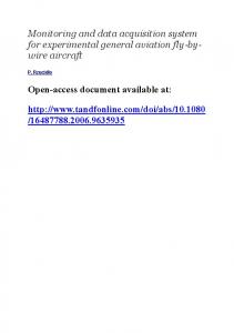
connector of the FIC). The F68B7 is equipped with FASTBUS master port, a FASTBUS slave port, a VSB slave port and a 4 Mbyte memory. This memory is dual ported between the FASTBUS and the VSB side of the module. Since each side has its own 20-Bit address and word counters the memory can be accessed by block transfers simultaneously from both sides. The FASTBUS master port uses asynchronous sequential logic implemented in Programmable Logic Devices. It is a modified version of a design proposed by L. Gustafsson [4]. The FASTBUS master port can autonomously execute simple FASTBUS transactions [5] with the exception of pipelined transfers. It acts as a DMA controller: to start a FASTBUS transaction the VME processor sets up an instruction register and a set of pointers. Once the transfer has started, the processor can poll a ready flag or, alternatively, wait for an interrupt to find out when the transfer has completed. Up to eight F68B7 controllers may be bused on a cable and controlled by a single VME processor. Using the buffer memories, data can be collected from FASTBUS front-end slaves in eight crates in parallel and at a later time be transferred to VME memory for processing. Maximum throughputs are 25 Mbytesh from FASTBUS slave to the F68B7 buffer memory and 6 MBytes/s over the cable connection between F68B7 and VME processor. The buffer memory and most of the control registers of the F68B7 are also accessible via the FASTBUS slave port. This enables another FASTBUS master to transfer data to the VME processor using the FVSBI as a mailbox.
T TO VAX-STATIONS, TERHINAL SERVERS, X-GPX, W E and
GWAC
4
b u r s t intecrupts
CARTRIDGE DRIVE
Figure 1 - In the new Omega data acquisition system, the Fast Intelligent Controller FIC 8230 formats data read from i) FASTBUS through the FVSBI or ii) VME through the VME interconnect port VIC.
Data are transferred between FASTBUS and VME using an FVSBI interface. It is a FASTBUS hardwired master controlled via the VSB port of the VME processor. Physically the FVSBI consists of a single width FASTBUS crate controller unit (the F68B7 shown in fig. 3) and a set of twisted-pair cables and adapter boards which serve to extend the VSB bus over distances of up to 30 m (one of these adapter boards can be seen in fig. 2, plugged into the VME-P2
Figure 2 - Side view of the FIC 8230, the standard processor in use at Omega ; the VSB to twisted-pair level shifter board can be seen on the VME-P2 connector.
268
the front-end spill buffers, data transfers are asynchronous with respect to the beam spill and all 14.4 s of the SPS's cycle time can be used for data transfer to the host, thus giving a theoretical upper limit of 22 Mbytes of data per spill. The VAX is equipped with 1.2 Gbytes of disk storage, 32 Mbytes of RAM and a 6250 bpi tape drive. The data is recorded on IBM 3480-compatible cartridge tapes (TA90 cartridge drives from DEC). 2.4 - Control and Monitoring Trigger and data acquisition parameters are set via CAMAC at the beginning of a run or, else, off-spill after Occurrence of an End Of Burst (EOB) interrupt. Off-spill, the STR-350 buffers are in the se-called "transparent" mode and the VME processor has full control of the REMUS tree via the CAMAC Branch Driver CBD 8210 (from CES, Geneva, (C". Ethernet is used throughout for downloading the processors. 3 - THE DATA ACQUISITION SOFTWARE 3.1 - Thefront-end software The front-end system has to perform the following tasks:
- Transfer the data from the FASTBUS spill buffers to the VME processor's memory, and perform the event building. Transfer the data to the host computer, over the HVR DRB32 link. - Perform all the CAMAC operations that will configure the system at start of run and when switching between spill and inter-spill mode. - Communicate various informations to the host on the behaviour of the data acquisition; execute all actions required by the host-based run control.
-
Figure 3 - Side view of the F68B7 master which interfaces FASTBUS to VSB.
Multi-crate VME systems have not yet been implemented. They might use the VIC bus (from CES, Geneva, (CH)) as shown in fig. 1. 2.3 - From VME to the Host In the case of the Omega data acquisition system, the FVSBI is used to reassemble off-spill the event slices stored in each Spill Buffer (STR-350) into one complete event which is then transferred to the buffer manager of the SPIDER [6] (Simple Portable Interactive Data Acquisition Environment) data acquisition system in the VME processor. The capability of the FVSBI to interrupt the VME processor after completion of a FASTBUS operation has been used to emulate an interrupt driven environment for SPIDER in the absence of real event triggers during the inter-burst period. The HVR 8217 from CES, Geneva (CH) interfaces the VME root crate to the VAX 6310 host computer. This interface is Master or Slave on its VME port, Master on its VSB port and connects to a DRB32 inpudouput port on the VAX BI bus. The data transfer rate between VME and the VAX is greater than 1.5 Mbytes/sec. With the exception of
It should be noted here that the front-end processor does not see the actual event interrupts, but only the start and end of spill signals. Therefore any CAMAC functions that need to be executed at that level are stored at start of run in the tag modules. The implementation of this part uses the VALET-Plus system [6] which provides a full, VME based, environment for the implementation of data acquisition systems. The processor runs the MONICA [7] mono-tasking operating system with the language PILS (Portable Interactive Language System) [81 for the development of applications. This system is complemented with a set of library modules to perform CAMAC, VME and FASTBUS operations. Valet provides file server, remote login and communication facilities using Ethernet as a link with the host computer. The implementation of these facilities relies to a large extent on the RPC (Remote Procedure Call) concept [9].
269
The data acquisition program in the front end is based on SPIDER [lo], a standard package running in Valet. It has been complemented with routines that perform tasks specific to the OMEGA system. In particular the module that transfers data from the spill buffers over the FASTBUS-VME link reads the event directories from each spill buffer first, then it generates FASTBUS commands that will transfer the event slices into the memory of the FASTBUS part of the FVSBI in such a way as to perform the event building remotely and without the need of a FASTBUS processor; the full event is then transferred to the Rc's memory. The data transfer to the host computer is controlled by SPIDER which interrupts the host resident event producer. The high level protocol is CATS [ 113. The DRB32 driver on the VAX is a product developed jointly by CERN and DEC. 3.2 - The host data acquisition software The architecture of the data acquisition system controlling the flow of data through the host.consists of: an event buffer together with the software to control the flow of data, possibly to modify the contents of the events and to distribute them to the various consumer tasks, according to some selection criteria; a "producer" task that ensures the link with the front end data acquisition. It services the interrupts initiated by SPIDER, controls the transfer of data and loads it into the event buffer; a "consumer" task that takes the events from the event buffer and writes them to tape and an additional module, active at start of run, that has the task of injecting special records into the data stream (e.g. calibration data that have to be written to tape). These modules include a control part that is able to receive and execute commands, and that may give information about their current status; occasionnally they will have to signal a failure or the impossibility to execute the requested command. One additional module with such control capabilities has been realised to download the software into the front-end processor and to convey to it all the run control commands.
A set of visual displays provide the users with continuously updated information on the run conditions, the data flows and the active tasks. This includes also display of all types of messages issued by those tasks. The implementation of this system was based entirely on the MODEL scheme developed by the CERN-DD division [W. The event buffer is built with the Model Buffer Manager (MBM) [ W . The event producer and the SPIDER controller are provided by the Model SPIDER producer package (MSP) [141 and rely on the CATS transport protocol and on the RPC system. The tape writing module is derived from the Model Recorder System (MRS) [15]; it has been adapted to the TA90 cartridge unit and uses multiple buffers in order to take advantage of the full bandwidth of the tape drive. The run control has been built using the State Manager (SM) system that allows states and transitions of a finite state machine to be defined. The communication with the control modules is based on the Occurency Signalling Package (OSP) [16]. The interactive display, showing the status of the components of the data acquisition system as well as their state transitions, and allowing interaction with individual modules has been developed by the CERN-LEP DELPHI Collaboration. The control of the monitoring programs is ensured by the Model Process Control (MPC) [ 171. The monitoring programs themselves are linked with the Model Process Frame library (MPF) [18] that provides the connections with the event data stream and with MPC. All the packages described above use the Model Human Interface [19] together with the EMU error message software [20] to realise the operator communication. The collaboration between the DD group, that provides the Model environment, and the OMEGA team has allowed us to improve the standard products and to develop a set of modules that constitute a complete data acquisition system that can be installed in other experiments, whereas the Model concept in itself, being a set of tools, does not provide such a system.
A Run Control module, that provides operator interaction Finally it is worth mentioning that particular attention has facilities, contains all the rules for sequencing and been devoted to the conversion of the monitoring programs synchronizing the commands to all of those modules. Its task from the old system to the new one. A set of tools and is to control the global run functions, such as START, interfaces have been prepared from the very beginning of the STOP, PAUSE. Operator access to the individual modules is upgrade project and have proved to be very powerful: a also provided in order to define the various configuration monitoring program that followed closely the rules of the parameters and to handle abnormal conditions. previous system can be converted in about one hour. A high level language, ORACLE [21], developed about 10 years ago, The monitoring programs are controlled by a separate that generates monitoring programs, has been converted as module that allows them to be detached from the terminal well, and the applications that were based on it could be from which they were initiated and, conversely, to be retransferred to the new system without any change. attached to a(nother) terminal for communication.
270
4 - PERFORMANCE OF THE OVERALL SYSTEM
The maximum transfer rates at the various levels of the hardware are given below: - REMUS to
Spill-Buffer: 1.4 Mbyte/s ; FASTBUS Slave to F68B7: 20 Mbyte/s ; - F68B7 memory to FIC processor: 2.5 Mbyte/s ; - VME to VAX: 1.6 Mbyte/s; - VAX to cartridge drive: 2 Mbyte/s.
[5] U.S NIM Committee, FASTBUS Standard Routines, CERN DD/OC (March 1987). [6] R. Bagnara et al., The VALET-Plus embedded in large Physics Experiments, VMEbus in Research, North Holland (1988).
-
The overall speed of the system, 7 Mbytes per 2.58 second spill, is limited by the buffer handling algorithms currently used in the processor and the VAX. Systematic studies of the throughput as a function of the event size allowed us to conceive improvements which will certainly double the current speed. In the future, higher throughputs can be expected hom a mUltiprOCeSSOr architecture in the VME Crate at the root Of the system.
5 - CONCLUSION The choice of standard, commercially available electronics and of general purpose software packages has allowed us to implement a new data acquisition system with relatively modest resources: 300 K$, including a host computer and the recording system, and 2.5 man-years of effort. The new system has a throughput up to 10 times greater than the previous system. In the near future, the system will handle multiprocessor configurations in VME. 6 - ACKNOWLEDGEMENTS
The authors are grateful for the encouragement and support of Drs P. Darriulat, H. Wenninger, W. Beusch and B. French. We must also acknowledge stimulating discussions with members of the WA89 collaboration who contributed to the design and purchase of the spill-buffers. We finally thank the members of the CERN DD-OC group for their continuous support at all stages of the project. 7 - REFERENCES [l] W. Beusch, Omega Prime, a project of improving the Omega particle detector system", CERN SPSC 77-70, (1977). . . [21 F. Bourgeois, Proposal for a large scale data acquisition system using CAMAC, CERN/EP 75-4 (1975). 131 J. Anthonioz-Blanc et al., MICE, a fast user programmable emulator of the PDP-11, CERNDD/80-14 (1980). [4] L. Gustafsson, "A VME to FASTBUS interface using a finite state machine Coprocessor" , Computer Standards & Interfaces Nr8, (1988/89) 91-101
[7l MONICA, CERN Data Handling Division.
[8] R.D. Russell, L. Tremblet and D.O. Williams, PILS reference manual, CERN DD (31 March 1987). [93 T. Berners-Lee, Programming distributed systems Remote Procedure Call, VMEbus in Research, North Holland (1988). [lo] SPIDER User's Manual, OC-Group CERN Data Handling Division. [11] G. ~ ~The CATS i Transport ~ Service ~ Calling ~ Sequence, CERN/DD/CS/CATS/Rl. [12] C. Boissat et al., MODEL: a software suite for data acquisition, Oxford Conference 1989, R. Devenish, T.Daniels eds., North Holland (to be published) or CERN/DD/89/26. [13] C. Boissat and P. Vande Vyvre, "The MODEL Buffer Manager User's Guide", CERNDOC: [MODEL DATA-ACQUISITION MBM-USER] [14] W. Bozzoli and E. Lamanna, Model Spider integration Programs, CERNDOC: [MODEL DATAACQUISITION MSP-USER], being written. [15] P. Vande Vyvre, The MODEL Recording System User's
Guide", CERNDOC: [MODEL ACQUISITION h4RS-USER] .
DATA-
[16] R. Jones, OSP User's Guide, CERNDOC: [MODEL UTILITIES OSP]. [17] J.P. Matheys, MODEL Process Control User Manual, CERNDOC: [MODEL PROCESS-CONTROL MPC-USER]. [18] J.P. Matheys, Monitoring Process Frame User Manual", CERNDOC: [MODEL DATA-ACQUISITION MPF-USER] . [19] C. Boissat, R. Jones and G. Mornacchi, Model Human Interface User's Guide, CERNDOC: [MODEL HUMAN_LNTERFACE MHI-USER] [20] P. Burkimsher, The EMU User Guide, CERNDOC: [MODEL ERROR-MESSAGE-UTIL EMU]. [21] J.P. Dufey, ORAVAX on-line monitoring package, DD/EE/81-3 (September 1983).
,