ADVANCES IN MANUFACTURING SCIENCE AND TECHNOLOGY
Vol. 36, No. 1, 2012
RELATION BETWEEN KINEMATIC STRAIGHTNESS ERRORS AND ANGULAR ERRORS OF MACHINE TOOL
Paweł Majda
Summary
The article presents the results of simulation studies aimed at verifying the usefulness of the concept of calculating kinematic straightness errors from angular errors. Based on the calculations of a flexible machine tool, no relationship was found between the two types of errors. This clearly shows that straightness errors and angular errors of machine tools should be treated as independent of each other. Keywords: kinematic errors, geometrical errors, machine tool Relacja pomiędzy kinematycznymi błędami prostoliniowości i błędami kątowymi maszyn technologicznych Streszczenie
W artykule przedstawiono wyniki badań symulacyjnych, celem zweryfikowania przydatności opracowanej koncepcji przeliczania charakterystyk błędów kinematycznych prostoliniowości na podstawie charakterystyki błędów kątowych. Analiza wyników obliczeń odkształcalnego stołu obrabiarki nie potwierdziła ścisłej zaleŜności pomiędzy tymi błędami. Jest to podstawą do stwierdzenia konieczności traktowania błędów prostoliniowości i błędów kątowych obrabiarek jako niezaleŜnych. Słowa kluczowe: błędy kinematyczne, błędy geometryczne, obrabiarki
1. Introduction Issues of the accuracy of machine tools, being extremely important from a practical point of view, include the detection and determination of the types and sources of errors affecting accuracy, as well as methods for their compensation. Problems with the accuracy of shapes, dimensions and geometric structure of workpiece surfaces are caused by a number of factors associated with the mechanical states and behaviors of the machine tool-workpiece-chucktool. They depend on many factors such as guideway geometric errors [1], thermal errors, errors associated with deformations: guideway components [2], cutting tools [3], static [4] and dynamic [5] properties of the carrier machine. However, accuracy depends mostly on the machine tool, its design features, quality of production and assembly, physical phenomena generated during its Address: Paweł MAJDA, Ph.D. Eng., West Pomeranian University of Technology, Al. Piastów 19, 70-310 Szczecin, e-mail:
[email protected]
48
P. Majda
work, variability of working conditions of the control system components, and finally, external influences. This paper concerns the table of a typical mid-sized milling machine with guideways. In order to examine the relationship between the kinematic straightness errors and angular errors of this table, guideways were ascribed geometric errors. The focus on the effect of geometric errors of guides on the resulting straight-line geometric accuracy resulted from the systematic character of these errors. The consequence of this is that one can effectively compensate for this effect using numerical control of machine tools.
2. Machine tool volumetric error modeling Geometric error modeling of serial kinematic structures (such as a machine tool or coordinate-measuring machines) is carried out mostly based on the assumption of rigid body kinematics. The modeling results in analytical dependencies with which one can calculate the values of individual components (for each axis) of the volumetric error (VE). Determination of the VE map for a three-axis machine tool requires the knowledge of the 21 components of axis errors. Derivation of equations is done mostly using homogeneous transformation matrixes (HTM). Under these assumptions, Ehmann et al. [6] presented a method for building a general error model to include multi-axis structures with any kinematic configuration. Okafor et al. [1] presented a derivation of HTM matrixes that included machine tool thermal errors. Ahn et al. [7] supplemented the VE model with a component containing axis backlash. Raksiri et al. [8] presented a synthesis of machine tool geometric errors with tool deformation errors. They used neural networks to analyze these two sources of error, the neural network being taught on the basis of the measurements of 21 kinematic errors and VE modeling using HTM. Chen [9] and others proposed measuring displacement along 15 lines (variously oriented in the workspace) and using the results of this measurement to determine the 21 components of kinematic errors. Another work [10] developed a method to determine 21 machine errors based on the results of diagonal measurements in workspace. Lei and Sung [11] proposed modifications to the position of nodal points for the tool path described by NURBS curves. To determine the compensation value for the position of nodal points they also used HTM. Based on a literature review it can be concluded that in most studies on VE determination, despite the changing forms of the equations, the methods of derivation and the use of different computational techniques (regression, artificial intelligence, etc.), the concept of rigid body kinematics is still commonly used. Even the latest measurement systems for the determination of machine tool errors and coordinate measuring machines using tracking interferometers are being equipped with software based on geometric
Relation between kinematic straightness errors ...
49
transformations of rigid body displacements. An example of this approach can be found in the algorithms used by the ETALON company [12] and developed under the supervision of Schwenke [13, 14]. Given that the assumption of the perfect rigidity of machine components is allowed as it does not result in significant errors in modeling VE maps, one can substantially simplify measurement procedures. The possibility of calculating straightness errors from the relevant characteristics of angular errors is particularly attractive in this regard. Is this kind of simplification acceptable? This issue is discussed in a further part of this paper.
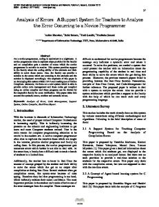
3. Relation between kinematic straightness errors and angular errors Various authors have different approaches to the characteristics of machine tool kinematic errors. Some argue that allowing for the correlation between translational and rotational errors one can express straightness errors using integrals of functions of the respective angular errors [15, 16] or (reversely) can calculate rotational errors by differentiating straightness errors [17]. In contrast, other researchers treat them as mutually independent [1, 7, 8, 18, 19]. The possibility of converting one kinematic error into another error is very attractive due to the shorter time of measurement. By measuring six characteristics of rotation errors for a three-axis machine tool, one can convert them into six consecutive characteristics of translation errors. Equations taking into account the aforementioned correlations and matrix of geometric deviations is shown in Fig. 1. The concept of converting the rotation deviation into straightness deviation is well known [20]. The authors of the publication [21] have given a detailed analysis of this concept in relation to simplifications used to convert rotation errors in straightness errors. They experimentally verified analytical projections for a two-dimensional model (considering the problem in the vertical plane) and showed that the accuracy of the calculation of straightness deviation integrals from rotation deviation depends on the ratio between the length of the guide (table, carriage) and the wavelength deviation in the guide (guide rail) understood as straightness deviation. At some ratios of these lengths, conversion of one deviation into another can lead to significant errors both in terms of value and even sign. The authors conducted their analytical considerations and experimental studies in the convention of perfectly rigid block kinematics. In addition, they found that if the inequality of the guide wavelength deviation is much greater than the length of the guide, then using the rotation deviation integral as a respective straightness deviation results in a negligibly small error. Hence, according to the authors in this case the conversion of kinematic error deviations was justified.
50
P. Majda
Fig. 1. Expression of straightness error by the integrals of corresponding rotation errors
Presented in [22], the method of geometric guideway error modeling enables the verification of the correctness of the assumption about the conversion of kinematic angular errors into straightness errors. It should be emphasized that the proposed method is devoid of far-reaching simplifications such as the restriction to a two-dimensional case, and ignoring strain/formability. Below are the results of a computing session aimed at determining whether converting straightness deviations from rotation deviation integrals result in significant errors. Wavelength deviation in this case is much greater than the length of the guide in question. The calculations were performed using the finite element method - FEM. Modeling concerned a typical medium size machine tool table. The computational simulations assumed a priori function describing geometrical errors in the local coordinates of guide rails using the equation: x x δ ⋅δ + ⋅ 1000 1000 2 2
geometrical error
=
(1)
where: δ = 0.05 mm, x in mm – current position of the table. In the discussed approach, the machine table is subjected to kinematic excitation resulting from guide rail geometric errors. We analyzed a variant in
Relation between kinematic straightness errors ...
51
which the first rail has a geometric error in the vertical plane and the second has a geometric error in the horizontal plane. The results of the computational session for straightness errors (vertical straightness and horizontal straightness) for the table are shown in Fig. 2 and Fig. 3. The initial value (zero) of the table position relative to the guides was adopted as the geometrical center of the guideway. On the X-axis is the current position of the table, and on the Y-axis is the value of the kinematic error. In the Figures, there are schematic drawings showing the location of the rail geometric error. Each of the characteristics of the kinematic error were made for five control points (P1÷P5) on the surface of the table - the four corners and the middle of the table.
Fig. 2. Comparison of computational characteristics of vertical straightness error for a machine tool table: a) direct result of modeling, b) indirect result – integration of angular error (pitch error)
Fig. 3. Comparison of computational characteristics of horizontal straightness error for a machine tool table: a) direct result of modeling, b) indirect result – integration of angular error (yaw error)
Figure 2b and 3b present characteristics of the straightness error calculated as the result of integrating the relevant characteristics of the angular error (also determined using FEM). The integral of the pitch error corresponds to the vertical straightness error, while the integral of the yaw error corresponds to the
52
P. Majda
horizontal straightness errror. If there exists a correct relationship between the straightness errors and angular errors, then the characteristics in Fig. 2b and 3b should be the same as the corresponding characteristics in Fig. 2a and 3a.
Conclusions In this paper, small differences in the characteristics of straightness error obtained directly and from conversion from corresponding rotation errors were obtained only in the central point of the table (Fig. 2 and Fig. 3). At any other point on the machine table, the conversion lead to significant differences in the conversion of straightness deviations from respective angular deviations. In general, the determination of the straightness error based on the rotation error is subject to the influence of undetermined effects of strain/formability of the table under kinematic excitations originating from geometric errors. In the analyzed example, no close relationship between kinematic straightness errors and angular errors were found. If no such relationship has been confirmed in the idealized model (without measurement uncertainty), the use of similar simplifications in the analysis of a real object are unacceptable. The work was financed from the resources for National Science Centre as a research project no. References [1] A.C. OKAFOR, M.Y. ERTEKIN: Derivation of machine tool error models and error compensation procedure for three axes vertical machining center using rigid body kinematics. Inter. Journal of Machine Tools & Manufacture, 40(2000), 11991213. [2] P. GRUDZIŃSKI: An analysis of normal contact deformations in the basic model of a roller guideway of machine tool. Advances in Manufacturing Science and Technology, 33(2009)3. [3] A. KAWALEC, M. MAGDZIAK: Deformations of selected milling cutters while milling TI6AI4V alloy on a CNC machine tool, experimental tests and FEM modeling. Advances in Manufacturing Science and Technology, 35(2011)4. [4] D. JASTRZĘBSKI: Modelling of static properties of load-carrying system of machines tools using hybrid finite element method. Advances in Manufacturing Science and Technology, 32(2008)1. [5] B. POWAŁKA: Roundness error prediction in valve seat machining based on cutting force model and machine tool system dynamics. Advances in Manufacturing Science and Technology, 32(2008)1. [6] K. F. EHMANN, B. T. WU, M. F. DEVRIES: A generalized geometric error model for multi-axis machines. Annals of CIRP, 36(1987)1, 253-256. [7] K. G. AHN, D. WOO CHO: Proposition for a volumetric error model considering backlash in machine tools. Inter. Journal Adv. Manuf. Technol., 15(1999), 554-561.
Relation between kinematic straightness errors ...
53
[8] C. RAKSIRI, M. PARNICHKUN: Geometric and force errors compensation in a 3axis CNC milling machine. Inter. Journal of Machine Tools & Manufacture, 44(2004), 1283-1291. [9] G. CHEN, J. YUAN, J. NI: A displacement measurement approach for machine geometric assessment. Inter. Journal of Machine Tools & Manufacture, 41(2001), 149-161. [10] J.S. CHEN, T.W. KOU, S.H. CHIOU: Geometric error calibration of multi-axis machines using an auto-alignment laser interferometer. Journal of the International Societies for Precision Engineering and Nanotechnology, 23(1999). [11] W.T. LEI, M.P. SUNG: NURBS-based fast geometric error compensation for CNC machine tools. Inter. Journal of Machine Tools & Manufacture, 48(2008), 307-319. [12] http://etalon-ag.com/ , 2012.01.10. [13] H. SCHWENKE, M. FRANKE, HANNAFORD J.: Error mapping of CMMs and machine tools by a single tracking interferometer. CIRP Annals – Manufacturing Technology, 54(2005), 475-478. [14] H. SCHWENKE, W. KNAPP, H. HAITJEMA, A. WECKENMANN, R. SCHMITT, F. DELBRESSINE: Geometric error measurement and compensation of machines – An update. CIRP Annals – Manufacturing Technology, 57(2008), 660-675. [15] F. BIRAL, P. BOSETTI: On-line Measurement and Compensation of Geometrical Errors for Cartesian Numerical Control Machines. Proc. 9th IEEE International Workshop 2006, 120-125. [16] A.K. SRIVASTAVA, S.C. VELDHUIS, M.A. ELBESTAWIT: Modelling Geometric and thermal errors in a five-axis CNC machine tool. Inter. Journal of Machine Tools & Manufacture, 35(1994)9, 1321-1337. [17] H.J. PAHK, J.S. KIM, J. MOON: A new technique for volumetric error assessment of CNC machine tools incorporating ball bar measurement and 3d volumetric error modelint. Inter. Journal of Machine Tools & Manufacture, 37(1997)1, 1583-1596. [18] K.G. AHN, B.K. MIN, Z.J. PASEK: Modeling and compensation of geometric errors in simultaneous cutting using a multi-spindle machine tool. Inter. Journal Adv. Manuf. Technol, 29(2006), 929–939. [19] A.C. OKAFOR, Y.M. ERTEKIN: Vertical machining center accuracy characterization using laser interferometer. Part 1. Linear positional errors. Journal of Materials Processing Technology, 105(2000), 394-406. [20] PN-ISO 230-1: Przepisy badania obrabiarek, Dokładność geometryczna obrabiarek pracujących bez obciąŜenia lub w warunkach obróbki wykańczającej. [21] T.O. EKINCI, J. R. R. MAYER: Relationships between straightness and angular kinematic errors in machines. Inter. Journal of Machine Tools & Manufacture, 47(2007), 1997-2004. [22] P. MAJDA, G. SZWENGIER: Modeling and experimental research of machine tool geometric errors. Proc. XIV National and V International Scientific and Technical Conference – Metrology in Production Engineering, Warszawa 2011, 208-213. Received in October 2011