In the present world of software development, software ... terprise software applications. Business ..... database design, Addison-Wesley, Boston, MA, USA, 2001.
Relational Database Operations Modeling with UML Shuxin Yin Indrakshi Ray Department of Computer Science Colorado State University yin, iray @cs.colostate.edu �
Abstract Many existing software applications involve complex application layer implemented in OO programming languages and at the same time use relational database systems as back-end data store. Modeling the whole system in a consistent manner will help developers and end users better understand the application. Application layer and database layer sometimes are tightly coupled together in some legacy systems; however, most people use UML and ER modeling to model these two layers respectively, which creates lots of inconsistencies. Database operations can’t be properly modeled using ER modeling. In this work we present an extension to UML Data Modeling Profile and use concrete examples to illustrate how to model relational database operations using UML. Atomic database operations are modeled based on our framework and are used as building blocks to model more complex database operations.
1. Introduction In the present world of software development, software applications are becoming more and more complex. Most enterprise software systems include presentation and application layer which are implemented in object-oriented programming languages. A lot of these applications are used to process huge amount of data which is stored in database systems. In fact, many legacy systems are still using relational database management system (RDBMS). Because of the dominant position of RDBMS, this hybrid model is still being used in many newly developed applications. The Unified Modeling Language (UML) has become widely used in object-oriented system modeling such as J2EE and .NET. Yet Entity-Relationship (ER) model still dominates relational database application modeling. These two techniques are not fully compatible and confusions among developers and end-users while using these two techniques at the same time affect overall system development and maintenance. Modeling the whole application using one standard
will greatly enhance program understandability and facilitate communication between application development team and database team. Relational database systems play an important role in enterprise software applications. Business information is processed and manipulated at database level before being used by applications. These database operations implemented in packages, stored procedures, triggers and functions can be very complex. Modeling these operations improves understandability, reusability and maintenance of the database system. ER modeling only captures the static schema but can’t model dynamic operations. Current UML modeling standard doesn’t fully address this program as well. There are many kinds of database systems; we will limit our discussion to relational databases in this paper. With the development of programming languages and software engineering techniques, software development has evolved from simple monolithic applications into powerful systems which could contain millions of lines of code. No matter what programming languages we use, there are still plenty of cases where application code and database code are coupled together. We need to reverse engineer these systems for various reasons; modeling this kind of hybrid system properly will improve the understandability of the whole system and facilitate future system enhancement. Most enterprise level applications involve end users, business analysts, application development team and database team; modeling the whole system using one standard will make communication among team members much easier. Collaboration and cooperation has always been a key aspect of overall system success. The UML gives us the ability to model, in a single language, the business, application, database, and architecture of the system. By having one single language, everybody involved can communicate their thoughts, ideas, and requirements [11]. UML Data Modeling Profile [8][16] was proposed by Rational Software from IBM. The use of Data Modeling Profile for the UML has helped open the UML to database design [11]. UML can be used to model rational database
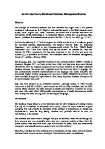
Pollutant PK PollutantID:INT 1 PollutantNae:VARCHAR(50) CASNumber:VARCHAR(50) PK_Pollutant()
Concentration 0..* PK ConcentrationID:INT SiteID:INT PollutantID:INT ObservationDate:DATETIME ConcentrationValue:FLOAT FK_Concentration3() FK_Concentration2() PK_Concentration() 0..* 1
SP_1 ReportByPollutant(PollutantID:INT):Void ReportBySite(SiteID:INT):Void
Site PK SiteID:INT SiteName:VARCHAR(50) Address:VARCHAR(50) City:VARCHAR(50) State:VARCHAR(2) Zip:CHAR(5) Latitude:FLOAT Longitude:FLOAT PK_Site()
Figure 1. Air toxics data archive UML data model
schema and it is more expressive than ER modeling. Yet the current UML database modeling techniques mainly focus on static schema modeling. Dynamic database operations are modeled in an ad hoc manner. The major contribution of this work is to identify the weakness of UML Data Modeling Profile, i.e., lack of abilities to model operations. We will propose a framework on how to model operations at database level. SQL is essentially built upon relational theory. We will show how to model atomic operations in SQL Data Manipulation Language (DML) based on relational algebra and set theory. SQL is a declarative language; it allows us to express what we want without going into the details about where it’s located or how to get it [7]. We are not trying to model the internal execution details such as parsing SQL statement, validating the statement, optimizing the statement, generating an execution plan and executing the execution plan. All these details should not be exposed to application developers. On the other hand, modeling database operations at SQL statement level makes it easy for end users to understand the database operations. The rest of this paper is organized as follows. We describe how to model atomic SQL DML constructs in Section 2. We will use an example to show how to model complex database operations in Section 3. Finally we present our conclusions in Section 4.
2. Atomic DML Operations Modeling We use the example of an Air Toxics Data Archive to explain our ideas. Figure 1 is an example of UML data model generated by Rational Rose. There are two stored proce-
dures in this example indicated by the stereotype ¡¡SP Container¿¿. Using Rational Rose, we can model stored procedures using activity diagram and state machine diagram. Actions and states will be represented in English which is ambiguous. Moreover, this representation will not capture the relationships between the tables, SQL DML and actions in the activity diagram.
2.1. Relational Theory Relational database theory is based on Relational Model [4] and set theory. According to Relational Model, relational tables are sets. The rows of the tables can be considered as elements of the set. Operations on sets can also be performed on relational tables. The eight relational operations are union, difference, intersection, product, projection, selection, join and division. SQL translates the relational theory into practice. SQL is a language that is a loose implementation of relational theory, and has been further modified in its actual implementation by the RDBMS software that uses it [7]. We will use the operations defined in relational theory to model SQL DML operations.
2.2. SQL Data Manipulation Language Essentially all database operations are implemented using atomic SQL data manipulation language constructs such as INSERT, UPDATE, DELETE, and SELECT. In this section we will model standard SQL data manipulation language constructs and use them as building block to model more complex operations in the next section. We all know that there is no object in RDBMS and operations are separated from tables. On the other hand, we can think of a row as an anonymous object of a class as defined by the table. There are four predefined operations upon this object which are INSERT, UPDATE, DELETE and SELECT.
2.3. Insert Operation Modeling INSERT statement is the simplest operation in DML. Here is an example: INSERT INTO Pollutant (PollutantID, PollutantName, CASNumber) VALUES (1, ‘Ethylbenzene’, ‘100414’) At a higher level, we can model this operation using use case diagram as shown in Figure 2. An insert operation
:Pollutant
System
UPDATE SELECTION:PollutantID=2
Add a new Pollutant SET:CASNumber=’103333’ Actor
Figure 5. Update operation sequence diagram
Figure 2. Insert operation use case diagram
1.1:SELECTION:PollutantID=2 :Pollutant
1.2:SET CASNumber=’103333’
1:UPDATE :Pollutant
INSERT
:Pollutant
Figure 6. Update operation communication diagram
SET: PollutantID = 1, PollutantName=’Ethylbenzene’, CASNumber=’100414’
2.4. Update Operation Modeling Figure 3. Insert operation sequence diagram
can also be modeled using sequence diagram, communication diagram, activity diagram, interaction overview diagram and state machine diagram. Figure 3 is a sequence diagram example. An anonymous stereotyped object is used to represent a data row in Pollutant table. INSERT operation is considered as a predefined operation of Pollutant table. We encapsulate the whole statement into a named framed part,which is a newly added feature in UML2.0[18], called INSERT. SET is considered as an atomic operation in our model which assigns value to a single row or a data set. The SET operation is treated as a synchronous operation here. A communication diagram is shown in Figure 4. Again we use an anonymous stereotyped object to represent the Pollutant table. The same operation can be represented using state machine diagram and activity diagram as well.
1:INSERT :Pollutant
Figure 4. Insert operation communication diagram
UPDATE operation can be more complex than INSERT operation since it can include optional WHERE clause. In such case, an update operation can be decomposed into the following steps: 1) Selection: find the rows to be updated based on specific conditions first; 2) Set: update the old value with the new value. Here is an example: UPDATE Pollutant SET CASNumber = ‘103333’ WHERE PollutantID = 2 In this example, we use a framed part UPDATE to represent the update statement as a whole and use SELECTION and SET as individual steps to implement the statement. SELECTION has the same semantic meaning as defined in relational theory. Again, SET is an atomic operation which updates a data set. An equivalent communication diagram is shown in Figure 6. Multiple columns can be modified in one statement; in this case, we can separate these expressions using comma, which is the same as SQL. The label become means the Pollutant data set is changed. �
�
2.5. Delete Operation Modeling Delete operation is similar to update operation except that the rows are removed from the table and DESTROY operation is executed upon the table. A typical delete statement is listed below and its sequence diagram and communication diagram are shown in Figure 7 and Figure 8. DELETE FROM Pollutant WHERE PollutantID = 11
:Pollutant
:Pollutant SELECT
DELETE
GROUP BY: SiteID, PollutantID HAVING SiteID >=1
SELECTION:PollutantID=11
PROJECTION:SiteID, PollutantID AVG(ConcentrationValue) DESTROY
ORDER BY: AVG(Concentration)
Figure 7. Delete operation sequence diagram
Figure 9. Sequence diagram for select statement with GROUP BY
1.1:SELECTION:PollutantID=11 1:DELETE :Pollutant
1.2:DESTROY
:Pollutant
C:Concentration SELECT
Figure 8. Delete operaton communication diagram
Here we use DESTROY to replace SET. DESTROY is considered as another predefined operation upon a table which means deleting data set based upon SELECTION result.
P:Pollutant
JOIN:C.PollutantID=P.PollutantID SELECTION:P.PollutantName, C.SiteID, C.ObservationDate, C.ConcentrationValue
Figure 10. Sequence diagram for select statement containing JOIN operation
2.6. Select Operation Modeling Select operation can be very complex such as nested queries, outer joins, etc. The simplest select operation includes SELECT, FROM and WHERE clause. We define additional operations to model its internal execution. PROJECTION is another implicit operation which has the same semantic meaning in relational theory. Both SELECTION and PROJECTION are executed upon a data set. These two operations will not change the state of the original data set. A typical Select statement can also include GROUP BY, HAVING, and ORDER BY clause as well. Here is another example and its sequence diagram is shown in Figure 9. SELECT SiteID, PollutantID, AVG (ConcentrationValue) FROM Concentration GROUP BY SiteID, PollutantID HAVING SiteID >= 1 ORDER BY AVG (ConcentrationValue) Let’s look at another example which contains join operation. SELECT P.PollutantName, C.ObservationDate, C.SiteID, C.ConcentrationValue FROM Concentration C, Pollutant P
WHERE C.PollutantID = P.PollutantID We model JOIN operation using another framed part as shown in Figure 10. Join condition and selection list are listed inside the box. C:Concentration defines an alias; it is not a named object normally found in OO modeling. Similarly, we can model other JOIN conditions. Sub query can be modeled using a nested framed part. Union operator can combine two union-compatible queries. Its semantic meaning is the same as its meaning in relational theory. Here is an example using union. SELECT PollutantID FROM Pollutant WHERE PollutantName LIKE ‘A%’ UNION SELECT PollutantID FROM Pollutant WHERE PollutantName LIKE ‘B%’ We model UNION as another framed part. A horizontal dotted line in the compartment means the two operations inside the compartment can be executed in parallel. Similarly, we can model INTERSECTION, DIFFERENCE and PRODUCT by defining new framed parts.
:Pollutant
:Pollutant
Table 1. Stored procedure dt setpropertybyid use case
UNION
Operation Name Owner Operation type Involved Tables Overview
SELECT SELECTION PollutantName LIKE ’A%’ PROJECTION:PollutantID
SELECT SELECTION PollutantName LIKE ’B%’ PROJECTION:PollutantID
Figure 11. Union operation sequence diagram
Precondition Post Condition Input Parameters @lvalue image Output Parameters Return Value
dt setpropertybyid Dbo Stored procedure dtproperties If the property already exists, reset the value; otherwise add property dtproperties table has been created A new record is added into dtproperties table if the property already exists; otherwise, reset the property. @id int, @property varchar(64), @value varchar(255), None None
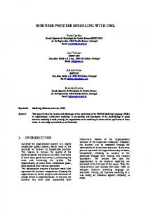
3. Database Operations Modeling Most database products define functions, packages, or stored procedures to isolate portions of operations, hide implementation details and improve performance. These operations can be very complex and should be modeled in the same way as application level operations. We can use a use case to represent an operation at requirement analysis level and use activity diagram, sequence diagram, communication diagram and state machine diagram at design and implementation level. Here is a system stored procedure dt setpropertybyid used in SQL Server 7.0. It is implemented in Transact-SQL. CREATE PROCEDURE dbo.dt_setpropertybyid @id int, @property varchar(64), @value varchar(255), @lvalue image as set nocount on declare @uvalue nvarchar(255) set @uvalue = convert(nvarchar(255), @value) if exists (SELECT * FROM dbo.dtproperties WHERE objectid=@id AND property=@property) begin UPDATE dbo.dtproperties SET value=@value, uvalue=@uvalue, lvalue=@lvalue, version=version+1 WHERE objectid=@id AND property=@property end else begin
Declare and assign variables [property doesn’t exist] [property exists] Update property, version++
Insert property
Figure 12. Stored procedure activity diagram INSERT dbo.dtproperties (property, objectid, value, uvalue, lvalue) VALUES (@property, @id, @value, @uvalue, @lvalue) end The above stored procedure can be modeled using use case as shown in Table 1. We can use activity diagram, sequence diagram and other diagrams to model this stored procedure at requirement, analysis, design and implementation level. By combining all these diagrams together, we will have a much better understanding of complex database operations. Some CASE tools such as Rational Rose provide the functionality to attach activity diagram and state machine diagram to stored procedures. But forward and reverse engineering capability has not been implemented yet. Figure 13 shows the sequence diagram at implementation level. We use Select, Update and Insert statement as building blocks
sd dt_setpropertybyid @id int, @property varchar(64), @value varchar(255), @lvalue image
:dtproperties
SELECT SELECTION:projectID=@id AND property=@property alt
UPDATE SELECTION:objectid=@id AND property=@property SET:value=@value, uvalue=@uvalue, lvalue=@lvalue, version=version+1
[exist] [not exist]
INSET SET:property=@property, objectid=@id, value=@value, uvalue=@uvalue, lvalue=@lvalue
Figure 13. Stored procedure sequence diagram
and place them inside predefined framed part such as alt to represent conditional execution. Input and output parameters are listed in a separate compartment below diagram name.
4. Conclusion In this paper, we proposed a framework that can be used to model database-related operations using a set of UML diagrams. We believe that this approach will provide endusers and developers with a unified view of the whole system and bring the power of UML to database domain. As the next step of our research, we plan to analyze more complex database operations in details. We will formalize our model using UML metamodel. We hope to develop algorithms used for reverse engineering existing applications. Eventually tools can be built based on these algorithms.
References [1] Anreas Behm, et al., “On Migration of Relational Schemas and Data to Object-oriented Database Systems”, Proceedings of the 5th International Conference on Re-techologies for Information Systems, December 1997, pp.13-33.
[2] Tomas A. Bruce, Designing Quality Databases with IDEF1X Information Models, Dorset House Publishing Company, Incorporated, New York, USA, October 1992 [3] Peter Chen, “The Entity-Relationship model - Toward a unified view of data”, ACM Transactions on Database System, Vol.1, No.1, March 1976, pp.9-36. [4] Edgar F. Codd, “A relational model of data for large shared data banks”, Communications of ACM, Vol.13, No.6, June 1970, pp.377-387. [5] Hans-Erik Erikson, et al., UML 2 Toolkit, Wiley Publishing, Inc. Indianapolis, Indiana, USA, 2004 [6] Gordon C. Everest, Database management: Objective, System Functions, and Administration, McGraw-Hill, New York, USA, 1986 [7] Martin Gruber, Understanding SQL, SYBEX Inc., Alameda, California, USA, 1990 [8] Davor Gornik, “UML Data Modeling Profile”, White Paper, Rational Software. May 2002 [9] Terry Halpin and Anthony Bloesch, “Data modeling in UML and ORM: a comparison”, Journal of Database Management, Vol. 10, No. 4, Idea group Publishing Company, Hershey, USA, October 1999, pp.4-13. [10] Robert J. Muller, Database Design for Smarties: Using UML for Data Modeling, Organ Kaufmann Publishers, Inc. San Francisco, California, USA, 1999 [11] Eric J. Naiburg and Robert A. Maksimchuk, UML for database design, Addison-Wesley, Boston, MA, USA, 2001 [12] William J. Premerlani, et al., “An Approach for Reverse Engineering of Relational Databases”, Communications of the ACM, Vol. 37, No.5, May 1994, pp.42-49. [13] Shekar Ramanathan, et al., “Reverse Engineering Relational Schemas to Object-oriented Schemas”, Technical Report No. MSU-960701, Mississippi State University, 1996 [14] James Rumbaugh, Ivar Jasobson, and Grady Booch, The Unified Modeling Language Reference Manual, AddisonWesley, Reading, MA, USA, 1999 [15] Toby J. Teorey, Dongqing Yang, and James P. Fry, “A logical design methodology for relational database using the extended entity-relationship model”, Computing Survey, Vol.18, Issue 2, June 1986, pp.198-222. [16] The UML and Data Modeling, White Paper, Rational Software, 2003 [17] Unified Model Language specification, Object Management Group, http://www.omg.com [18] Unified Modeling Language: Superstructure 2.0 pct/03-0706, Object Management Group, 2003