Jan 9, 2009 - System (GPS) for the coordination of a group of mobile robots. ..... This is a robust and lightweight, packet based, binary .... phones to a local network or to the internet. .... the calculation of intersections for trilateration or triangulation is ...... must be answered with the same payload as an acknowledgment.
University of W¨ urzburg Faculty of Computer Science Institute of Robotics and Telematics
A Relative Localization System for Mobile Robot Formations
Diploma Thesis in
Computer science presented by
Manuel Stahl
A Relative Localization System for Mobile Robot Formations
Diploma Thesis in
Computer science presented by
Manuel Stahl born on 25.12.1982 in Ochsenfurt, Germany
Completed at the
University of W¨ urzburg Faculty of Computer Science Institute of Robotics and Telematics Supervisor: Prof. Dr. K. Schilling Dipl. Inf. M. Hess Delivery date of the Thesis: 9th January 2009
Acknowledgement First I want to thank Prof. Dr. Klaus Schilling for the possibility to work freely on such an interesting project. Thereby I had the chance to gain much experience in the practical design and theoretical analysis of robotic systems. Moreover I want to express my gratitude to my supervisor Martin Hess who gave me insight into the challenges of working with groups of mobile robots and supported me in writing this thesis. Special thanks go to Dieter Ziegler, Stefan Busch and Daniel Eck for the inspiring discussions we had as well as the whole team of the robotics hall for the comfortable atmosphere. Finally I want to thank Sven W¨achtler for spending his time proof-reading this thesis and my girlfriend Julia for motivating and supporting me.
Declaration I hereby declare that this submission is my own work and that, to the best of my knowledge and belief, it contains no material previously published or written by another person nor any material which to a substantial extent has been accepted for the award of any other degree or diploma of the university or other institute of higher learning, except where due acknowledgment has been made in the text.
W¨ urzburg, the 9th January 2009 (Manuel Stahl)
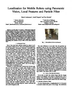
Figure 0.1: The OutdoorMERLIN rover with attached ultrasonic sensors
Abstract This diploma thesis project describes a localization system to measure the relative poses of mobile robots driving in a formation. An overview of existing localization systems is given and several possible measurement methods are discussed. An attempt has been made to characterize the suitability of the Global Positioning System (GPS) for the coordination of a group of mobile robots. A single frequency GPS receiver was found not to be precise enough to avoid collisions of the vehicles. It is also not available indoors, so an additional system based on ultrasonic sensors has been designed and implemented. To find the most suitable localization algorithm, the achievable accuracies were compared in worst case simulations. The major advantage compared to existing systems is the reuse of ultrasonic obstacle detection sensors that are already available on most mobile robots, and that no precise time synchronisation between the robots is required. The sensors can be placed at arbitrary locations on the robot. This minimizes the effort of integrating the system into existing multi-vehicle platforms. The computational complexity is kept low so that even a low cost micro controller is fast enough to run the derived algorithm for real time measurements. The selected hardware design is robust and can survive harsh conditions in outdoor environments. The proposed localization system was installed on the OutdoorMERLIN rovers. With these vehicles several experiments were made to test the reliability and accuracy of the system in real world conditions.
i
Contents 1 Introduction 1.1 Mobile robots . . . . . . . . . . . . . . . . 1.2 Motivation . . . . . . . . . . . . . . . . . . 1.3 Outline . . . . . . . . . . . . . . . . . . . . 1.4 Background: The MERLIN platform . . . 1.4.1 OutdoorMERLIN Hardware . . . . 1.4.2 MERLIN Operating System . . . . 1.4.3 MERLIN Control Software . . . . . 1.4.4 MERLIN Communication Protocol
. . . . . . . .
1 1 1 2 3 3 4 4 4
. . . . .
5 5 5 5 6 7
3 State of the art 3.1 Beacon / landmark based systems . . . . . . . . . . . . . . . . . . . . . . 3.2 Mobile systems . . . . . . . . . . . . . . . . . . . . . . . . . . . . . . . . 3.3 Discussion . . . . . . . . . . . . . . . . . . . . . . . . . . . . . . . . . . .
9 9 11 14
4 Localization system design 4.1 Simulations . . . . . . . . . . . . . . . . . . . . 4.2 Distance measurements without synchronization 4.3 Detection of erroneous measurements . . . . . . 4.4 Relative position . . . . . . . . . . . . . . . . . 4.5 Relative orientation . . . . . . . . . . . . . . . . 4.6 Communication sequence . . . . . . . . . . . . .
. . . . . .
15 16 17 19 19 24 25
. . . . .
27 27 27 29 30 31
. . . . . . . .
. . . . . . . .
2 Localization techniques 2.1 Vision . . . . . . . . . . . . . . . . . . . . . . 2.2 Received signal strength indication (RSSI) . . 2.3 Time of arrival (ToA) or Time of flight (ToF) 2.4 Time difference of arrival (TDoA) . . . . . . . 2.5 Angle of arrival (AoA) . . . . . . . . . . . . .
5 Implementation 5.1 Hardware systems . . . . . . 5.1.1 Ultrasonic sensor . . 5.1.2 Sensor controller . . 5.1.3 Connection diagram 5.2 Software . . . . . . . . . . .
ii
. . . . .
. . . . .
. . . . .
. . . . .
. . . . .
. . . . .
. . . . .
. . . . .
. . . . .
. . . . .
. . . . . . . .
. . . . .
. . . . .
. . . . . . . .
. . . . .
. . . . . .
. . . . .
. . . . . . . .
. . . . .
. . . . . .
. . . . .
. . . . . . . .
. . . . .
. . . . . .
. . . . .
. . . . . . . .
. . . . .
. . . . . .
. . . . .
. . . . . . . .
. . . . .
. . . . . .
. . . . .
. . . . . . . .
. . . . .
. . . . . .
. . . . .
. . . . . . . .
. . . . .
. . . . . .
. . . . .
. . . . . . . .
. . . . .
. . . . . .
. . . . .
. . . . . . . .
. . . . .
. . . . . .
. . . . .
. . . . . . . .
. . . . .
. . . . . .
. . . . .
. . . . . . . .
. . . . .
. . . . . .
. . . . .
. . . . . . . .
. . . . .
. . . . . .
. . . . .
. . . . . . . .
. . . . .
. . . . . .
. . . . .
Contents 5.2.1 5.2.2 5.2.3
Localization module . . . . . . . . . . . . . . . . . . . . . . . . . Modification of the ultrasonic module . . . . . . . . . . . . . . . . Formation control module . . . . . . . . . . . . . . . . . . . . . .
6 Experiments 6.1 GPS . . . . . . . . . . . . . . . . . . . . . . . . . 6.2 Static accuracy and precision . . . . . . . . . . . 6.2.1 Performance at different relative locations 6.2.2 Failure rate of the localization system . . . 6.2.3 Influence of obstacles . . . . . . . . . . . . 6.3 Dynamic performance . . . . . . . . . . . . . . . 6.3.1 Maximum distance . . . . . . . . . . . . . 6.3.2 Accuracy of the relative position . . . . . . 6.3.3 Accuracy of the relative orientation . . . .
. . . . . . . . .
. . . . . . . . .
. . . . . . . . .
. . . . . . . . .
. . . . . . . . .
. . . . . . . . .
. . . . . . . . .
. . . . . . . . .
. . . . . . . . .
. . . . . . . . .
. . . . . . . . .
. . . . . . . . .
. . . . . . . . .
31 33 34 37 37 38 40 43 44 45 45 46 48
7 Conclusion 51 7.1 Properties of the presented localization system . . . . . . . . . . . . . . . 51 7.2 Further work . . . . . . . . . . . . . . . . . . . . . . . . . . . . . . . . . 52 A SRF02 interface
53
B CAN messages 55 B.1 Sensor data . . . . . . . . . . . . . . . . . . . . . . . . . . . . . . . . . . 55 B.2 Commands . . . . . . . . . . . . . . . . . . . . . . . . . . . . . . . . . . 56 C Merlin communication protocol messages 59 C.1 Localization protocol (ID = 0x7A) . . . . . . . . . . . . . . . . . . . . . 59 C.2 Formation control protocol (ID = 0x7B) . . . . . . . . . . . . . . . . . . 61 D Electronic schematics
63
E Contents of the attached CD-ROM
65
Acronyms
67
Figures and Tables
70
Bibliography
73
Weblinks and datasheets
77
iii
1 Introduction This diploma thesis is about the relative localization of groups of mobile robots. A localization system based on ultrasonic measurements has been developed. It has been implemented on the OutdoorMERLIN rover to verify the performance in real world experiments. This chapter introduces cooperating mobile robots, outlines the motivation for the development of such a system and gives an overview of the platform for Mobile Experimental Robots for Localization and Intelligent Navigation (MERLIN).
1.1 Mobile robots The first commercial success for mobile robots in industry was achieved with autonomous transportation systems to optimize the flow of materials. These vehicles are guided on predefined ways through the facility and don’t need to localize themselves. But also higher grades of autonomous navigation were developed [20]. The next step was made with small, autonomous household gadgets like vacuum cleaners and lawn-mowers. These systems have a clearly defined task and only one integrated and specialized tool. They are also often not able to localize themselves, so the work area has to be limited by walls or artificial borders like inductive wires. A more recent area of research are cooperating mobile robots. Search and rescue scenarios [8] and exploration of hazardous areas benefit from distributed systems of smaller vehicles. The time needed to complete all tasks decreases with the number of robots. Most publications dealing with the control of robot formations rely on a working localization system [21, 10] or only describe such a system theoretically [18].
1.2 Motivation Autonomous mobile robots are an important research topic of the Institute of Robotics and Telematics at the University of W¨ urzburg. Especially nonholonomic rovers with Ackermann steering are in the focus. Tele-operation of semi-autonomous robots is still state of the art in most robotic applications. To help the operator to concentrate on his main task, different assistance systems [29] were developed. This is particularly necessary for formations of mobile robots that are controlled by only one operator. To keep the shape of the formation it is essential for a member of that group to know the relative positions of the other vehicles. Therefore the MERLIN platform was extended to facilitate experiments with groups of mobile robots. Recent work includes dynamic formation control and adaption as well
1
Chapter 1 Introduction as optimization of path scheduling [14]. Currently the hardware experiments are carried out with the IndoorMERLIN family of robots. Localization on the IndoorMERLIN rovers is established with dead-reckoning based on odometry data. There are encoders to measure the wheel rotation and a gyroscope for the angular rate in the yaw axis. The accuracy of dead-reckoning decreases vastly over time, but on a flat and clean indoor ground surface it can be used for short time experiments [27]. To make use of the whole spectrum of test areas available at the University of W¨ urzburg and to be able to generate more realistic test scenarios, the OutdoorMERLIN is a suitable test platform. Odometry is not available for this vehicle, since its wheels encounter huge deformations and slippage on different surfaces. Therefore a different localization system is needed. It must be reliable in harsh environmental conditions and on a heavily vibrating and fast moving robot. To avoid collisions of the rovers, the accuracy shall be in the range of the robot’s size. Space is very valuable on small robots, consequently as many of the existing components as possible should be reused. The tasks of this thesis are: • Investigation of existing localization methods and their suitability for mobile robots • Development of a robust localization system for groups of small mobile robots • Implementation of the system on the OutdoorMERLIN rover • Verification of the performance of the system in real world tests
1.3 Outline After this introduction, the thesis is split into these chapters: Chapter 2 explains the physical effects that can be measured and used in localization systems, as well as the related algorithms to calculate positions. Chapter 3 gives an overview of other localization systems, compares their properties and analyzes their suitability for mobile robots. Chapter 4 describes the developed localization system theoretically and presents the simulations that were made to estimate the performance. Chapter 5 is about the involved hardware systems and how the localization algorithm was implemented to form a working system. Chapter 6 presents the design of the experiments and the results that were gained. Chapter 7 reviews the main properties of the developed system and gives an outlook for further research.
2
1.4 Background: The MERLIN platform
1.4 Background: The MERLIN platform In this section an overview of the MERLIN platform is given with special emphasis on the hardware system of the OutdoorMERLIN.
1.4.1 OutdoorMERLIN Hardware The OutdoorMERLIN rover is a small car-like vehicle that has been designed to be able to travel on rough terrain at high speed and to survive harsh conditions like rain, snow and dust. It is about 60cm long, 45cm wide and has a height of 40cm. Chassis The chassis of the OutdoorMERLIN consists mainly of aluminium parts for the structure and enforced steel for the drive train. Its permanent four wheel drive is powered by a strong brushless motor that allows high speeds (up to 15m /s ) and climbing steep hills. A high torque servo controls the Ackermann steering of the vehicle. All actuators needed for driving as well as their controllers and the battery pack are mounted in the lower part of the chassis. On top of that a flat aluminium board with rollover bars protects the electronic components. Half of this board is covered with the basic system, the other half can be equipped with optional sensors and other payload. Electronics The main electronics are composed of five systems: • The battery pack consists of 18 NiMH cells with a capacity of 10Ah, divided into two units of 9 cells. These units are specially designed to be very robust and can be attached without any tools. • The motor controller powers a brushless motor and has a peak output current of 110A. There is a speed regulator integrated, which is controlled via a Pulse Width Modulation (PWM) signal from the main microcontroller. It has an additional RS232 interface to provide sensor and failure information. • The power board provides regulated outputs for 5V, 12V and 24V from the battery supply. It can measure the currents of all outputs and its internal temperature. • The controller board includes a C167 microcontroller with interfaces to six RS232 devices, an I2 C bus, a CAN bus, four A/D converter channels with low-pass frequency filters, four PWM channels and four general purpose I/Os. • The PC104 industry-standard computer provides higher level processing power and an interface to a Wireless Local Area Network (WLAN).
3
Chapter 1 Introduction Sensors The OutdoorMERLIN can be equipped with different sets of sensor systems. A basic configuration that is always available consists of a gyroscope to measure the angular rate in the yaw axis, a GPS receiver with an update rate of 4Hz and 10 ultrasonic transceivers around the vehicle for range measurements. Moreover the motor controller is able to sense the motor’s speed and its power output.
1.4.2 MERLIN Operating System The modular MERLIN Operating System (MOS) [7] runs on a C167 microcontroller. It is designed to allow Cooperative Multi Tasking, which means every task runs until it returns the control to the operating system. Preemption from a task with higher priority is not possible. A scheduler can run the tasks at specific intervals in multiples of 10ms. This design minimizes interference between the tasks. Thus concepts like semaphores and queues for inter task communication are not necessary. The drawback of this simplicity is that reaction to communication events can not be guaranteed to take place in less than 10ms. This is sufficient for most control applications but not for Time of Flight measurements (see section 2.3).
1.4.3 MERLIN Control Software The user interface to the MERLIN robots is realized as a Rich Client Platform (RCP) with the Eclipse framework [4]. It consists of a basic set of plugins that encapsulate the MERLIN Communication Protocol (MCP) and some commonly used widgets for visualization. All additional functionality of the MERLIN platform, like access to sensor information and control of assistance behaviour, is grouped into optional plugins. The advantage of the Eclipse framework as an underlying system is the possibility to freely arrange the layout of the sensor visualization and control inputs to meet the demands of the current task. Such a configuration is called a perspective.
1.4.4 MERLIN Communication Protocol Communication with the MERLIN Control Software (MCS) [4] and between vehicles is established by using the MCP. This is a robust and lightweight, packet based, binary protocol that can be used with every serial transceiver or it can be tunneled over standard communication protocols such as the User Datagram Protocol (UDP). The tunneling and routing is transparent to the end nodes which makes it impossible for these to control the delay and jitter of the messages. The default communication method is therefore not suitable for synchronizing the robots in a microsecond scale. The MCP also has a modular design and specifies so called protocol identifiers to group messages that belong to the same subsystem. A module of the MOS can register itself to participate in the exchange of messages for one or more protocol identifiers.
4
2 Localization techniques Localization is used in many applications and therefore a lot of research has been done in that field. In this chapter an overview of the most important techniques is given. In the following sections the focus is on localization in 2D space.
2.1 Vision Most animals and also humans use vision for localization. This leads to the assumption that it is a practical method in many use cases. Research has brought up efficient algorithms to handle that problem by feature detection and stereo vision. Nevertheless, getting a reasonable update rate in real-time applications needs a lot of processing power, and to cover a 360 field of view, complex optical systems are required. Recently a new kind of camera for vision with depth information has been developed. These Photonic Mixer Devices (PMDs) [25] use the same principle for distance measurements as explained in section 2.3. They provide distance data for every pixel in their field of view.
°
2.2 Received signal strength indication (RSSI) The amplitude of an electromagnetic or acoustic wave can be an indicator of the distance to the signal’s source. In an environment without obstacles the relation can be described as S ∼ d12 [11]. A realistic scenario introduces shielding and reflection, which leads to a signal strength distribution that can only be characterized or mapped empirically [15]. From such a map a mobile unit can try to find the locations which match its own observations best.
2.3 Time of arrival (ToA) or Time of flight (ToF) Another physical property of a wave is its propagation speed. If this speed is constant on the way between a sender and a receiver and a line of sight propagation is possible, the distance d can be calculated as d = c · ∆t where c is the propagation speed and ∆t is the time between sending and receiving. A synchronized, absolute time base on the sender and the receiver is needed to determine the Time of Flight (ToF) ∆t. The required precision of the synchronization depends on the propagation speed and the desired distance accuracy. For acoustic waves
5
Chapter 2 Localization techniques
°
in air (cair ≈ 343m /s at 20 C [11]) and an accuracy of 1mm the deviation of the clocks must be less than d/cair = 2.92µs. For localization with absolute distance information an algorithm called trilateration is used. It requires distance measurements to three fixed nodes, for which the position is known. The algorithm can be visualized geometrically with the intersection of three circles as in figure 2.1. Each circle is defined by a nodes position (the circle center) and the corresponding range measurement (the circle’s radius).
Figure 2.1: ToA: Intersection of circles Two circles have two ambiguous intersection points, so a third distance to a node that is not co-linear with the others is required.
2.4 Time difference of arrival (TDoA) In literature we can find two different descriptions for TDoA. One takes the time of flight difference of signals with distinct propagation speed (we will call this signal delay), the other refers to the time difference when the signal is detected on receivers at different locations (we will call this receive delay). With the signal delay approach it is possible to determine the exact distance between the sender and the receiver. In most applications two signals with substantial different speeds (e.g. acoustic and electromagnetic) are used and the ToF of the faster signal can be neglected. This is similar to ToA by synchronizing the clocks with the fast signal and measuring the distance with the slower signal and thus trilateration as in 2.3 can be used. Knowing the receive delay of two receivers reduces the possible locations of the sender to an area described by a hyperbolic function as can be seen in figure 2.2. With a third receiver, an intersection between the resulting functions can be calculated. The advantage is, that no information about the transmission time is needed.
6
2.5 Angle of arrival (AoA)
Figure 2.2: TDoA: Intersection of resulting hyperbolic functions
2.5 Angle of arrival (AoA) A triangle is completely defined by two angles and the length of one side. If we place two receivers, which can measure angles, at a fixed distance, we know all necessary parameters to calculate the position of the triangle’s third corner. This is called triangulation. Figure 2.3 shows this relationship. The method is one of the oldest in navigation and still state of the art in land survey. For manual measurements an instrument called theodolite is used to take the bearing angles of marked locations. Automatic measurement of angles is often done with rotating receivers that have a very narrow field of view. When the signal of an omnidirectional transmitter is detected by the receiver, its current angular position is equivalent to the Angle of Arrival. The advantage is that only the measurement of two nodes is required.
Figure 2.3: AoA: Calculating the position from angles in a triangle
7
3 State of the art Localization is required in many applications, which led to a broad spectrum of different systems used in research and also commercially. Not all of them have been designed for mobile robots, but nevertheless can be used for that task. In this chapter some of the developed systems are presented and their suitability for the localization of groups of mobile robots is discussed.
3.1 Beacon / landmark based systems Beacon or landmark based systems work with a global coordinate system. They consist of a number of nodes for which the position is well known. The difference between beacons and landmarks is that the beacons are active (i.e. send out some signal or measure a signal) where in contrast the landmarks are passive and can be detected by the moving vehicle. The systems can be further divided into systems in which position information is calculated on the vehicle (onboard systems) and systems in which the calculation is done on an external computer (offboard systems).
WLAN fingerprinting WLAN is a popular standard for connecting personal computers, laptops and even mobile phones to a local network or to the internet. When internet access providers began to subsidize WLAN routers with their contracts, the market for these devices exploded and WLAN became a pervasive technology especially in urban areas. Recently more and more researchers and also companies were attracted by that phenomenon when they realized that the ubiquitous presence of WLAN can be used for localization by using the Received Signal Strength Indication (RSSI). Several publications are related to that topic and it has already been integrated into commercial products like the iPhone [37]. The achievable accuracy depends on the amount of base stations and the structure of buildings, but is never more accurate than one meter [22, 5]. Direct measurement of the orientation is not possible. Another radio frequency technology that is wide spread in warehouses is Radio Frequency Identification (RFID). In [13] a probabilistic algorithm is presented that can be used to localize a robot relative to RFID tags in its vicinity.
9
Chapter 3 State of the art
WLAN round trip time A very interesting approach to measure the distance between two standard WLAN nodes was published by Gunther and Hoene [12]. They developed statistical methods to analyze the Round Trip Time (RTT) of the exchanged packets. Though the hardware timers of commercial WLAN hardware are not precise enough to measure the ToF directly, the proposed algorithms allow an estimation of the distance between the nodes with an accuracy of a few meters. The authors claim that this practice is superior to RSSI measurements.
Location-aware systems There is a great number of localization systems, that were developed for ubiquitous computing, for which the infrastructure has to know the location of its users. They have all been designed to cover large indoor areas with as few static nodes as possible. Maximum accuracy was not in the main focus. What makes these systems interesting for mobile robot localization are the relatively small mobile units and the different measurement techniques that have successfully been implemented. TRIP [17] is a low-cost, vision-based localization system in which a single camera observes a room and detects the location of special markers. Active Badge [33] and PARCTAB [28] are based on infrared signal strength, SpotOn [15], RADAR [1] and FLARE [6] use radio-frequency signal strength while Cricket [23] uses ultrasonic measurements.
SnowBat SNoW Bat [3] is a decentralized localization system to be used in a Wireless Sensor Network (WSN). Each node in the network is equipped with an ultrasonic measurement unit. The system supports several scheduling methods for localization, but the most interesting for our application is the mode at which the mobile unit initializes the acquisition of its position. To achieve this it sends a multicast message called chirp allocation vector (CAV) over its wireless communication link that informs and synchronizes the desired nodes that take part in the positioning. The localization module is very deeply integrated into the node’s software, so that no major delay is introduced by the communication stack. The CAV contains information about the time and the number of ultrasonic pulses that the mobile unit will send. As soon as the static nodes have received all the pulses they will calculate their distance to the transmitter and send it to the mobile node combined with their own known position. Calculation of the position is done on the mobile node (online system). The system is able to calibrate the position of the static nodes automatically. This drastically reduces the time for deployment. The accuracy is mentioned to be better than 15mm. In [35] Yi and Choi describe a similar system, at which the mobile robot has full control over the fixed ultrasonic transmitters in the workspace. The robot is equipped
10
3.2 Mobile systems with two receivers, so it can acquire its position and heading. The authors use an Extended Kalman Filter (EKF) to combine the odometry data of the robot with the information of the ultrasonic localization system. The position error is less than 25mm in a workspace of 1.5m × 1.5m × 2.5m.
Global navigation satellite systems A Global Navigation Satellite System (GNSS) consists of a network of satellites that allow a receiver unit to measure its global position in earth centric coordinates. The unit needs to receive the signal of at least four satellites to synchronize its clock and to acquire its location. The Global Positioning System (GPS) is probably the most used navigation system world wide. Since the Selective Availability (SA) has been disabled, it provides an accuracy of a few meters with low-cost hardware and goes up to the centimeter level with high-end, multi-frequency receivers also for civilian applications [38]. Soon Galileo [39] will improve the performance, as on average, more satellites will be in view of a receiver. Despite this, there are still a lot of situations at which GPS is not available, e.g. between tall buildings, in dense forests, under water and especially indoors.
3.2 Mobile systems Mobile systems combine all necessary sensors for localization on the vehicles. Depending of the robot’s capabilities, the processing is not always done onboard. In general no artificial objects in the environment are required.
Vision In [31] a catadioptric camera system on the top of a robot is used to acquire omnidirectional images of the vehicle’s surrounding with a rate of 15Hz. Each robot in a formation is marked with a different color. The localization system can detect the direction to the vehicles and also roughly estimate the distance from the colored marker’s size in the image. For a successful localization, a group of at least three robots is required and every robot needs to see all the others. The computation is done offboard on a centralized system. While the formation is moving 15%-20% of the images of each robot are lost due to corruption of transmission. This leads to longer phases without localization data. For a distance of one meter between the robots, the deviation is less than 20cm. In [16] a vision based system is combined with the measurements of a laser scanner. The implemented filtering approach is very interesting as it is able to deal with multiply hypothesis of a robots location. It is not explicitly mentioned what kind of processing system was used, but the vision approach together with a particle filter indicate that a rather powerful CPU is needed. The position accuracy is stated to be better than 10cm.
11
Chapter 3 State of the art
Dead-reckoning Based on the knowledge of its current speed and heading, a vehicle can integrate its position over time. This method is heavily used on single-robot systems, if only local information about the vehicle’s movement relative to the ground is available. It can also be used in combination with absolute localization systems to bridge the gap between position updates. For multi-robot applications, the relative position of all vehicles must be known for a particular time. From there on each robot calculates only its own location relative to the starting pose. This information can be shared over a communication link and therefore the robots know each others position. The accuracy of the position information degrades with the time the robots are travelling [34]. This is caused by errors in the numerical integration and by sensor errors that get accumulated. It is especially a problem for the measured heading as a small error will result in a huge position deviation after the robot has moved a certain distance even if no additional error is included.
SLaM Simultainous Localization and Mapping (SLaM) is a very common feature of most medium size mobile robots built today. It requires a high resolution obstacle detection mechanism, like a laser scanner. The robot acquires a map of its vicinity while driving around and tries to locate itself relative to the features it extracts of this map. If a group of robots moves in the same environment, the individual vehicles will likely create similar maps or can even share one distributed map. If all robots can locate themselves inside the map and communicate this information within the group, each robot knows the position of the others. The performance of SLaM is best if the environment is static and provides enough unique features, so that the correlation of sensor readings with the map do not lead to ambiguous estimations. Contrary to that, a group of robots will itself impose a lot of dynamics to the environment. Furthermore, in outdoor scenarios the feature density is often very low [2], so there are not enough objects in the sensor range to get a good location estimate.
Moorebots For the Moorebots of the EPFL, J. Pugh developed a mobile localization system based on the RSSI of a modulated infrared signal [24]. An accuracy of 3cm to 20cm (depending on the distance) in position and less than 10 in orientation seems very good for a RSSI based system. The advantage is that no additional communication channel is needed, as it is possible to transfer data on the infrared channel. The module is very small, but needs an omnidirectional view around the vehicle. Furthermore, it is not stated, if the system works outdoors as it is very likely that the signal strength might be attenuated by rain, fog or dust.
°
12
3.2 Mobile systems
Millibots The Millibots [32] project at Carnegie Mellon University combines dead reckoning and ultrasonic distance measurements on very small sized robots. The vehicles have one omnidirectional ultrasonic transducer and can therefore only measure distances to the others but not the orientation. The size and the design of the millibots limit their field of application to indoor environments. A maximum likelihood estimator tries to correct the dead reckoning errors with the distance information of all robots. All the complex calculations are done on a centralized unit and it is necessary for all robots to have contact with that unit. Only one robot can move while the others serve as beacons with known locations and measure the distance to this robot.
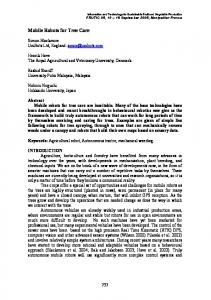
Anonobots At the University of Wyoming Spears et al. developed a localization system for their anonobots [19]. It uses three omnidirectional ultrasonic transducers and a radio module for synchronization. The transducers were made omnidirectional by placing parabolic cones above them. Their geometric placement effectively reduces the complexity of the trilateration algorithm. The drawback of the omnidirectional sensors is that they need an exposed placement above the robot. The maximum distance between the vehicles involved in the localization is 3.5m. The standard deviation of the position data is less than 50mm at an update rate of 4.17Hz.
Figure 3.1: The Anonobots of the University of Wyoming A very similar system was implemented by Rivard et al. [26]. The only difference is that they use one separate transmitter and three receivers placed around it. The performance is much better as the system is said to have a precision of 8mm in distance and of 3 in the angular component over a 6.7m range.
°
13
Chapter 3 State of the art Both projects address the same scenarios that are also of interest for the system to be developed. But the hardware components are very fragile and are not protected from the influence of harsh conditions like rain or snow. Also a rollover of the vehicle would probably cause severe damage. The design and the placement of these components makes it impossible to shield them belatedly.
3.3 Discussion For global systems based on beacons there is a direct connection between the density of the nodes and the achievable accuracy of the position information. In general, global systems have a big advantage regarding the numerical stability of the localization algorithm. The object to localize is normally inside a frame defined by the beacons or landmarks. Therefore the calculation of intersections for trilateration or triangulation is possible with higher precision. The systems are designed either for indoor or for outdoor use but not both. The major drawback of global systems is their reduced availability. Either they won’t cover all desired locations (like GPS or WLAN based systems) or they have to be installed at the desired work area. For the designated scenarios this leads to the assumption that a mobile system is more adequate. As stated in chapter 1 dead-reckoning based on odometry data is not possible with the OutdoorMERLIN. It also allows only short time experiments and is therefore no alternative that can be considered. The sensors that are required for SLaM are relatively large compared to the dimensions of the OutdoorMERLIN robot. The optimal environment for SLaM is static and must be properly structured to achieve a high accuracy. This is probably not the case in outdoor scenarios with a group of mobile robots. The mobile systems based on RSSI measurements need no previously acquired map but the attenuation of the signal is hard to estimate for all possible conditions. To keep the distance deviation low the systems must be calibrated for a specific operational area. As the localization system should be operational under changing conditions for example at the transition from indoor to outdoor another measurement method is preferred. Mobile systems based on ultrasonic measurements have a reasonably good accuracy. But they often use omnidirectional transceivers that must be installed on top of the robot and can not be integrated at protected locations inside the chassis. Nevertheless ultrasonic measurements seem to be most reliable compared to other systems based on distance measurements. They are also only very slightly affected by environmental conditions like dust or fog that make visual measurements impossible.
14
4 Localization system design There are several methods for localization, that were successfully used in different applications. The most important are explained in chapter 2. As it is shown in chapter 3, some of these techniques can also be applied on small mobile robots and achieve a reasonably accurate performance. For the proposed scenarios, it is preferable that the operational area is not limited by the placement of landmarks or beacons, so a purely mobile system should be implemented. Our desired deployment on the OutdoorMERLIN rover puts some more constraints on the system design. The sensors have to be placed at protected locations around the vehicle, where the field of view is limited by the robots chassis. The localization system should be operational in most circumstances, but it must at least survive the harsh conditions like rain or low temperatures, that the OutdoorMERLIN is regularly exposed to. As much as possible of the available hardware of the OutdoorMERLIN should be reused. There are already two sensor systems onboard that are suitable for localization, the GPS modules and the ultrasonic sensors. Obviously the GPS would be the simplest system to use, but there are two major problems preventing its exclusive application. First, it is not available indoors and second the relative drift of two GPS receivers is in the order of a few meters, which could cause collisions of robots in a narrow formation. See chapter 6 for the experimental results. This chapter describes the theoretical part of the localization system. To find the best localization technique that can be implemented with the onboard ultrasonic sensors, several Matlab simulations were made. The technique that promised the best accuracy was chosen and an algorithm for it was developed. In the next sections the vehicles involved in the localization will be called robot A and robot B. The intention of a pairwise relative localization in 2D space, is for robot A A T A to measure and calculate the pose (xA B yB θB ) of robot B in its own coordinate system and, if possible, at the same time for robot B to measure and calculate the pose B B T (xB A yA θA ) of robot A. The first step to get another robot’s pose, is to measure and calculate its position. The methods Time Difference of Arrival (TDoA) and Time of Arrival (ToA) have been considered, as it is not possible to measure angles with the available ultrasonic sensors. In simulations of worst case scenarios, the most suitable method was selected. To simplify the notation, the coordinates in the following sections are all assumed to be in robot A’s local coordinate system, until denoted otherwise.
15
Chapter 4 Localization system design
4.1 Simulations In order to estimate the theoretically achievable accuracy, a number of MATLAB simulations were done. It was assumed that the error of the ultrasonic distance measurement is normally distributed and has a standard deviation of 1cm. This seems reasonable for most commercial ultrasonic sensors and was verified in various tests (see chapter 6). The simulations were made for the minimum amount of sensors that are necessary to get a unique solution from the localization method. The timebases of the robots based on the MERLIN platform are not synchronized, so the obvious solution is to use a TDoA design. This technique works solely with time differences that can be measured on a single robot.
(a) probability added
(b) probability multiplied
Figure 4.1: Time difference of arrival probability distribution Figure 4.1 shows the simulated probability distribution of a TDoA measurement. The virtual sensors A,B and C were placed on the red circles. Two pairs (AB and BC) of sensors were observed. A fictional distance measurement difference was predefined ((a − b) = 21cm, (c − b) = 41cm). For every pixel of the images the probability was calculated, that a sender at the location of this pixel results in the given measurement. A brighter the pixel indicates a higher probability. In the left image the probabilities of two sensor pairs were added to see the effect of the measurement deviation on the hyperbolic functions, which diverge with the distance from the receivers. Further simulations revealed, that this effect is even worse if the measurement difference is close to the distance of the receivers, i.e. (a − b) ≈ AB. In the right image the probabilities were multiplied to get the distribution of a combined measurement with three sensors.
16
4.2 Distance measurements without synchronization From the simulation we can conclude, that the angular accuracy would be acceptable. But the deviation in the distance can become very large, due to the fact that the hyperbolic functions are nearly parallel at their intersection point. For TDoA to be a useful localization method, the distance between the fixed sensors A,B and C must be large compared to the standard deviation of the sensors. Or the node to localize must be inside a frame defined by the fixed sensors so that the hyperbolic functions intersect with an obtuse angle. Both requirements are not met for a small mobile robot that uses acoustic distance measurements.
(a) probability added
(b) probability multiplied
Figure 4.2: Time of arrival probability distribution Figure 4.2 shows the same simulation for a ToA measurement. This time, the distance measurements for all three sensors were predefined (a = 242cm, b = 219cm, c = 256cm). The angular accuracy is similar to the last simulation, but the deviation in the distance is much less than with TDoA. In fact it is in the same range as the deviation of a single ultrasonic distance measurement. The region with the highest probability has the shape of a circular segment. This means that the distance and angular deviations are independent of each other. Therefore the accuracy and precision should be expressed in polar coordinates.
4.2 Distance measurements without synchronization In section 1.4.4 it is explained why we can not rely on the current communication system to synchronize the time bases of the robots involved in the localization. It is still possible to get the absolute distance between the two vehicles, if the ultrasonic pulse is sent in both directions and the RTT is measured.
17
Chapter 4 Localization system design This can be achieved with the following sequence, which is set in a temporal context in figure 4.3: Robot A fires a pulse, robot B receives this pulse and immediately fires a pulse back. Robot A can measure the time between the transmission of its pulse and the reception of B ’s pulse. This time is twice the ToF between the transceivers. In practice it is not possible for robot B to fire back without any significant delay, but this is not desired anyway as we will see in section 4.3. Thus robot B will delay the transmission until it can be assumed that no false detection from echos of robot A’s transmission will occur. The delay can be measured and transmitted to robot A to calculate the actual ToF.
Figure 4.3: Timestamps on the local timelines of robot A and B
Due to the fact that the time bases on both robots are not synchronized, differences of timestamps are only valid if they are measured on the same robot. These differences can then be used arbitrarily in calculations. From figure 4.3 we can derive the equation (4.1) for the minimum ToF between the transmission from the sensors of the robots. With the known speed of sound in air cair , the distances ri for all receivers can also be calculated:
B B B ∆tA (tA − tA s ) − (ts − t1 ) min − ∆tmax = 1 2 2 ri = (ToFmin + ∆ti ) · cair = (ToFmin + ti − t1 ) · cair
ToFmin =
(4.1)
It is very important that the same sensor is used for the timestamps ts and t1 . Otherwise the assumption that both ToFs are equal is invalid. For robot B this is no problem, as it can transmit on the sensor that received the first pulse, but robot A can only select the correct transmitter with the knowledge from a prior localization phase. The ToFs are also unequal if the robots are moving relative to each other. But then the calculated ToF will be the average of both distinct real ToFs, which this is an acceptable result. The relative times ∆ti between the receivers on one robot are not affected and thus the angular accuracy stays the same.
18
4.3 Detection of erroneous measurements
4.3 Detection of erroneous measurements Sensor readings with large measurement errors (e.g. from echos) should not be used in the position calculation. There are several sources of errors and the possibilities to detect them are varying. The most obvious error occurs, if a sensor detects no pulse at all. This is already reported by the sensor and the reading can be discarded. Another problem, when dealing with ultrasonic measurements, is reflection. Normally the first pulse to be detected is from the direct line of sight path. This pulse has the shortest way and the signal strength is much higher than that of a reflected echo. Nevertheless if the line of sight is blocked by an obstacle, the sensor can accidentally report a Time of Flight that is longer than the correct value. This case can be detected if the difference to the reading of the sensor with the shortest ToF measurement is larger than the distance between these two sensors (see figure 4.4).
Figure 4.4: Measurement error: rD can be discarded, as rD − rB > BD The case of a sensor reading that is shorter than the correct value is very unlikely. It could only be caused by ultrasonic noise or echos from former measurements. This problem must be encountered by including delays between the measurements. The effect is probably greater for indoor scenarios than outdoors.
4.4 Relative position In chapter 2 it has already been stated that the standard algorithm for localization with ToF measurements is trilateration. To get a unique solution the information of at least three sensors, which must not be located on a straight line, is needed. The problem can
19
Chapter 4 Localization system design be written as the system of equations (4.2), where p~ = (px py )T is the position of robot B ’s transmitting sensor in A’s coordinate system. ri is the distance measurement and ~si = (sx,i sy,i )T the position of the ith receiver in the set SA of robot A’s sensors with valid measurements. For the following calculations only robot A will be considered, as the equations are the same with exchanged coordinate systems for robot B.
ri = k~p − ~si k =
q (px − sx,i )2 + (py − sy,i )2
∀i ∈ SA
(4.2)
With three sensors the system of equations (4.2) is already over-determined and can only be solved exactly, if there is no measurement error included. For real measurements this is not the case, so it is in fact a two-dimensional, nonlinear optimization problem P 2 for the system of equations (4.3) where a p~ ∈ R2 must be found so that eˆ = ei is minimized.
ri + ei = k~p − ~si k
∀i ∈ SA
(4.3)
This could be solved with traditional optimization methods like hill climbing [36]. Unfortunately these algorithms have an undetermined runtime and need a lot of memory, so they are not suited for the implementation on a microcontroller. A computationally simpler method is preferred, even if it can not guarantee an optimal result under all circumstances. In their paper [19] about mobile robot localization, W. Spears et al. propose a geometrically better solution by placing the receivers on three corners of a square (see figure 4.5). This simplifies the calculation of the intersections to the equation (4.4), where d is the side length of the square.
Figure 4.5: Proposed sensor placement according to [19]
20
4.4 Relative position
r22 − r32 + d2 2d 2 r − r12 + d2 py = 2 2d
px =
(4.4)
If only three sensors are used, they have to be placed at an exposed location, where a free view in every direction is possible. Also four sensors at the corners of a vehicle can be used, if exactly three of them have a free view to the transmitter all of the time. The OutdoorMERLIN has a rectangular shape but the equations can be modified accordingly as in equation 4.5. Now d1,2 is the distance between the sensors 1 and 2 in y-direction and d3,2 is the distance between the sensors 2 and 3 in x -direction: r22 − r32 + d23,2 px = 2d3,2 2 r2 − r12 + d21,2 py = 2d1,2
(4.5)
We see that each coordinate is calculated from only two sensor readings, so some information is neglected. This method requires exactly three sensors to be included in the localization. Besides, the constraints on placing the sensors prevent this solution from being flexible enough for the desired system. Especially the alignment of the sensors to the robot’s axis is not always possible. Multilateration Another possible approach to solve the optimization problem in equation (4.3) is to calculate the exact solutions of equation (4.2) for every pair of sensors (u, v) ∈ PA with u 6= v separately, select the solution with the highest probability for every pair and merge the resulting set of points into a position estimate. The computational complexity of this algorithm is in the order of O(n2 ), where n is the number of sensors with valid measurements. For the OutdoorMERLIN, which has eight ultrasonic sensors, the maximum number of� sensors with a direct line of sight to the transmitter is five, so we have at most n = 52 = 10 distinct pairs. The algorithm to solve equation (4.2) for two sensors can be derived geometrically, because the problem is similar to calculating the intersections of two circles. First we define the following distances: � � � � � � d s s x x,v x,u d~ = = − dy sy,v sy,u q ~ = d2 + d2 d = kdk x y
(4.6)
21
Chapter 4 Localization system design
Figure 4.6: Calculation of circle intersections From figure 4.6 and the Pythagorean theorem we can derive a system of equations: d=a+b ru2 = a2 + h2 rv2 = b2 + h2
(4.7)
Then we can solve the system of equations (4.7) for a and h: ru2 − rv2 + d2 p 2d h = ru2 − a2 a=
(4.8)
We can now get the vectors ~a and ~h from the direction of d~ and add these to the center of the first circle: � � � � dx a dy h −−→ isec1,2 = ~su + ± dy d −dx d
(4.9)
There are three cases that can occur. First, if d = 0, the division in equation (4.8) is undefined, but as the positions of the sensors are distinct, this is impossible. Second, the square root in the same equation can be undefined, if there is no intersection at all. This could be caused by erroneous measurements, but should already be prevented by the methods described in section 4.3. Finally the third case has one or two intersection points that are possible locations of the transmitter. To select the correct one, a fast algorithm is needed, as it must be executed for all intersection pairs. A simple, yet effective method is to select the intersection with minimal accumulated
22
4.4 Relative position −−→ distance to the other circles, as in equation (4.10). That means, if d1 < d2 use isec1 −−→ −−→ otherwise use isec2 as the solution isec(u,v) . Of course this procedure gives no absolute guarantee that the correct intersection point is selected, especially when all distance measurements are affected by a huge error, but the experiments have yielded good results in most cases. SA X −−→ d1 = kisec1 − ~si k − ri
d2 =
i S A X
(4.10)
−−→ kisec2 − ~si k − ri
i
Finally the resulting intersection points must be merged into a position estimate for the transmitter. The simplest solution is to take the average of the cartesian coordinates as in equation (4.11) where n is the number of pairs in PA .
p~cart
PA 1X −−→ = isec(u,v) n
(4.11)
(u,v)
From the simulations in section 4.1 we know that the area of the highest probability for the solution forms a circle section. This suggests that using the average of the polar coordinates provides a better result. Figure 4.7 shows the difference of both approaches.
Figure 4.7: Cartesian average versus polar average According to Directional Statistics [40], the average of angles can be calculated with the arcus tangens of the average of the corresponding cosines and sines. This results
23
Chapter 4 Localization system design in the same direction as that of vector p~cart , so the polar average vector can be derived from the cartesian average vector as in equation (4.12). It was verified in experiments that using the polar coordinates provides a better result in most situations.
r¯pol
PA PA 1X 1X −−→ r(u,v) = kisec(u,v) k = n n (u,v)
p~pol
(u,v)
(4.12)
r¯pol = p~cart k~pcart k
Using a weighted average was also considered, because it can be assumed that the accuracy of an intersection result increases with the distance between involved receivers, so this distance could be used as a weighting factor. However, the experiments showed no significant improvement and therefore this was discarded in favor of a faster computation.
4.5 Relative orientation With the trilateration algorithm described in section 4.4, we are able to measure and calculate the position p~ of robot B ’s transmitter. To get to the location of robot B ’s origin, the position vector of B ’s transmitter is needed. This is only available in B ’s coordinates, so it has to be transformed. Therefore the relative yaw angle θ between robot A and robot B is needed. Note that the direction of θ is dependent on the robot we consider as the basis. Consequently, the orientation of B relative to A is called θB and vice versa. � � ∆xB = p~B − ~sA ∆yB α = atan2(∆yB , ∆xB ) θB = 180 − (β − α)
(4.13)
°
The equations in (4.13) for the relative orientation can be derived from figure 4.8. The angle β is calculated on robot B, in the same way as α is calculated on robot A. As α is only available on robot A and β only on robot B they must be exchanged together with the position vector ~s of the respective transmitters. ��
cos(θB ) − sin(θB ) = sin(θB ) cos(θB ) � A� xB p~ˆA = p~A sA B = B −~ B yBA
~sA B
24
�
· ~sB B
�T (4.14)
4.6 Communication sequence
Figure 4.8: Calculation of the relative yaw angle A Then the vector ~sB B in robot B ’s coordinate system can be rotated by θB to get the A vector ~sB in A’s coordinate system. From figure 4.8, we can also derive equation (4.14) for the position vector p~ˆA B of B ’s origin. The equations (4.13) and (4.14) are calculated on both robots simultaneously in their respective coordinate systems. Finally each robot knows all components of the other robot’s pose. The localization system described so far in theory is independent of the number of sensors actually used as long as at least three valid range measurements per robot are available.
4.6 Communication sequence From the algorithm in the sections above, a sequence of communication events, that take place on the two robots A and B, can be derived. See figure 4.9 for an overview. The localization phase is initiated with a request from one robot. This robot is always called A. The desired partner, robot B, must accept the request for the localization to begin. So robot B will start to listen for ultrasonic pulses and after that send the acceptance to robot A. After A gets the acceptance, it will start to send an ultrasonic pulse immediately, because it can be sure that B is already listening. At the time the pulse is emitted, an internal timer on robot A starts counting. Then it can start to listen for B ’s pulse. B will eventually receive A’s pulse on one or more of its sensors. It stores the times
25
Chapter 4 Localization system design of arrival relative to its internal clock and sends a pulse on the transceiver with the smallest reception timestamp. Then it can calculate the difference between the reception and transmission timestamps for all sensors. The largest difference is equal to ∆tB and therefore is sent to robot A. When A receives the ultrasonic pulse, it can calculate the Round Trip Times for all of its sensors. The shortest RTT is equal to ∆tA and is sent to robot B. Now both robots have all necessary information to calculate the ToF and the relative position of each others transmitter. In the next step the angle α (respectively β) and the position vector of the local transmitter must be exchanged. Finally, the relative poses can be calculated and the localization phase is finished.
Figure 4.9: Communication events during the localization phase
26
5 Implementation This chapter describes the actual implementation of the positioning system introduced in the previous chapter. In section 5.1 the used electronic components and their interconnections are presented in detail. Section 5.2 explains the translation of the localization algorithm into software modules.
5.1 Hardware systems To reuse as much of the existing hardware on the OutdoorMERLIN robot as possible is one of the design targets for the localization system. Especially the ultrasonic transceivers for obstacle detection placed around the chassis can be utilized for distance measurements. In the following paragraph we distinguish between the term “ultrasonic transducer”, which stands only for the piezo element that can emit or receive ultrasonic pulses and the term “ultrasonic sensor”, which covers also the required hardware to generate the pulse at a proper frequency and to analyse the received signal from the transducer.
5.1.1 Ultrasonic sensor Range measurements with ultrasonic sensors are based on the Time of Flight principle. For this to work we have to assume a constant speed of sound in the ambient medium. In air this is only true if the temperature is constant. In literature we can find the equation (5.1) for the speed of sound, where ϑ denotes the temperature in centigrade:
cair
m ≈ 331.5 s
r 1+
ϑ/ 273.15
(5.1)
This results in a relative deviation of about 3% between 0 and 20 . With a temperature sensor this error can however be compensated. Most commercial ultrasonic modules use a modulation frequency between 40kHz and 50kHz for transmission, but the receivers have no narrow band filter, so a division in separate ultrasonic bands, which don’t interfere, is not possible. At higher frequencies the signal is attenuated very much, so these are not used. The wavelength, which also limits the resolution of the distance measurement, is therefore about 8.5mm. In contrast to obstacle detection, the localization system puts some special requirements to the ultrasonic transceivers. All sensors must be able to listen for pulses at the
27
Chapter 5 Implementation same time. This is not possible for example if the same receiver hardware is multiplexed to all ultrasonic transducers. To get a robust system it is preferable to keep the analog signal path from the transducer to the amplifier and then to the A/D converter as short as possible. As modern microcontrollers have become considerably cheap, most state of the art ultrasonic sensors combine the transducer together with the analog signal path and a microcontroller in one small-sized module. On the OutdoorMERLIN these requirements have been already met by the installed sensor Devantech SRF02 [41], shown in figure 5.1a. These sensor modules are connected via an Inter-Integrated Circuit (I2 C) bus to the sensor controller, described in section 5.1.2. The bus architecture was selected because of the space constraints on the OutdoorMERLIN. It also allows a fast integration of additional sensors without the need for extra connectors on the microcontroller. Up to 15 SRF02 devices can be connected to one I2 C bus. The only drawback is that the SRF02 does not support broadcast commands to all connected devices. This means that the sensors always have to be triggered in sequence even if all should perform the same action. The complete interface of the SRF02 sensor is documented in appendix A.
(a) sensor modules
(b) beam pattern
Figure 5.1: The Devantech SRF02 ultrasonic sensor module In figure 5.1b we can see that the beam of the ultrasonic module has an opening angle of more than 60 . With eight sensors, a full circle of 360◦ can be covered with some overlap. This is mainly important for transmission. Experiments showed that the angle of arrival is not relevant for the successful reception, as the amplitude of a sender’s direct line of sight signal is much higher compared to that of an echo, for which the receiver was tuned. The SRF02 has a fixed listening period of 65ms. This limits the maximum range to 0.065s · 343 ms = 22.3m, which is quite enough for the localization system. The sensor controller has to wait this time until communication with the sensor is possible again.
°
28
5.1 Hardware systems
5.1.2 Sensor controller The sensor controller for the ultrasonic modules is the only new hardware system that has been added to the basic configuration of the OutdoorMERLIN. It is required because triggering the ultrasonic sensors is very critical as regards to the perfect timing. The main microcontroller C167 has no hardware support for I2 C and the software emulation of the bus is relatively slow. In a test it took more than 10ms to trigger the eight ultrasonic sensors in sequence. The microcontroller AT90CAN128 [42], of the 8-bit AVR family from Atmel, can handle the maximum baudrate of the SRF02 modules, which is 500kHz. One command for the sensor needs three bytes of data, which means that all sensors can be triggered in less than 1ms. The Atmel AT90CAN128 based module, shown in figure 5.2, was designed to be a general purpose platform for encapsulated sensor or actuator control with a Controller Area Network (CAN) connection. It is also used in two practicals, with accelerometers as an inertial measurement system and with hall sensors to collect wheel speed information.
(a) ruggedized housing
(b) board and wiring
Figure 5.2: The Atmel AT90CAN128 based sensor controller
Hardware The schematics of the sensor controller can be seen in appendix D. The purpose of the main Printed Circuit Board (PCB) is to provide a regulated power supply and the necessary electronics to use the interfaces of the AT90CAN128. An additional PCB with sensors or filtering electronics can be attached on top of it on demand. A 5V DC/DC converter [43] with a wide range input from 6.5V to 34V at a maximum output current of 0.5A is used as a voltage regulator. That means the sensor controller can be directly powered by the 24V of the rover’s battery pack. The usage of the high supply voltage results in lower currents and thus allows thinner wires for the CAN bus. The regulator has a very high efficiency of 86% to 94%, so there is no advantage in using a bigger, centralized regulator for all nodes on the bus. The required transceiver chips for the CAN bus and two RS232 interfaces are also integrated.
29
Chapter 5 Implementation Operating system The software of the sensor controller is based on the open source, real time operating system FreeRTOS [44], which is already available for the AVR architecture. It provides preemptive scheduling of concurrent tasks with different priorities and a queue implementation for communication between these tasks. The operating system has been adapted to work on the AT90CAN128 microcontroller and the required hardware drivers, especially for the CAN interface, have been implemented. In the driver for the I2 C bus, some functionality was integrated, to get a precise timestamp of the end of a transmission. In combination with the SRF02 sensor, this can be used to determine the time of execution for a transmitted command. The CAN bus is used for communication with the sensor controller module. This standard defines a message based protocol, which divides the messages into an identifier part that is also used for arbitration and a payload part that can hold up to 8 bytes of data. There are two types of messages: CAN 2.0A with 11-bit identifiers and CAN 2.0B with 29-bit identifiers. In the MERLIN framework the shorter 11-bit identifiers are used for data messages, which are probably more frequent. The control messages use the 29-bit identifiers, which are structured further as can be seen in appendix B. The sensor controller has an integrated bootloader for the firmware transfer. In the current version it can only be accessed by the RS232 interface, but additional methods can be implemented.
5.1.3 Connection diagram
Figure 5.3: System architecture overview The complete hardware connection diagram of the components involved in the localization system can be seen in figure 5.3. The SRF02 sensors are connected via I2 C to
30
5.2 Software the sensor controller, which is connected via CAN bus to the main microcontroller. The actual hardware, that is used for the communication between the vehicles is not relevant for the localization system.
5.2 Software The software of the MERLIN platform, introduced in section 1.4, is grouped in separate modules that consist of some code in the MOS and, if applicable, a dedicated plugin in the MCS. Each module takes care of a specific sensor or encapsulates some functionality. For the localization system, it has been necessary to modify the ultrasonic module and to create new modules for the localization and the storage of information about other vehicles in a formation.
5.2.1 Localization module The localization module implements the required steps, which are listed in figure 4.9, to perform a single localization phase. For the MERLIN platform this algorithm had to be split up into timing critical parts that run on the AT90CAN128 based sensor controller and floating point intensive parts that perform better on the 16-bit C167 controller. Figure 5.5 points out this partitioning in detail. The messages for the localization system are exchanged with a dedicated protocol identifier (0x7A) of the MCP. Their structure is defined in appendix C. Five messages are necessary for a complete localization phase, with the fifth being sent simultaneously in both directions. The part of the algorithm that runs on the sensor controller consists of an ultrasonic transmission phase and a reception phase in reversed order for robot A and robot B. To cope with the communication delay the transmission phases are 30ms shorter than the reception phases. This ensures that the other robot is listening when an ultrasonic pulse is emitted. On the other hand, it further reduces the maximum range, as the receiver might have been listening for some time, when the sender starts its transmission. In both worst cases shown in figure 5.4 there is still a reception window of 35ms left, which is equivalent to a range of 12m.
(a) no communication delay
(b) 30ms communication delay
Figure 5.4: Worst case of communication delay
31
Chapter 5 Implementation For the geometric calculations in 2D space, a separate collection of utilities called Geometry2D has been implemented. It provides the definition of the required data types, Geo2D Point t, Geo2D Pose t, Geo2D Circle t and implements some basic manipulations, like Translation, Rotation and Distance as well as the calculation of circle intersections. The equations (4.6) to (4.9) that solve the problem of the circle intersections have already been derived in section 4.4, but can be further optimized for the implementation on a microcontroller. The square root is the most expensive operation used in these equations. If equation (4.8) is modified to be only dependent on d2 and not d itself, there is only one square root left. Another operation that should be avoided is the division. It can be reduced to only occur two times in the calculation. The transformations are depicted in equation (5.2).
Figure 5.5: Distribution of the localization algorithm on the hardware components
32
5.2 Software
� � a 1 1 ru2 rv2 2 2 2 1 = (ru − rv + d ) · = − +1 d 2d d 2 d2 d2 r r p ru2 − a2 ru2 − a2 ru2 � a �2 h √ = = = − d d2 d2 d d2
(5.2)
The ultrasonic measurements are only active in the first half of the localization phase, the second half is used for calculation. An additional speedup could be achieved by interleaving the calculation with the ultrasonic measurements of the next localization run.
5.2.2 Modification of the ultrasonic module The area around the MERLIN rovers is divided into 24 sectors. For each sector a distance to an obstacle can be stored. The ultrasonic module can handle one sensor for each sector. Different types of ultrasonic sensors can be combined arbitrarily. The identifiers of the SRF02 modules are mapped to the sectors according to figure 5.6. The ultrasonic sensor module was enhanced to access also the ultrasonic sensors connected to the AT90CAN128 based sensor controller and provide them transparently as distance sensors to the rest of the system. To support the localization functionality new methods were added to initialize the localization phase on the sensor controller. The implementation of the CAN specific communication is completely hidden from the accessing modules. The CAN messages used for the communication between the main microcontroller running the MOS and the sensor controller can be found in appendix B.
Figure 5.6: The 24 sectors around the vehicle and the identifiers of the attached sensors
33
Chapter 5 Implementation
5.2.3 Formation control module The MOS part of the formation control module stores information about the vehicles in the formation and provides it to other modules on the robot. It is also responsible for scheduling the localization, as only one pair of robots can be involved at the same time. The current implementation is suitable for formations, at which a master robot is in the center and localization is only done between this vehicle and the rest of the group. Other scheduling schemes can be added on demand. Figure 5.7 shows the formation control perspective that has been added to the MCS and which contains the three views Scene, Vehicle and Formation. The Scene view itself has already been available and is designed to display additional graphical components from other plugins. At the time of writing the default behaviour was to show the currently active vehicle and the state of its obstacle detection sensors. To visualize the formation a vehicle icon, which gets positioned according to the localization results has been included for every involved robot. For debugging purposes it is also possible to show the distance measurement of every ultrasonic sensor by a red circle around its origin. The Formation view allows the configuration of the active formation by selecting the robots that are part of the group. Apart from that, the parameters of the localization system can be tuned. The conversation factor defines the speed of sound and can be adapted to the current temperature. With the vehicle diameter parameter the maximum difference between the shortest and the longest measurement of all receivers can be set to tune the error detection, explained in section 4.3.
34
5.2 Software
Figure 5.7: Screenshot of the formation control perspective
35
6 Experiments In this chapter the results from the experiments with the GPS and the localization system, implemented on the OutdoorMERLIN, are presented. The possible sources of errors are discussed and a method to compensate them is proposed where applicable. With the static experiments it is possible to test the repeatability and the accuracy of the position measurements. A great number of measurements have been recorded under the same conditions and therefore the statistics can be calculated and compared for different relative locations. These experiments can also be used to compare the implemented system to other localization solutions. Furthermore the problem of obstacles is addressed. The intended application of the localization system includes formation driving. This situation is not static and therefore the dynamic experiments show the behaviour of the system on a moving vehicle. The challenge here is to select the correct transmitter which is directed to the other vehicle. Furthermore the density of the successful measurements of a track can be analyzed. There should be no large gaps without position information.
6.1 GPS The results of the GPS experiments from [30] already suggest that using a single frequency GPS receiver on each vehicle is not accurate enough to guide a formation of robots without collisions. This has been verified with a rover where two identical GPS units (the same as in [30]) are installed at a fixed distance of 20cm left and right of the robot’s center. Figure 6.1 shows the recorded tracks for both receivers. It can be seen that the tracks are crossing each other even when the rover is driving on a straight line. This could lead to collisions of nearby vehicles in a formation that try to correct their positions according to the sensor data of their GPS receivers. The error of the GPS position data is not easy to handle. Often a jump of several decimeters occurs and then the position slowly drifts back to the true location. Or it is the other way round, when the position slowly drifts away and suddenly jumps back to the true location. The jumps can be detected as often the motion model of the vehicle does not allow such a movement. But the drift can only be corrected by another sensor system that provides position data, as sensors for movement data are also affected by a long term drift.
37
Chapter 6 Experiments
Figure 6.1: Tracks of two GPS receivers on the same vehicle
6.2 Static accuracy and precision The accuracy of a measurement system is its ability to detect the true value of the measured property [45]. It can be described statistically by the mean error of the measurement results. The precision or repeatability of a measurement system is characterized by the spread of the measured values when the true value stays constant. It is equivalent to the standard deviation of the measurement results around their mean value. If the results of the measurement system are normally distributed, the first two moments are enough to completely describe its characteristics. [mm] Reference Mean Mean Error Std.-Dev.
Sensor 0 Sensor 1 Sensor 4 Sensor 5 Sensor 7 2655 2708 2584 2853 2752 2680 2677 2599 2792 2711 25 -31 15 -61 -41 5.0 5.2 4.9 5.3 5.6
Table 6.1: Statistical moments of ultrasonic distance measurements Table 6.1 shows the statistics of 200 ultrasonic range measurements of the same relative position for all sensors of robot A that have been included in the pose calculation. The position of both vehicles has been constant during the measurements. The values in the row “Reference” have been determined with a laser range measurement system. They
38
6.2 Static accuracy and precision are accurate to 5mm. In the row “Mean” the arithmetic mean of the measured values has been calculated. The third row “Mean Error” is the difference of the first and the second. The last row “Std.-Dev.” gives the standard deviation of the measured values around their mean. This experiment shows that the precision of ultrasonic range measurements with the used SRF02 sensor is very high. The accuracy is good for the closer sensors and worse for the ones that are farther away. This could be caused by the angle of arrival to the sensors or by parts of the chassis that deflect the ultrasonic signal. The deviation is in fact nearly linear in the difference to the measurement of the closest sensor. Therefore it can be compensated before the range measurement is used in calculations. The characteristic error distribution of a measurement can be seen in a histogram plot. For the position measurements each component has to be regarded separately. Polar coordinates have been used, as their components are not correlated. 30
50 40
20
observations
observations
25
15
30
20
10 10
5 0 134
135
136
137
φ [°]
0 30
138
35
(a) normally distributed
40
45
φ [°]
50
55
1020
1040
(b) grouped
60
60
50
50
40
40
observations
observations
Figure 6.2: Histogram of angular component
30
30
20
20
10
10
0 1400
1410
1420
1430
1440
r [mm]
(a) normally distributed
1450
0 940
960
980
1000 r [mm]
(b) grouped
Figure 6.3: Histogram of distance component
39
Chapter 6 Experiments For most of the locations the measurements are roughly normally distributed as can be seen in figure 6.2a and 6.3a. But for some configurations it can happen, that a sensor is not used every time. This leads to groups of results, that are themselves again normally distributed. The effect can be seen in figure 6.2b for the angular component and in figure 6.3b for the distance component of the polar coordinates.
6.2.1 Performance at different relative locations There are two main effects that can influence the accuracy and precision of the ultrasonic localization system. The distance of the robots participating in the localization is probably most important, because even if the angular precision is constant, a greater distance increases the deviation of the cartesian coordinates. But also the relative orientation can have an effect, as it leads to different combinations of sensors that are included in the calculation.
Figure 6.4: Measurements at different locations. Robot A was fixed at (0,0) and robot B was placed at the locations that are marked with a black dot. Figure 6.4 graphically shows the result for 27 different locations. Robot A was fixed at the position (0, 0) and tried to localize robot B, which was placed at different static
40
6.2 Static accuracy and precision positions marked by the black dots. The heading of both robots was always identical. The colored markers show the locations of the recorded results. Each color stands for a separate measurement cycle. The experiment verifies the simulations, which predicted that most measurements are located on a segment of a circle. This has an impact on the analysis of errors. If the deviation is expressed in cartesian space, the error in the coordinates x and y is often highly correlated, whereas in polar space, the error in the coordinates r and ϕ is always rather uncorrelated. Therefore the statistical moments are better discussed in polar coordinates. Rel. position [mm] x y 0 1000 0 -1000 1000 0 -1000 0 1000 1000 1000 -1000 -1000 1000 -1000 -1000 0 1998 0 -2067 2000 0 -2000 50 2049 2029 2000 -2000 -2019 2046 -2002 -1900 0 3027 0 -3000 3000 0 -3050 50 3000 3000 3000 -3000 -3000 3000 -3000 -3000
°
Distance r [mm] Angle ϕ [ ] Mean Error Std.-Dev. Mean Error Std.-Dev. -12.8 4.6 0.5 2.4 6.7 21.4 1.5 4.5 -6.5 3.7 0.5 0.9 -13.6 14.1 -1.3 1.1 2.6 5.4 0.1 1.3 40.0 12.1 0.9 0.8 -5.3 6.6 2.0 0.9 33.8 14.0 2.0 0.9 -12.1 59.3 1.5 2.5 -13.6 7.5 0.1 1.8 -7.3 6.3 1.5 3.5 39.0 97.3 -0.7 1.6 -63.6 9.8 -2.3 4.1 47.9 18.2 0.1 0.9 -83.9 5.0 1.6 0.6 -63.6 9.8 -2.3 4.1 -36.9 15.0 1.8 2.4 40.3 4.5 -0.3 1.6 4.1 5.7 0.2 1.4 -66.2 63.6 -4.7 4.8 17.2 6.7 -0.1 2.1 -11.8 29.8 0.5 2.2 -22.4 76.0 3.0 1.9 95.9 41.6 1.8 4.3
Table 6.2: Statistical moments of the localization measurements in polar coordinates The results shown in figure 6.4 are unfiltered, so there are still some single measurements with a huge error. This can happen when the localization algorithm can not correctly select the proper point of both circle intersections. The problem could be detected by further plausibility checks. For example the combination of sensors that are able to receive an ultrasonic signal already determine the correct side of the vehicle
41
Chapter 6 Experiments where the sender must be located. As this failure happens very rarely and to limit the computational complexity no checks were implemented. The statistical properties of the measurements of figure 6.4 are listed in table 6.2. It should be noted that for some locations, the standard deviation of the distance is in the range of the standard deviation of a single ultrasonic measurement, as predicted by the simulations. For the locations where it is significantly higher, the set of sensors that was used in the calculation changed between the measurements. This can happen if a sensor is partially shielded by the chassis and therefore the signal strength is at the detection limit. Then the sensor will not get a valid result all of the time. For some locations the error differs significantly from that of the symmetrical configuration. This is the case for example for all positions where the y component is zero. The accuracy for the positions with negative x coordinate is much lower than of that with positive x coordinate. This asymmetry is caused by the inaccurate placement of the ultrasonic sensors. The OutdoorMERLIN rovers are all hand crafted, so every vehicle is unique and the sensors true location is only accurate to approximately 5mm. The dependency of the standard deviation of the polar components on the distance between the two vehicles is presented in figure 6.5 for the distance component and in figure 6.6 for the angular component. The red line shows the linear trend. Both grow only very slightly with the distance. σ(distance) [mm]
100 80 60 40 20 0 0
500
1000
1500
2000
2500
3000
3500
4000
4500
distance [mm]
σ(φ) [°]
Figure 6.5: Standard deviation of distance versus distance
6 5 4 3 2 1 0 0
500
1000
1500
2000
2500
3000
3500
4000
4500
distance [mm]
Figure 6.6: Standard deviation of ϕ versus distance The standard deviation of cartesian coordinates increases more with distance as it was expected. Figure 6.7 shows the dependency.
42
6.2 Static accuracy and precision
σ(x) [mm]
300 200 100 0 0
500
1000
1500
2000
2500
3000
3500
4000
4500
distance [mm]
Figure 6.7: Standard deviation of cartesian coordinates versus distance
6.2.2 Failure rate of the localization system There are different sources of errors that can prevent a successful localization attempt. Not all of these errors can be avoided completely but it is important to know which parts of the system have an influence on the stability of the localization phase. An important part is the network transmission. For a complete localization phase 5 network packets have to be exchanged between the robots that are involved. The delay is only crucial for the second packet, which is the acceptance message. It must not be delayed more than 30ms, otherwise the ultrasonic pulse of robot B might not arrive during the receive window of robot A. In the current implementation the message queue in the MOS probably introduces most of the delay. This could be optimized in future projects. All other messages can be retransmitted on failure. The MCS is already prepared for such a retransmission but the functionality is not implemented yet, so in scenarios with high network load this is still a possible source for errors. For the following experiment a 6th packet with the localization result has to be sent to the MCS to record it. So all in all 6 network transmissions have to be successful on the first try. Measurement rate [Hz] Distance [mm] 1.0 1000 1.0 2000 1.0 3000 2.5 dynamic (circle) 2.5 dynamic (< 4000) 2.5 dynamic (> 4000)
Time [s] Valid results Loss [%] 219 193 11.9 118 101 14.4 248 198 20.2 61.1 123 19.5 6.26 14 10.5 11.9 20 32.8
Table 6.3: Failure rate of localization attempts Another problem is the detection of the ultrasonic pulse. For each of the 2 transmissions at least 3 sensors must receive the pulse. This might be disturbed by ultrasonic noise or by obstacles that are between the vehicles. Also the temperature can have an influence on the sensitivity of the ultrasonic receivers. Nevertheless the system was tested from 0 to 20 without significant differences.
43
Chapter 6 Experiments Table 6.3 lists the failure rates for different distances where the vehicles were fixed and also for a dynamic measurement where the vehicles where moving relative to each other. The failure rate is dependent on the distance of the vehicles that try to localize each other. This is probably caused by the decreased signal strength of the ultrasonic signal. But also the timing of the network transmission is more critical at higher distances. The relative high failure rate at the dynamic scenario with an circle can be explained by the fact that the transmitting sensor has to be switched several times. Every switch includes at least one failed localization attempt.
6.2.3 Influence of obstacles Obstacles are a frequent issue in mobile robotics. A localization system that is based on Time of Flight measurements will always be disturbed by obstacles in the line of sight which the measured signal can not pass through. For electromagnetic waves only conducting materials are a problem but for ultrasound all rigid bodies will block the signal. To find the actual distance at which an obstacle influences the localization system an experiment with the setup depicted in figure 6.8 has been accomplished.
Figure 6.8: Experimental setup with an obstacle in the line of sight The real position of the second vehicle is marked with a black dot. The gray object is the obstacle which has been moved to several positions. The variable x denotes its distance to the line of sight between the vehicles. A negative value means that the obstacle crosses this virtual line. If x > 50mm no influence from the obstacle can be observed. On the other hand if x < −30mm no measurement is possible any more.
44
6.3 Dynamic performance x [mm] Mean Distance [mm] no obstacle 2006 50 2006 30 2001 10 2010 0 2003 -10 1999 -20 1997 -30 1993
°
Mean Angle [ ] 0 2.2 4.4 7.9 10.7 11.6 13.4 19.1
Table 6.4: Influence of an obstacle with distance x to the line of sight Table 6.4 shows the detailed results of the experiment in polar coordinates. The effect on the distance component is not significant, as it is below the normal measurement deviation. But the angular component is shifted very much in one direction, so that the measured position moves away from the obstacle. This can be explained by the fact that the sensors, that are shielded slightly by the obstacle, measure a distance that is larger than the actual value. This situation can be detected in equation 4.10 as also the smaller of both accumulated distances increases compared to the situation without an obstacle.
6.3 Dynamic performance For the desired application of the localization system, the dynamic performance is more relevant then the static accuracy, though there might be phases where no robot is moving and the localization system can recover. It had not been possible to measure the true location of the robots with a reference system, but the results of the experiments can be analyzed visually. In dynamic situations it is important that the measured position does not drift away from the true value over time as this can not be detected in the vehicle’s motion model. A single measurement with a huge error can be discarded and therefore is not such a big problem. To avoid long phases without position data it is important that the localization system can instantly recover from a failure. Also the transitions between different sets of sensors should not lead to outages of the system.
6.3.1 Maximum distance One of the main characteristics of a relative localization system is the maximum distance of the involved vehicles at which it can still operate. It it mainly limited by the output power of the ultrasonic transmitters. This was tested in a scenario where robot A stays at a fixed position and robot B moves away with a constant speed. Figure 6.9 shows the experimental results. For distances below 3m the points are very dense, which means
45
Chapter 6 Experiments
Figure 6.9: Testing the maximum distance at which the localization system is operational all localization attempts were successful. They are also very close to the real position of the robot. For distances between 3m and 7m most of the localization attempts were successful but the deviation to the real position increases. From 7m to 9m only few positions could be determined and above that no localization is possible.
6.3.2 Accuracy of the relative position In dynamic situations the configuration of the involved ultrasonic sensors changes. With the implemented system it is important that the transmitter on robot A is selected properly, otherwise the RTT measurement will fail. The decision which sensor will be used as a transmitter is currently based on the information of the last measurement. The behavior of the system in that situation can be tested by driving a circle with robot B around the fixed robot A. Then A has to use each sensor as a transmitter for a certain period of time. Figure 6.10 shows the results of the experiment. Robot B had not been driving on a perfect circle and did not finish at the position where it started. By connecting the measured points with line segments it can be seen that the resulting track does not conflict with the motion model of a car-like vehicle. Only in the upper left part of the circle there are a few jumps of about 30cm to the side. For the OutdoorMERLIN these can be detected by a filter that includes a nonholonomic motion model. There are a few short phases in which one or two measurement attempts failed, but the resulting gaps in the track are smaller than 60cm at a speed of 0.5m /s . This speed seems very slow compared to the maximum speed at which the OutdoorMERLIN can travel. But in a formation the optimum relative speed is zero therefore only small relative speeds are expected in application scenarios. For higher relative speeds it is necessary to include an additional measurement system that can be used for dead-reckoning and bridges the gaps between the localization results.
46
6.3 Dynamic performance
Figure 6.10: Driving a circle around a fixed robot with a speed of approx. 0.5 ms
47
Chapter 6 Experiments
6.3.3 Accuracy of the relative orientation The localization system is also able to measure the relative orientation of the robots. The OutdoorMERLIN rovers already have the ability to calculate their heading with dead-reckoning from the angular rate measurements of the gyroscope. Experiments in [9] showed that this measurement is accurate for a few minutes. So the quality of the orientation from the localization system can be estimated by comparing it to the values from the gyroscope. In figure 6.11 the results of the corresponding experiment are presented. As in the test in section 6.3.2, robot B had been driving a circle around fixed robot A. Most of the orientation measurements of the localization system show no significant deviation to the values from the gyroscope. Only four times there is a difference of more than 30 but at that points, also the position data is errornous. This implies that the comparison of the orientation with the gyroscope data can be used as an indicator for failed localization attempts. On the other hand, as most of the measurements are accurate, they can be used to compensate the long term drift of the gyroscope.
°
48
6.3 Dynamic performance
Figure 6.11: Heading from the gyroscope versus measured angle from the localization system
49
7 Conclusion This chapter reviews the developed localization system for mobile robots and compares it to other systems presented in chapter 3. Also ideas for follow up projects are given that can complete the integration of the localization system in formation control applications.
7.1 Properties of the presented localization system The localization system described in this thesis can be seen as an enabling technology for groups of mobile robots. It provides them with the necessary information to operate in a coordinated way. Two robots can localize each other at the same time. Therefore the scalability is somehow limited and the presented design is best suited for smaller formations in which a central robot localizes its neighbors. The system is purely mobile as all measurements and calculations are done on the robot itself. It also needs no beacons or landmarks in the working area of the robot. The distance measurements are based on ultrasound but in contrast to other systems based on the Time of Flight principle it is not necessary to precisely synchronize the timebases of the involved robots. The implemented trilateration algorithm has a moderate demand of processing power. It can run on a low power microcontroller but will benefit a lot from a floating point unit. The calculations are done on both involved robots simultaneously so that each of them knows the others pose in its own coordinate system. The required hardware, a microcontroller and ultrasonic range sensors, can be bought off-the-shelf, but might be already available on most mobile robots. There is no restriction on the exact placement of the ultrasonic sensors as long as the whole area around the vehicle is covered and at least three sensors have a direct line of sight to the transmitting robot. It is preferable if all sensors are mounted at the same height, but small deviations do not introduce localization errors. The localization system tolerates obstacles even if they are close to the direct line of sight of the two involved robots. The accuracy which can be achieved is similar to the system in [19], but with the proposed solution no dedicated radio transceiver is required. Also no fragile hardware must be mounted to make the ultrasonic sensors omnidirectional. With the used ultrasonic sensors the system works even at low temperatures. Regarding the maximum distance at which the localization of another vehicle is possible the system outperforms most of the other mobile systems based on ultrasound. It can be used up to 7m with good performance and up to 9m at maximum. It is completely independent of the robot’s motion model
51
Chapter 7 Conclusion
7.2 Further work The localization system itself can be optimized further to achieve a higher update rate by interleaving the calculation of the position data with the ultrasonic measurement of the next localization phase. This could approximately double the update rate to 5 Hz at the expense of a higher memory consumption. For other vehicles than the OutdoorMERLIN on which odometry data and a motion model is available an EKF can be used to combine the dead-reckoning with the localization data. Instead of the odomety data also the speed information of a GPS receiver can be used. The GPS position data can be used to calculate the absolute location of the whole group of robots. A possible solution for the fusion of the location data of a group of mobile robots is given in [18]. In groups of more than two robots it is necessary to schedule the localization to avoid crosstalk of the ultrasonic pulses of the different robots. Currently a round-robin scheduler is implemented that allows a master robot to localize its neighbors in sequence. Other methods can be considered that take the quality of the position estimation into account. The localization should be done first with the vehicle with the worst position quality. The localization system can also be enhanced for formations in which no central robot has a line of sight contact to all other vehicles. Then only neighboring robots can accomplish the localization. If for example robot A can localize robot B and robot B can localize robot C then B can propagate the relative position of C to A. As robot A knows the transformation from B ’s coordinate system to its own it can calculate the relative position of C. The errors of the measurements get accumulated every time the information is propagated further and it has to be tested in experiments how many time this is possible without reducing the accuracy too much. If there are pairs of robots that are farther away from each other than 10m the localization can even be done simultaneously. Finally the trajectory tracking controller of the IndoorMERLIN can be adapted to use the feedback of the new localization system. The current implementation uses absolute coordinates for the robots. This can be addressed if at least one robot of the group acquires its absolute coordinates for example with a GPS receiver and provides this information to the other vehicles. These can derive their own absolute position from the relative distance to that first robot. But also other motion controllers which only rely on relative location data can be evaluated.
52
A SRF02 interface Registers The following registers can be accessed with the I2 C interface: Location 0 1 2 3 4 5
Read Software Revision Unused (reads 0x80) Range High Byte Range Low Byte Autotune Minimum - High Byte Autotune Minimum - Low Byte
Write Command Register N/A N/A N/A N/A N/A
Table A.1: Registers of the SRF02 sensor module
Commands The following commands can be written to the command register. The localization system only uses the commands 88 and 92. Command Decimal Hex 80 0x50 81 0x51 82 0x52 86 0x56 87 0x57 88 0x58 92 0x5C 160 0xA0 165 0xA5 170 0xAA
Action Real Ranging Mode - Result in inches Real Ranging Mode - Result in centimeters Real Ranging Mode - Result in micro-seconds Fake Ranging Mode - Result in inches Fake Ranging Mode - Result in centimeters Fake Ranging Mode - Result in micro-seconds Transmit an 8 cycle 40khz burst - no ranging takes place 1st in sequence to change I2C address 3rd in sequence to change I2C address 2nd in sequence to change I2C address
Table A.2: Commands of the SRF02 sensor module
53
B CAN messages The Controller Area Network uses a big-endian transmission order to be able to use the identifier part of a message for arbitration. Lower identifiers have a higher priority. The data part can contain up to 8 bytes.
B.1 Sensor data For sensor data, CAN 2.0A messages with 11-bit identifiers are used. Bit 10 is reserved. If the bits 8 and 9 are zero, the data was processed by some filter. 10 9 8 7 R A W
0
DataID
Figure B.1: Structure of CAN 2.0A identifiers for data messages
Distance Reports the distance to an obstacle in the given sector. Identifier
Data
10 9 8 7
01
0
0x0c
31
24 23
distance [mm]
16 15
8 7
sector
0
sensorType
55
Appendix B
B.2 Commands For commands to a device, CAN 2.0B messages with 29-bit identifiers are used. The identifier is split into three parts. The RPLY-bit must be 0 for a command and 1 for an answer to a previous command. The moduleID addresses a specific module of any of the nodes connected to the CAN bus and the functionID defines the function of this module to be called. 28
23
R P L Y
16 15
FunctionID
8 7
0
ModuleID
Figure B.2: Structure of CAN 2.0B identifiers for command messages
Fire pulse This command triggers the ultrasonic sensor with the specified identifier to emit a single pulse. Data
Identifier 28
23
0
16 15
0x00
8 7
0
7
0x012E
0
sensor ID
Fake Ranging Mode - result in micro-seconds This command triggers the ultrasonic sensor with the specified identifier to listen for a pulse. The result will be in micro-seconds. Data
Identifier 28
23
0
16 15
0x01
8 7
0
7
0x012E
0
sensor ID
Reply: Identifier 28
1
Data
23
16 15
0x01
8 7
0
15
0x012E
8 7
0
time of flight in [µs]
Real Ranging Mode - result in micro-seconds This command triggers the ultrasonic sensor with the specified identifier to make a range measurement. It will emit a pulse and listen for the echo. The result will be in micro-seconds.
56
B.2 Commands Identifier 28
Data
23
0
16 15
0x02
8 7
0
7
0x012E
0
sensor ID
Reply: Identifier 28
Data
23
1
16 15
0x02
8 7
0
15
8 7
0
time of flight in [µs]
0x012E
Get connected devices When this command is received, the sensor controller will search the I2 C bus for connected ultrasonic sensors and returns the devices found. Identifier 28
23
0
16 15
0x05
8 7
0
0x012E
Reply: Identifier 28
Data
23
16 15
0x05
1
8 7
0
15
8 7
0
bitmap of sensors
0x012E
Localization mode When this command is received, the sensor controller will start a localization phase, either with the sequence for robot A or for robot B. It will send a reply for every sensor with a valid measurement. The sensor with the given transmitter ID is used for transmission and the sensors specified in the bitmap of receivers are used for listening. Robot A Identifier 28
23
16 15
0x06
0
8 7
0
0x012E
Robot B Identifier 28
0
23
16 15
0x16
8 7
0
0x012E
57
Appendix B Data 23
16 15
transmitter ID
8 7
0
bitmap of receivers
Reply: The identifier is the same as above for A or for robot B with the RPLY-bit set. The delay is the time difference between the reception of an ultrasonic pulse on the current sensor and the transmission of the sensor specified in the command. Data 31
24 23
16 15
8 7
0
delay in µs value from sensor in µs sensor ID
Change sensor identifier This command permanently changes the identifier of an ultrasonic sensor. Data
Identifier 28
0
58
23
16 15
0x07
8 7
0x012E
0
15
8 7
old ID
0
new ID
C Merlin communication protocol messages The MERLIN Communication Protocol messages include a protocol identifier to address the subsystem, where the message is processed and a marker that defines the content of the data payload.
C.1 Localization protocol (ID = 0x7A) The localization protocol is used to coordinate the different phases of the algorithm on the two robots A and B.
Marker 1: Localization request This message initializes a localization phase. It is sent from robot A to robot B. Byte 0
Type uint8
Description Vehicle ID of robot A
Marker 2: Acceptance This message is sent from robot B to accept a localization request. It can be sent from any robot with a NACK indicator to prevent a new localization phase or to cancel a currently running localization. Byte 0 1
Type uint8 bool
Description Vehicle ID of robot B true: ACK, false: NACK
Marker 3: Delay This messages contains the delay between the first reception and the transmission of an ultrasonic pulse on robot B. Byte 0-3
Type uint32
Description delay in µs of robot B
59
Appendix C
Marker 4: Round trip time This message contains the round trip time, measured on robot A. Byte 0-3
Type uint32
Description round trip time in µs of robot A
Marker 5: Transformation message This message contains the position vector of the ultrasonic sensor nearest to the other robot and an angle that is necessary to calculate the relative orientation of the vehicles. See figure 4.8 for details. Byte 0-3 4-7 8-11
Type float float float
Description x component of sensor’s position vector y component of sensor’s position vector angle: α for robot A, β for robot B
Marker 10: Configuration This is a configuration message to set the parameters of the localization system. The speed of sound can be tuned according to the current temperature. It defaults to . The second parameter (vehicle diameter) is used to detect erroneous mea0.343 mm µs surements. See figure 4.4 for details. The message must be answered with the same payload as an acknowledgment. Byte 0-3 4-7
Type float float
Description speed of sound in mm µs vehicle diameter in µs
Marker 11: Robot location This message reports a successful localization to the MCS. It contains the pose of another robot relative to the robot that sends this message. Byte 0 1-4 5-8 9-12
60
Type uint8 float float float
Description identifier of robot that was located x-coordinate of that robot y-coordinate of that robot relative orientation
C.2 Formation control protocol (ID = 0x7B)
Marker 12: Measured distances This message contains all information that was used for the current calculation of the location. It can be used to analyze the localization algorithm as it is also sent if the localization was not successful. Byte 0-3 4-7 8-11 12-15 16-19 20-23 24-27 28-31 32-35 36-39 40
Type uint32 uint32 float float float float float float float float bitset8
Description delay in µs of robot B Round trip time in µs of robot A distance of sensor 0 distance of sensor 1 distance of sensor 2 distance of sensor 3 distance of sensor 4 distance of sensor 5 distance of sensor 6 distance of sensor 7 bitmap of sensors that were included in the calculation
C.2 Formation control protocol (ID = 0x7B) The formation control protocol is used to define the vehicles that belong to a formation and to configure some parameters. The messages are only exchanged between the MCS and the robots.
Marker 1: Set formation This message is used to define the vehicles in the formation. A robot that receives this message will try to establish a localization phase with all its neighbors in sequence. It must be answered with the same payload as an acknowledgment. Byte 0-1
Type bitset16
Description bitmap of robots that are part of the formation
61
D Electronic schematics
63
E Contents of the attached CD-ROM Folder / /experiments/GPS
Content thesis.pdf gps.mat
/experiments/static
distances.mat static.mat obstacle.mat
plotStatic.m calcIntersections calcStatistics.m calcObstacle.m /experiments/dynamic
dynamic.mat plotStraight.m plotCircle.m plotGyro.m
/graphics /source/AT90CAN128 /source/MerlinOS /source/MCS /source/MCS source
Description The diploma thesis in PDF format Matlab workspace with the data from the GPS experiment Matlab workspace with the raw distance data from the ultrasonic sensors Matlab workspace with localization data from the static experiments Matlab workspace with the localization data from the obstacle experiment Matlab function to plot the static localization data Matlab function to calculate the intersections from the raw distance data Matlab function to calculate the mean and standard deviation Matlab function to calculate the polar coordinates of the obstacle experiment Matlab workspace with localization data from the dynamic experiments Matlab function to plot the straight line experiment Matlab function to plot the circle experiment Matlab function to plot the localization and gyroscope comparison All graphics used in the thesis Sourcecode for the sensor controller Sourcecode of the MerlinOS Standalone version of the MERLIN Control System Sourcecode of the MERLIN Control System formation module
65
List of Acronyms AoA
Angle of Arrival
CAN
Controller Area Network
EKF
Extended Kalman Filter
GNSS
Global Navigation Satellite System
GPS
Global Positioning System
I2 C
Inter-Integrated Circuit
MCP
MERLIN Communication Protocol
MCS
MERLIN Control Software
MERLIN Mobile Experimental Robots for Localization and Intelligent Navigation MOS
MERLIN Operating System
PCB
Printed Circuit Board
PMD
Photonic Mixer Device
PWM
Pulse Width Modulation
RCP
Rich Client Platform
RFID
Radio Frequency Identification
RSSI
Received Signal Strength Indication
RTT
Round Trip Time
SA
Selective Availability
SLaM
Simultainous Localization and Mapping
TDoA
Time Difference of Arrival
ToA
Time of Arrival
ToF
Time of Flight
67
List of Acronyms UDP
User Datagram Protocolregistered trademark.
WLAN
Wireless Local Area Network
WSN
Wireless Sensor Network
68
List of Figures 0.1
The OutdoorMERLIN rover with attached ultrasonic sensors . . . . . . .
6
2.1 2.2 2.3
ToA: Intersection of circles . . . . . . . . . . . . . . . . . . . . . . . . . . TDoA: Intersection of resulting hyperbolic functions . . . . . . . . . . . . AoA: Calculating the position from angles in a triangle . . . . . . . . . .
6 7 7
3.1
The Anonobots of the University of Wyoming . . . . . . . . . . . . . . .
13
4.1 4.2 4.3 4.4 4.5 4.6 4.7 4.8 4.9
Time difference of arrival probability distribution . Time of arrival probability distribution . . . . . . . Timestamps on the local timelines of robot A and B Measurement error: rD can be discarded, as rD − rB Proposed sensor placement according to [19] . . . . Calculation of circle intersections . . . . . . . . . . Cartesian average versus polar average . . . . . . . Calculation of the relative yaw angle . . . . . . . . Communication events during the localization phase
16 17 18 19 20 22 23 25 26
5.1 5.2 5.3 5.4 5.5 5.6 5.7
The Devantech SRF02 ultrasonic sensor module . . . . . . . . . . . . . . The Atmel AT90CAN128 based sensor controller . . . . . . . . . . . . . System architecture overview . . . . . . . . . . . . . . . . . . . . . . . . Worst case of communication delay . . . . . . . . . . . . . . . . . . . . . Distribution of the localization algorithm on the hardware components . The 24 sectors around the vehicle and the identifiers of the attached sensors Screenshot of the formation control perspective . . . . . . . . . . . . . .
6.1 6.2 6.3 6.4 6.5 6.6 6.7 6.8 6.9
. . . . . . . . . . . . > BD . . . . . . . . . . . . . . . . . . . .
. . . . . . . . .
. . . . . . . . .
. . . . . . . . .
. . . . . . . . .
. . . . . . . . .
. . . . . . . . .
. . . . . . . . .
. . . . . . . . .
Tracks of two GPS receivers on the same vehicle . . . . . . . . . . . . . . Histogram of angular component . . . . . . . . . . . . . . . . . . . . . . Histogram of distance component . . . . . . . . . . . . . . . . . . . . . . Measurements at different locations . . . . . . . . . . . . . . . . . . . . . Standard deviation of distance versus distance . . . . . . . . . . . . . . . Standard deviation of ϕ versus distance . . . . . . . . . . . . . . . . . . . Standard deviation of cartesian coordinates versus distance . . . . . . . . Experimental setup with an obstacle in the line of sight . . . . . . . . . . Testing the maximum distance at which the localization system is operational . . . . . . . . . . . . . . . . . . . . . . . . . . . . . . . . . . . . . . 6.10 Driving a circle around a fixed robot with a speed of approx. 0.5 ms . . . .
28 29 30 31 32 33 35 38 39 39 40 42 42 43 44 46 47
69
List of Figures
70
6.11 Heading from the gyroscope versus measured angle from the localization system . . . . . . . . . . . . . . . . . . . . . . . . . . . . . . . . . . . . .
49
B.1 Structure of CAN 2.0A identifiers for data messages . . . . . . . . . . . . B.2 Structure of CAN 2.0B identifiers for command messages . . . . . . . . .
55 56
List of Tables 6.1 6.2 6.3 6.4
Statistical moments of ultrasonic distance measurements . . . . . . . . . Statistical moments of the localization measurements in polar coordinates Failure rate of localization attempts . . . . . . . . . . . . . . . . . . . . . Influence of an obstacle with distance x to the line of sight . . . . . . . .
38 41 43 45
A.1 Registers of the SRF02 sensor module . . . . . . . . . . . . . . . . . . . . A.2 Commands of the SRF02 sensor module . . . . . . . . . . . . . . . . . .
53 53
71
Bibliography [1] P. Bahl and V. N. Padmanabhan. RADAR: an in-building RF-based user location and tracking system. In INFOCOM 2000. Nineteenth Annual Joint Conference of the IEEE Computer and Communications Societies. Proceedings. IEEE, volume 2, pages 775–784, 2000. [2] T. Bailey. Mobile Robot Localisation and Mapping in Extensive Outdoor Environments. PhD thesis, University of Sydney, 2002. [3] M. Baunach, R. Kolla, and C. M¨ uhlberger. SNoW Bat: A high precise WSN based location system. Technical report, Lehrstuhl f¨ ur Informatik V, Universit¨at W¨ urzburg, 2007. [4] S. Busch. Regelung der Fahrdynamik eines mobilen Outdoor Roboters als Fahrassistenz zur Steuerung u ¨ber ein modulares Kontrollsystem. Diplomarbeit, Lehrstuhl f¨ ur Informatik VII, Universit¨at W¨ urzburg, 2005. [5] P. Castro, P. Chiu, T. Kremenek, and R. Muntz. A Probabilistic Room Location Service for Wireless Networked Environments. LECTURE NOTES IN COMPUTER SCIENCE, pages 18–34, 2001. [6] R. Christ, R. Lavigne, and D. Inc. Radio frequency-based personnel location systems. In Security Technology, 2000. Proceedings. IEEE 34th Annual 2000 International Carnahan Conference on, pages 141–150, 2000. [7] P. Dietz. Entwurf und Realisierung Autonomen Fahrverhaltens eines mobilen Outdoor Roboters auf Basis eines modularen Betriebssoftware. Diplomarbeit, Lehrstuhl f¨ ur Informatik VII, Universit¨at W¨ urzburg, 2005. [8] F. Driewer, K. Schilling, and H. Baier. Human-computer interaction in the PeLoTe rescue system. In Proceedings of IEEE International Workshop on Safety, Security and Rescue Robotics (SSRR2005), pages 224–229, 2005. [9] D. Eck. Entwurf verschiedener R¨ uckkehralgorithmen und deren Implementierung auf dem mobilen Outdoor-Roboter MERLIN. Diplomarbeit, Lehrstuhl f¨ ur Informatik VII, Universit¨at W¨ urzburg, 2007. [10] M. Fujii, T. Yamamoto, and T. Fujinami. Stable formation driving of mobile robots with hybrid strategy. Dynamic Systems Approach for Embodiment and Sociality, 6: 369–374, 2002.
73
Bibliography [11] C. Gerthsen. Gerthsen Physik. Springer, 2003. ISBN 3540026223. [12] A. Gunther and C. Hoene. Measuring round trip times to determine the distance between WLAN nodes. In Proceedings of 4th International IFIP-TC6 Networking Conference, Waterloo, Canada, volume 3462, pages 768–779. Springer, 2005. [13] D. Hahnel, W. Burgard, D. Fox, K. Fishkin, and M. Philipose. Mapping and localization with RFID technology. In Proceedings of the IEEE International Conference on Robotics and Automation (ICRA2004), volume 1, 2004. [14] M. Hess, M. Saska, and K. Schilling. Enhanced motion planning for dynamic formations of nonholonomic mobile robots. In Proceedings of the 6th IFAC Symposium on Intelligent Autonomous Vehicles (IAV2007), September, 2007. [15] J. Hightower, R. Want, and G. Borriello. SpotON: An indoor 3D location sensing technology based on RF signal strength. UW CSE 00-02-02, University of Washington, Department of Computer Science and Engineering, Seattle, WA, February, 2000. [16] A. Howard, M. J. Matari´c, and G. S. Sukhatme. Cooperative relative localization for mobile robot teams: An ego-centric approach. In Proceedings of the Naval Research Laboratory Workshop on Multi-Robot Systems, pages 65–76, 2003. [17] D. L´opez de Ipin a, P. Mendon¸ca, A. Hopper, and A. Hopper. TRIP: A Low-Cost Vision-Based Location System for Ubiquitous Computing. Personal and Ubiquitous Computing, 6(3):206–219, 2002. [18] A. Martinelli, F. Pont, and R. Siegwart. Multi-Robot Localization Using Relative Observations. In Proceedings of the IEEE International Conference on Robotics and Automation (ICRA2005), pages 2797–2802, 2005. URL http://www.icra2005. org/. [19] P. M. Maxim, S. Hettiarachchi, W. M. Spears, D. F. Spears, J. Hamann, T. Kunkel, and C. Speiser. Trilateration localization for multi-robot teams. In Sixth International Conference on Informatics in Control, Automation and Robotics, Special Session on Multi-Agent Robotic Systems, 2008. URL http://de.youtube.com/ watch?v=CKY4049PSSI. [20] M. Mellado, E. Vendrell, A. Crespo, P. L´opez, J. Garbajosa, C. Lomba, K. Schilling, H. St¨ utzle, and R. Mayerhofer. Application of a real time expert system platform for flexible autonomous transport in industrial production. Computers in Industry, 38(2):187–200, 1999. [21] S. Monteiro and E. Bicho. Robot formations: Robots allocation and leader-follower pairs. In Proceedings of the IEEE International Conference on Robotics and Automation (ICRA2008), pages 3769–3775, 2008.
74
Bibliography [22] V. Patmanathan. Area Localization using WLAN. Master’s thesis, Stockholm, 2006. [23] N. Priyantha, A. Chakraborty, and H. Balakrishnan. The cricket location-support system. In Proceedings of the 6th annual international conference on mobile computing and networking, pages 32–43. ACM Press New York, NY, USA, 2000. [24] J. Pugh and A. Martinoli. Relative Localization and Communication Module for Small-Scale Multi-Robot Systems. In Proceedings of the IEEE International Conference on Robotics and Automation (ICRA2006), pages 188 – 193, 2006. URL http://www.icra2006.org/. [25] T. Ringbeck and B. Hagebeuker. A 3d time of flight camera for object detection. Technical report, PMDTechnologies GmbH, 2007. [26] F. Rivard, J. Bisson, F. Michaud, and D. Letourneau. Ultrasonic Relative Positioning for Multi-Robot Systems. In Proceedings of the IEEE International Conference on Robotics and Automation (ICRA2008), pages 323 – 328, 2008. URL http://www.icra2008.org/. [27] M. Saska, M. Hess, and K. Schilling. Efficient Airport Snow Shoveling by Applying Autonomous Multi-Vehicle Formations. In IEEE International Conference on Robotics and Automation (ICRA2008), 2008. URL http://www.icra2008.org/. [28] B. Schilit, N. Adams, R. Gold, M. Tso, and R. Want. The PARCTAB mobile computing system. In Workstation Operating Systems, 1993. Proceedings., Fourth Workshop on, pages 34–39, 1993. [29] K. Schilling and S. Shin. Assistance systems for the control of Rovers. In SICE Annual Conference, pages 19–20, 2008. [30] C. Selbach. Positionsregelung und Flugsteuerung f¨ ur einen unbemannten KleinHubschrauber. Diplomarbeit, Lehrstuhl f¨ ur Informatik VII, Universit¨at W¨ urzburg, 2007. [31] J. Spletzer, A. Das, R. Fierro, C. Taylor, V. Kumar, and J. Ostrowski. Cooperative localization and control for multi-robot manipulation. In Proceedings of the Conference IROS, 2001. [32] R. Tinos, L. Navarro-Serment, and C. Paredis. Fault tolerant localization for teams of distributed robots. In Proceedings of the IEEE International Conference on Intelligent Robots and Systems, pages 2–1061, 2001. [33] R. Want, V. Falcao, and J. Gibbons. The active badge location system. ACM Transactions on Information Systems, 10:91–102, 1992.
75
Bibliography [34] B. Yamauchi. Mobile robot localization in dynamic environments using deadreckoning and evidence grids. In Robotics and Automation, 1996. Proceedings., 1996 IEEE International Conference on, volume 2, 1996. [35] S. Yi and B. Choi. Autonomous navigation of indoor mobile robots using a global ultrasonic system. Robotica, 22(04):369–374, 2004. [36] D. Yuret and M. de la Maza. Dynamic hill climbing: Overcoming the limitations of optimization techniques. In Second Turkish Symposium on Artificial Intelligence and Artificial Neural Networks, pages 208–212, 1993.
76
Weblinks and datasheets [37] WLAN localization of the iPhone. URL http://www.apple.com/iphone/ features/maps.html. [Online; accessed 19-December-2008]. [38] OM-20000039. GPS+ Reference Manual. NovAtel Inc., 2007. URL http: //www.novatel.com/Documents/Manuals/GPS+Reference.pdf. [Online; accessed 06-January-2009]. [39] Galileo - A global navigation satellite system. URL http://www.esa.int/esaNA/ galileo.html. [Online; accessed 19-December-2008]. [40] Wikipedia. Directional statistics — wikipedia, the free encyclopedia, 2008. URL http://en.wikipedia.org/Directional_statistics. [Online; accessed 19December-2008]. [41] Devantech SRF02. Datasheet, Oct. 2008. URL http://www.robot-electronics. co.uk/htm/srf02tech.htm. [Online; accessed 19-December-2008]. [42] Atmel AT90CAN128. Datasheet, Oct. 2008. URL http://www.atmel.com/dyn/ resources/prod_documents/doc7679.pdf. [Online; accessed 19-December-2008]. [43] Recom R-78xx-0.5. Datasheet, 2008. URL http://www.recom-international. com/pdf/Innoline-2008/R-78xx-0.5.pdf. [Online; accessed 19-December-2008]. [44] FreeRTOS. 2008].
URL http://www.freertos.org.
[Online; accessed 20-December-
[45] APN-029 Rev 1. GPS Position Accuracy Measures. NovAtel Inc., December 2003. URL http://www.novatel.com/Documents/Bulletins/apn029.pdf. [Online; accessed 06-January-2009].
77