Reliability and Performance of. Multi-Level Loop Computer Networks. Klaus D. Heidtmann. University of Hamburg, Dept. of Computer Science. Bodenstedtstr.
Reliability and Performance of
Multi-Level Loop Computer Networks Klaus D. Heidtmann University of Hamburg, Dept. of Computer Science Bodenstedtstr. 16, D-2000 Hamburg 50, Germany
1. INTRODUCTION
AESTRACT Single-loop networks tend to become unreliable and tardy when the number of nodes in the network becomes large. Fault tolerance and performance can be improved using double-loops. Because of different hop distances and cross-connections within one network highly reliable double-loop topologies are hardly extendable and adaptable to localities like buildings and floors. Another inconvenience is the modest performance improvement over single-loops. This paper presents an improved network architecture which incorporates high reliability, high performance and optimal accommodation to environmental topologies. The investigated network is tree-shaped where the leaves represent host computers or loop subnetworks and the vertices are ring adapters attaching hosts or bridges interconnecting subnetworks. For ease of modeling only balanced and homogeneous structures are considered where loop subnetworks have the same topology. Multi-level hierarchical loop networks have minimal diameter when the number of nodes in the subnetworks is proportional to the root of the number of all attached stations. In this case the diameter grows only with the logarithm of the number of stations. This implies that network reliability and performance are significantly improved using the proposed multi-level hierarchical architecture based on loop subnetworks. Our performance analysis assumes the protocol of buffer insertion. KEYWORDS: Hierarchical loop network, LAN, MAN, ring network, buffer insertion, diameter, optimal topology, reliabiliy, fault-tolerance, performance.
Local and metropolitan area networks are frequently used because of their large capacity to support distributed processing. They consist of several computers placed at the same location or city that exchange data at very high speed and low cost. One of the most important problem in the design of such systems is the choice of an interconnection network suitable for a range of different applications and environmental topologies. As discussed in previous papers loop architectures present an attractive solution. In a loop network the host computers are connected to the network via loop interface hardware called ring adapters or NlUs (network input units). A message is passed from node to node along unidirectional links until it reaches its destination. Single-loop networks tend to become unreliable and tardy when the number of nodes in the network becomes large. Since any single failure disrupts communication unidirectional loop networks are not fault-tolerant. Reliability, fault tolerance, and performance can be improved using double-loop topologies [6,9,10,11,17]. For instance optimal forward loop backward hop (FLBH) networks have significant performance and terminal reliability benefits [11,12]. These networks are characterized by a loop in the forward direction connecting all the neighbouring nodes, and a backward loop connecting nodes that are separated by a distance in* where N is the number of nodes in the network [5,10]. These two topologies, the single loop and the FLBH network, bound the spectrum of practical individual loop networks. Optimal FLBH networks represent a better solution than single-loops. But they have also the following important deficiencies: The diameter as well as the mean internode distance in case of uniform routing distribution
8B.3.1 INFOCOM '92
CH3133-619210000-1089 $3.00 0 1992 IEEE
1089
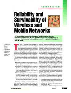
is proportional to @. For a large number of nodes this implies too much traffic on the ring. Especially for real time applications the resulting transfer delay is unacceptable. The token ring access protocol can not use the redundant paths of this topology. Any change of network size or location, like addition and removal of nodes, cause extensive network reconfiguration. Particularly all connections to the backward loops must be renewed. The proposed loop topologies are incongruent with usual architectures. The local or metropolitan area of large computer networks is subdivided into destricts, blocks of buildings, buildings, floors, and offices. The idea is to imitate this structure for the design of large modular local or metropolitan area computer networks. Loop networks are used as components because of their attractive properties. A suitable network architecture primarily connects host computers of some adjoining offices by one loop. For instance all host computers on a floor communicate via a first level loop. Groups of primary loops are interconnected by next higher level loops, e.g. all floor loops of a building are connected by a second level loop and etc. (s. Fig. 1).
F7 Building Ioop . -
A- A A- A
.
-
-
-
-
Floor loops
assumed that all subnetworks use the same kind of loops. Hierarchical loop networks are tree-shaped where nodes of the tree represent loops or host computers. The vertices are ring adapters for attaching hosts or bridges interconnecting subnetworks of different levels. This structure implies simple hierarchical routing. Our reliability analysis in section 2 and the performance study of section 3 compares this improved hierarchical network architecture with individual loop topologies. For ease of modeling we assume that all hosts are connected to first level loops. Users may prefer to attach their highest function servers, for instance large hosts, to a higher level subnetwork. This implies even better reliability and performance for the proposed topology. 2. RELIABILITY OF INDIVIDUAL NETWORKS
HIERARCHICAL LOOP
The unidirectional loop topology has some inconveniences. The most important is its poor reliability, since any link or node (interface) failure disconnects the network [5]. It tolerates not a single fault. Another disadvantage, in terms of reliability is its serial structure whose unreliabiliy increases exponentially with the number of traversed links [2,4]. Each time a node sends a message to another node via an unidirectional loop network, the message must pass through all intermediate nodes and cross the connecting communication links before reaching its destination. When only one involved link or node fails the transmission is impossible. Several solutions have been divised to these points. Basically, they all double the number of links in the network, so that each node is connected to two others. The topologies become complex and suffer from inflexibility. For example, implementation, extension, and maintenance of the proposed FLBH-networks and even routing cause great problems [10,11]. This seems to be a high price for some fault tolerance and improved performance. Hence, a better solution requires modular design to achieve also flexibility and maintainability. The following reliability analysis is based on two complementary reliability indices: terminal pair reliability and fault tolerance. A star network for instance has small diameter, i.e. 2, which implies high terminal pair reliability. But it is fault intolerant because a failure of the central node cuts all connections of the network.
G? Building loop _ .
Hostcomputers
Fig. 1: 3-level hierarchical loop network Individual loops of such a multi-level network architecture are called subnetworks. They may consist of single or double loop networks to fulfil a wide range of requirements on reliability and performance. Depending on the proposed fault tolerance subnetworks are interconnected by one or more bridges. As a bridge connects two subnetworks it is attached to a lower and a higher level loop by a pair of ring adapters. They pass messages to the next adapter on the same ring in case of intra subnetwork traffic. When a message must leave the ring for its destination then it crosses over the two ring adapters of a bridge from the current to the alternate loop (inter subnetwork traffic). The proposed hierarchical loop network architecture has the following attractive features: modularity, expandability, adaptability, flexibility, concurrency, and short path length. Characteristics of some individual loop topologies are summarized in Table 1. Then optimal topologies for hierarchical loop networks are derived which minimize the network diameter for a fixed number of stations. It is
2.1. DIAMETER AND TERMINAL PAIR RELIABILITY
The maximum internode distance, often referred to as the diameter of the interconnection network, places a lower bound on the delay required to propagate information through the network. It is simply the maximum number of communication links that must be traversed to transmit a message to any node along a shortest path. The probability that a point-to-point connection is avai-
8B.3.2 1090
VS.
lable serves as an essential measure for network reliability. The diameter D together with the probability p of link and node (interface)failure defines a lower bound on this terminal pair (two terminal) reliability R, i.e Rs(l-p)D. (For exact reliability computation see for instance [4,7l.) It is clear that a bypass mechanism may reduce the failure probability p but is no solution to the structural reliability problem represented by the exponent D [14-16]:
S
N = C n i i=l In this case the entire hierarchical network can be defined by an s-tuple (n1,n2,...,ns). Any diameter di depends on ni as shown in Table l.So the number of subnetwork interfaces nopt for minimal D and fixed N can be deduced from Eq. 2.1. and Eq. 2.2 as the solution of an extreme value problem. A hierarchical loop network is called homogeneous if it consists of loop subnetworks from the same class. For homogeneous hierarchical loop networks the following equation holds
for all i with l&s and (2.4) ns = cnopt where the coefficient c depends on the topology. Table 2: Characteristics of optimal hierarchical loop networks Class
-
Fig. 2: 16 node individual optimal FLBH loop
unidirectional
Table 1: Diameter of individual loops [1,6,10,17] (As in programming languages int(N) denotes the greatest integer smaller or equal to N) unidir. bidir.
daisychain
opt. FLBH
I@I 1 2
I
I
I
I I
I
I
I
I
I
I
I
cho. ring
The diameter D of a hierarchical loop network depends on the diameters of the individual loops and on the number s of network levels. In the following it is assumed that all loop subnetworks on the same level i have identical diameter di. A message passes the maximum number D of interfaces when il goes through all network levels up to the top level and then down again to a subnetwork of the lowest level (see Figure 1). Hence, the diameter D of a hierarchical loop network is given by s-1
D = ds + 2 C d i P.1) i=l The described topology contains no redundant paths between different network levels. N terminal devices communicate via a hierarchical loop network with subnetworks of ni+l nodes at level i. Notice that the additional node representing a bridge interface connects the subnetwork to the next higher level loop so that
Diameter
"opt
2S@
1
I
I
2s(2s @4-1)+1 chordalting
@ 4
4
If nopt lies between two integers use that one which re-
sults in smaller diameter D. While Table 1 shows that the parameter of optimal double-loop architectures depends on the square root of N, Table 2 indicates the essential advantage of optimal s-level hierarchical loop topologies, i.e. diameter grows only with root s of N. Moreover, the comparison of Table 1 and 2 implies the following result: For large N, optimal hierarchical networks with unidirectional loops and sr3 have smaller diameter than optimal FLBH networks. Minimisation of D with respect to s results in the following optimal level number (2.5) sopt = ln(N/2). The following Figure 2 illustrates the expressions of Tables 1 and 2. Both axis are divided logarithmically which reveals the dramatic reduction of the diameter
8B.3.3 1091
from individual to hierarchical loop architectures. For all hierarchies we used the value of s from Eq. 2.5. When the number of network levels approaches the optimum then small diameter competes with additional cost for bridges. Thus in practice, s should be less than or equal to its optimum value in Eq. 2.5 but great enough to guarantee small diameter. If some host computers are connected to higher level subnetworks results are nearly identical with the expressions summarized in Figure 2.
t
''.
'
10
k-1 j=l stations. Furthermore the main part of the network still connects k Nn,
n
j=1
stations. Together there are still
communication links available. For instance when a first level subnetwork fails all stations not attached to this failed loop can communicate with each other. In this case (N-nl)(N-n1-1)/2 different terminal pairs are still connected. The failure of the highest level loop subdivides the whole network into ns operational subnetworks which preserve N((N/ns)-l)/2 connections. An example of this fault-tolerance and graceful degradation is given by the following table.
1
1W
1oW
1WM)
loow0
Number of attached stations Fig. 3: Diameter of individual and multi-level loop networks 2.2 FAULT TOLERANCE In a network with N attached stations the number of different two party connections equals
I;[
In an unidirectional loop topology a single interface failure disconnects all stations, while in a bidirectional loop network only the failed station is disconnected, i.e.
[N 1 il
connections remain operational. Even in the presence of multiple faults double loop topologies provide degraded service, i.e. communication is still possible among a subset of all stations. Assume that in a hierarchical network with unidirectional loops a single subnetwork failure occurs at level k which may result from one or more interface failures in this loop. Then there remain nk distinguished subnetworks. Each connects
1092
Table 3: Example for the fault-tolerance and graceful degradation of a 3-level hierarchical loop network (5,510) with 250 nodes and 31125 point-to-point connections. fault location 1. level 2.level 3. level
~
1 number of connections
I Yo
29890 25250 3000
196 I81
I I
I
19
Dividing the number of surviving connections by the number of all terminal pairs yields a ratio for service degradation caused by a fault. This quantity can be viewed as a measure for fault isolation ability. A value near one means a high degree of interconnection and only a small degradation which increases when the ratio decreases to zero. For optimal unidirectional hierarchical loop architectures the computed value tends to one for large N and small k compared to s. Hence, faults in low level subnetworks are of minor interest. But for failures in high level loops the immense degradation becomes a problem which can be solved with bidirectional or FLBH loops at high levels. In this section 2 we discussed the fault tolerance of hierarchical loop networks. It was shown that the diameter of this architecture using uni-, bidirectional or Daisy-Chain-loopsincreases only proportional to the root s of N resp. to the root 2s for FLBH-subnetworks (The same applies to the mean internode distance.). This means a drastical reduction of path length and therefore a reliability improvement compared with individual loop networks. How this path length reduction effects the
network performance will be discussed in the following section.
3. PERFORMANCE EVALUATION In addition to short path lengths the subdivision into subnetworks promises increased performance. As the subnetworks are independent several messages can be transmitted concurrently with respect to the whole network and in many cases messages will not interfere. As a consequence, accelerated communication is expected.
3.1 OPERATION In contrast to the diameter, the mean internode distance is the expected number of link traversals a typical message needs to reach its destination. The mean intemode distance is a better indicator of the average message delay than the network diameter, but it too fails to completely capture the relative communication capacity of different loop networks. Unlike the network diameter, the mean internode distance depends on the message routing distribution. This routing distribution specifies the probability that different network nodes exchange messages, and it ultimately depends on the communication requirements of the application and system programs as well as on the mapping of these programs onto the network. In the following, we consider two different message routing distributions. We assume that the probability of node i sending a message to node j is the same for all i and j, i#j. This uniform routing distribution is appealing because it makes no assumption about the type of computation generating the messages. Because most computations should exhibit some measure of communication locality, it provides an upper bound on the mean internode message distance [ll]. The other routing distribution, called local, expects that a node sends more messages to other nodes inside its subnetwork than to nodes outside. LAN performance depends strongly on the medium access protocol. For loop topologies the token and the slotted ring method are used. The buffer insertion ring combines their positive properties. The conflict between data ready to be transmitted by a station and the data stream already flowing on the ring is resolved by dynamically inserting sufficient buffer space into the ring. The buffers are provided by the ring adapters of the attached stations. When a particular station has a message waiting for transmission in its transmit buffer, transmission starts depending on its operational mode (see below). While a station is transmitting its own messages, all data arriving from upstream stations, but not destined to the station itself, are stored in the insertion buffer. Any interface delays all received data for a time sufficiently long to decode their destination addresses (latency). Those messages destined for the station considered are put
into the receive buffer. All others pass immediately (cut through [8])or are written into the insertion buffer if they meet a busy link or a message with higher prioriiy. As long as the station is not transmitting its own data, the contents of the insertion buffer is transmitted to the next station downstream. With regard to the point of time when a station is allowed to transmit a pending message of its own, two operational modes can be distinguished, called station and ring priority [3]. In the first case, a station with a pending transmit request is allowed to send its data immediately if no transit message is being sent from the insertion buffer. Otherwise, it must defer its transmission until the end of the transit message currently being transmitted. This priority rule can be applied only as long as there is no risk of insertion buffer overflow; otherwise, transit traffic on the ring must be prioriiized. In this situation a station is allowed to transmit data of its own only if the insertion buffer is empty. Hence, the insertion buffer will never overflow, provided it can hold a maximum-sizeframe. Intra loop traffic is effected by bridges in the same way as by attached hosts. Inter loop traffic has to cross over both adapters which attach the bridge both of the connected networks. For a bridge the transmit buffer of one adapter is identical with the receive buffer of the other one. So time for crossing over from one loop to the other is similar to the time for starting a transmission from an attached station and depends on the priority rule and the load of the network.
3.2 ANALYSIS Bux and Schlatter studied the simple buffer insertion ring in [3] and observed that the priority rule has no impact on the mean transmission time of messages. Raghavendra and Silvester presented results for buffer insertion rings with FCFS queueing in [ll]. In this section we follow their performance analysis using the following assumptions: 1) The input processes from all stations are Poisson. 2) The message lengths for all stations follow the same distribution. 3) The latency th of a ring adapter is constant and includes the propagation delay for the signals transmitted between neighbouring nodes. 4) All links have identicalcapacity k. 5) Station prioriiy is assumed. 6) Interarrival times between messages on the ring follow a negative exponential distribution. Real network traffic can only approximate the last assumption because the time between two messages on the ring is at least th (header processing time). This follows from the operation described in the previous section but must be neglected for the reason of mathematical tractability. Together with 1) the assumption 6) im-
1093
plies an M/G/1 queue at each node. Let to denote the remaining transmission time at message arrival epoChes. Further let ri be the utilization of interface i. Then the mean delay of a message at the sending station is given by td(1-ri). (3.11 Assume that the message lengths for all stations follow an exponential distribution (M/M/l queue) and that tm is the mean transmit time of messages. Then to equals tm and the mean message delay at the sending station i is simply given by td(1-ri). (3.2) The mean delay for passing any other interface results from the header length and waiting time caused by the incoming messages from the attached station [ l l ]
values for one level loops with 250 stations as well as those for two and three level hierarchies with 253 (11,23) resp. 250 (5,5,10) hosts are computed from the above expressions. The following usual parameters [3,10-121 were used: - capacity 1 Mbit/sec, - mean message length 1 Kbit (tm=lOOO microsec.), - header length 10 bit (th = 10 microsec.). The following Figure 4 shows the results of the analytical performance evaluation, i.e. the mean transmission time of messages arriving at each station according to a mean interarrival time from 0.24 sec to 1.24 sec. Uniform message routing is assumed.
th + riJ1 (tm-th) + r,i-1td(1-ri). (3.3) Here ri,i-1 denotes the utilizationof station i disregarding the traffic arriving from station i-1 [ l l ] . Summing up the values given by expression 3.2 and 3.3 for an average path through the network yields the mean transmission time w of a message from its source to its destination. Now we assume that message arrival rates are identical for all stations and that every transit message is buffered, so that time tm is needed to pass a node anyway. Then the utilization of an unidirectional loop with n nodes is given by (3.4) ri = agtdv, (3.5) rij-1 = gtm/v, where g denotes the whole network traffic (traffic rate), v the number of directed links and a the mean path length for a message [ l l ] . In a hierarchy of loop networks nodes at different levels may be subject to different utilization. This depends on which portion of messages is transmitted via which level. In case of low network traffic the following equation holds for mean transfer delay w w = tm + (a-l)th, (3.6) because the messages do not interfere [lo]. When network traffic increases, data must be buffered in any visited loop interface which results in w = a(tm+th). (3.7) The reduction of mean internode distance as a consequence of the hierarchical tree structure implies a much shorter mean transmission time. According to the above equations this is illustratedby an example in Fig. 4. 3.3 RESULTS For s-level hierarchies of unidirectional loop networks wus denotes the mean transfer delay in milliseconds (wbs is the same for bidirectional networks). This is the time from entering the transmit buffer of the sender until the arrival at the destination node. The
:/,
V
e 4.00
'I\
a 3.50
0,50
0,M
0.94
1.24
Mean interarrivaltm ie Fig. 4: Average transfer delays of individual and hierarchical loop networks
As was to be expected, the network delay is reduced with increasing number of levels. For a low or medium network throughput rate the analytical results overestimate the simulative ones by 10-20%. This deviation seems to be tolerable. However, if a more exact performance analysis is required, the following facts should be taken into account: (i) The interarrival time of message frames from previous stations is at least the header processing time. As a consequence, the message arrival process deviates from Poisson with increasing network load rate. (ii) As discussed in section 3.2 expression 3.4 and consequently Eq. 3.3 are only approximately valid. Each link crossing and destination check constitutes a visit to that link or interface. The mean number of visits to a fixed node divided by the number of all messages is
86.3.6 1094
0.64
called its visit ratio. With these values those ,nodes in a network can be located that most limit performance, i.e. bottlenecks (131. An analysis shows that for uniform routing distribution the high level loop of an optimal hierarchical architecture becomes a bottleneck when traffic increases. This can be compensated for by a more powerful high level loop, like a bi- instead of a unidirectional loop. The majority of messages in most LANs is addressed to nodes in the neighbourhood of the sender, e.g. to the next printer or file server. This means that in a hierarchical topology most network traffic remains in low level subnetworks. As these loops are independent from one another and work concurrently many messages are transmitted at the same time. Together with the short mean internode distance this parallelism results in drastical performance improvements. A similar argument holds if servers for users on several basic loops are attached to higher level subnetworks. In a token ring the transmission of a message is completed when the sender removes the data from the ring. Any message moves around the whole loop network. Hence, the performance of a token ring depends strongly on the number of nodes in the network. The improved topology divides the network into subnetworks to reduce the number of nodes on a communication path at least to the same extent as the diameter. As a consequence a token ring will profit even more from a hierarchical structure than a buffer insertion ring. However, the normal token ring protocol is unable to use alternate routes within FLBH loops.
In this case most traffic remains in low level loops which allows for highly parallel processing. This holds for many applications of large, local and metropolitan area networks. REFERENCES
4. CONCLUSiON This paper presents optimal topologies for hierarchical loop networks. Single and double loop subnetworks can be used to achieve any desired degree of reliability and fault-tolerance. Furthermore, performance benefits make this architecture attractive. For instance the following disadvantages of large FLBH networks are omitted: complex interfaces with 3 inputs and 3 outputs, inflexibiliiy, complex routing, unsuitability for token ring access protocol. The introduced type of interconnection scheme can be extended easily. New host computers are added by connecting them via simple interfaces to the basic loops. The proposed topology assimilates to the scenery where it is used. Cable costs are reduced since optimal hierarchical architectures with single-loop subnetworks are more reliable than corresponding individual double-loop topologies. The reduction of mean and maximum internode distance was quantified to demonstrate the reliability and performance improvements achieved by hierarchical structuring. The results of the performance analysis were validated by simulation. Moreover, performance will increase exponentially when host computers communicate more frequently via short distances.
B. Arden, H. Lee, Analysis of Chordal Ring Network, IEEE Trans. Computers C-30,4, 1981, 291-295. R. Barlow, F. Proschan, StatisticalTheory of Reliability and Live Testing, Holt, Rinehart and Winston, 1975. W. Bux, M. Schlatter, An Approximate Method for the Performance Analysis of Buffer Insertion Rings, IEEE Trans. Commun. COM-31, 1, 1983, 50-55. C.J. Colbourn, The Combinatorics of Network Reliability, Oxford University Press, 1987 M. Fiol, L. Yebra, I. Alegre, M. Valero, A Discrete Optimization Problem in Local Networks and Data Alignment, IEEE Trans. Computers, C-36, 6, 1987. A. Grnarov, L. Kleinrock, M. Gerla, A Highly Reliable, Distributed Loop Network Architecture, Proc. 10th Fault-Tolerant Computing Symp., 1980, 319-322. K.D. Heidtmann, Smaller Sums of Disjoint Products by Subproduct Inversion, IEEE Trans. Reliability, R38,3,1989,305-311. P. Kermani, L. Kleinrock, Virtual Cut Trough: A New Computer Communication Switching Technique, Computer Networks 3, 1979,267-286. M. Liu, Design of the Distributed Double-Loop Computer Network (DDLCN), J. Digital Systems 5, 1981, 3-37. [lo] C. Raghavendra, M. Gerla, A. Avizienis, Reliable Loop Topologies for Large Local Computer Networks, IEEE Trans. Computers C-34, 1, 1985, 46-54. [11]C. Raghavendra, J. Silvester, A Survey of MultiConnected Loop Topologies for Local Computer Networks, Comp. Networks and ISDN Systems 11, 1986, 29-42. [12]C. Raghavendra, J. Silvester, Double Loop Network Architectures - A Performance Study, IEEE Trans. Commun. COM-33,2, 1985, 185-187. [13]D. Reed, D. Grunwald, The Performance of Multicomputer Interconnection Networks, IEEE Computer 20, 6, 1987, 63-73. [14]J. Saltzer, K. Pogran, D. Clark, Why a Ring?, Computer Networks 7, 1983,223-231. [15]J. Saltzer, K. Pogran, A Star-Shaped Ring Network with high Maintainability, Computer Networks 4, 1980,239-244. [l6] W. Stallings, Local Networks, ACM Computing Surveys 16,1,1984,4-41. [17]J. Wolf, M. Liu, B. Weide, D. Tsay, Design of a Distributed Fault-Tolerant Loop Network, Proc. 9th Fauft-Tolerant Computing Symp., 1979, 17-24.
8B.3.7 1095