Progress In Electromagnetics Research C, Vol. 33, 95–108, 2012
REMARKS ON THE MEASUREMENT OF STATIC PERMITTIVITY THROUGH A CLASSICAL DESCRIPTION
B. Tellini1, * and M. Bologna2 1 Department
of Energy and Systems Engineering, University of Pisa, Largo L. Lazzarino, Pisa I-56122, Italy 2 Instituto
de Alta Investigaci´on IAI, Universidad de Tarapac´ a, Casilla 7-D, Arica, Chile Abstract—In this paper, the concept of static electric permittivity and its measurement are discussed. A classical description of polarization via a harmonically bound charge model is revisited and the evolution of the polarization concept in the presence of free electrons is shown. Various electrostatic problems are defined under ideal conditions. The measurement procedures for characterizing the static permittivity of dielectrics and conductors via the measurement of induction-electric field, charge-potential difference and electrostatic energy variation are discussed. Two basic experiments with a lossy dielectric are described. In one case we reach an electrostatic equilibrium with an indeterminate solution. In the other case we define a magnetostatic problem. Finally, we comment on the case of a laboratory experiment remarking on the proper use of the lowfrequency limit of dielectric constant and showing experimental results performed on a supercapacitor. 1. INTRODUCTION Electric permittivity ε is a constitutive parameter relating the macroscopic fields induction D and electric field E. The assumption that D depends only on E holds for constant fields, while for variable fields a relationship between D and H is possible. Such an effect remains on the order of a/λ, where a is the atomic dimension and λ is the field wavelength [1]. This effect is generally negligible, especially in slowly varying fields. Received 16 June 2012, Accepted 18 September 2012, Scheduled 1 October 2012 * Corresponding author: Bernardo Tellini (
[email protected]).
96
Tellini and Bologna
Under the hypothesis of linearity, D and E generally show a frequency dispersion relationship. This means that ε varies as a function of the angular frequency ω and D(ω) = ε(ω)E(ω). In the time representation, D(t) and E(t) are not instantaneously related. The field D(t) depends on the history of the electric field [1, 2], i.e., it holds the convolution integral relationship ½ ¾ Z +∞ D(t) = ε0 E(t) + G(τ )E(t − τ )dτ (1) −∞
where the kernel G(τ ) depends on the structure of the dielectric material. In more detail, G(τ ) is the inverse Fourier transform of the electric susceptibility χ(ω) = ε(ω)/ε0 − 1. A full description of the physics of dispersion in dielectric media remains, in general, a very complex task and it should involve the study of electron and ion motion through a combined use of classical and quantum mechanic theory. However, a simple model of harmonically bound charges (electrons and ions) is generally adopted to illustrate this phenomenon. In terms of classical models of the molecular properties, the relationship between the macroscopically defined parameter ε and the molecular properties can be summarized by the Clausius-Mossotti’s equation: γ=
3 ε/ε0 − 1 N ε/ε0 + 2
(2)
that relates the molecular polarizability γ to ε and Nγ (3) 1 1 − Nγ 3 where N is the average number of molecules per unit volume. In 1929 Debye presented a model for the response of electric dipoles to an alternating electric field [3, 4]. The model showed an exponential relaxation of dipole polarization and this led to the known expression ε(0) − ε(∞) ε(ω) = ε(∞) + (4) 1 + iωτ where τ is the relaxation time, ω the angular frequency of the alternating electric field, and ε(0) and ε(∞) are the zero- and highfrequency limits. A simple physical consideration shows that when ω → ∞, the function ε(ω) → ε(∞), i.e., ε0 . Indeed, for a valid macroscopic description the condition ω ¿ c/a must hold. Since λ ≈ c/ω, as the frequency increases λ becomes comparable with the atomic dimension a. This is clearly discussed in [1]. χ=
Progress In Electromagnetics Research C, Vol. 33, 2012
97
Development of the Debye model and further investigation of the relaxation response were a consequence of the possibility of applying the dielectric spectroscopy over an extremely broad frequency range. Today it is possible to measure from µHz to tens of GHz with the use of commercially available spectrometers. Measurements at low frequency, f ≤ 2 GHz, are generally performed through the use of dielectric samples prepared in parallel-plate geometry [5]. At higher frequencies reflectrometric techniques with a sample mounted at the end of the transmission lines and analysis of transmission properties are adopted [6, 7]. Note that time domain and frequency domain measurement techniques are generally used to characterize the dielectrics in the µHz-MHz frequency range. Reflective coaxial, transmission coaxial and quasi-optical methods are used to cover the range 108 –1011 Hz, while higher frequency ranges from 1011 –1015 Hz are covered by Fourier-transform methods [8–10]. In the very high frequency range, ε(ω) is generally expressed as ¡ ¢ ε(ω) = ε0 1 − 4πN e2 /mω 2 . Recently, the authors developed various experimental and theoretical studies in the field of metamaterials, mainly focusing on the magnetic permeability of resonant repeated structures at industrial frequencies [11–13] and on the characterization and modeling of supercapacitor [14]. Such studies showed some conceptual and practical problems for the characterization of materials with permittivity or permeability dispersion at low frequencies. With reference to the study developed in [14] on a supercapacitor, an evident dispersion of the equivalent capacitance was observed down to 1 mHz. In such a sense, some remarks can be made concerning the definition of ε in the case of static fields. With reference to the Debye formula we revisit the meaning and measurement of ε at zero frequency [15] ε(0) = lim ε(ω). ω→0
(5)
Referring to non-variable fields, in principle we can distinguish between constant field configurations with and without motion of charges. For clarity, the steady-state condition is characterized in the first case by a direct motion of charges, thus it is defined as a magnetostatic problem. In the second case there is no charge motion after the transient phase is extinguished, resulting in an electrostatic problem. In [1] and [2] the determination of the field due to a static point charge at a specific distance from a boundary plane between two different dielectric media 1 and 2 is analyzed. The analysis shows that for ε2 À ε1 medium 2 behaves much more like a conductor than a dielectric. In the limit case of ε2 → ∞ the solution leads
98
Tellini and Bologna
to the same results obtained by the method of images for a conductor in place of medium 2. This suggests the same result, ε = ∞, for lossy dielectrics in the presence of constant fields. In fact, a dielectric medium with zero electrical conductivity, σ = 0, is an ideal assumption, while in practice all the dielectric materials exhibit a σ different from 0. As a consequence, once any transient phase is extinguished the dielectric materials behave like a conductor under non-variable fields. In particular, we show how a lossy capacitor connected to a direct current generator defines a magnetostatic problem, and how the relationship V /I = R, with V the potential difference I the current and R the resistance of the dielectric, is representative of the steady state condition, providing ε → ∞ the same as for a conductor. This paper is organized as follows: In Section 2, we readdress the theory of polarization through a classical description based on a harmonically bound charge model, and we discuss how ε → ∞ in the limit of a static field if unbounded electrons are present in the medium. In Section 3, we define various electrostatic problems and we show how to estimate ε for a conductor via the measurement of, induction-electric field D-E, charge-potential difference Q-V and through an energy analysis. In Section 4, we discuss an electrostatic and a magnetostatic problem corresponding to actual measurement conditions and we comment on the measurement of permittivity in a practical case. 2. CLASSICAL MODEL OF POLARIZATION For the sake of clarity we shall consider a short review of a simple model of fields in the matter based on Eq. (1) [1, 2, 16]. Specifically, we neglect the difference between the applied electric field and the field in the matter and assume that they are uniform. The model is therefore appropriate only for substances of relatively low density. The equation of motion for an electron of charge e bound by a harmonic force and under the influence of an electric field E(t) is £ ¤ ¨ + γ x˙ + ω02 x = −eE(t) m x (6) where γ is the phenomenological friction constant of the damping force. Considering the dipole moment contributed by one electron, p = −ex, and passing to the Fourier representation we obtain p=
¤−1 e2 £ 2 ˆ ω0 − ω 2 − ıωγ E(ω). m
(7)
Progress In Electromagnetics Research C, Vol. 33, 2012
99
If we suppose that there are N/V molecules per unit volume with Z electrons per molecule, then we may write ¤−1 N Ze2 £ 2 ˆ = ε0 χE(ω) ˆ ˆ ω0 − ω 2 − ıωγ P = E(ω). V m We deduce that the dielectric constant is ¤−1 N Ze2 £ 2 εˆ =1+ ω0 − ω 2 − ıωγ . ε0 V mε0 We assume that the electric field is in the form of E(t) = E0 cos[ωc t]
(8)
(9)
(10)
so as to obtain the case of a constant and uniform electric field taking the limit ωc → 0. Going back to the time representation, from Eq. (8) we obtain ¡ ¢ e2 N Z ω02 − ωc2 E0 cos[ωc t] e2 N Zγωc E0 sin[ωc t] h h P= ¡ 2 ¢2 i + ¡ ¢2 i . (11) 2πmV γ 2 ωc2 + ω0 − ωc2 2πmV γ 2 ωc2 + ω02 − ωc2 From Eq. (11), for ωc → 0, the vector P is P=
e2 N Z E0 ≡ ε0 χE0 . 2πmVω02
(12)
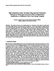
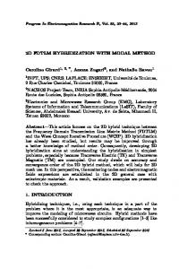
Note that ω0 → 0 means that the electrons are somewhat free and the medium approaches the condition of a conductor in the static case. As expected, ε → ∞. 3. ELECTROSTATIC PROBLEM — IDEAL CONDITIONS Let us imagine a charged ideal parallel-plate capacitor as that shown in Fig. 1. If the charge density is σ, the electric field inside the capacitor is uniform and its magnitude is E = σ. Now consider an indefinite slab of a non-charged conductor and put it into the capacitor as shown in Fig. 2. Assuming the thickness of the conductor is small when compared with the other dimensions, we can deduce that, by induction, the two surfaces will be opposite the charge of the capacitor. This configuration has the following electrical field distribution in the three regions VI , VII , VIII ˆ E = 0, E = σ k ˆ EI = σ k, II III
100
Tellini and Bologna
Figure 1. Charged ideal parallel-plate capacitor. Absolute vacuum is between the electrodes. The terms V0 and h stand for the per unit area volume and separation distance between the electrodes.
Figure 2. Charged ideal parallel-plate capacitor with a conducting slab inserted into it. Absolute vacuum is between the electrodes and the slab. The terms VI , VII , and VIII stand for the volume per unit area between the upper electrode and the slab, of the slab and between the lower electrode and the slab. ˆ is the unit vector normal to the capacitor plates. Since the where k conductor did not carry any charge, the correspondent induction vector D is continuous DI = DII = DIII . In region II the field is in a medium and it holds the relationship DII = ˆ Since E = 0, εEII while in the other regions we have DI = DIII = σ k. II the continuity of the field D is preserved if ε → ∞. The same result is obtained approaching the estimation of ε via the measurement of the integral quantities Q and V . With reference to Fig. 1, the potential difference V0 between the electrodes is V0 = E0 h and the capacitance of the capacitor is C0 = Q/V0 . Inserting the conducting slab into the capacitor as shown in Fig. 2, the potential difference between the electrodes at the steady-state condition is V = VI + VIII = E0 (hI + hIII ) since EII = 0 and VII = 0. The capacitance of the system is C = Q/V and its inverse 1/C = VI /Q + VIII /Q. This is equivalent to a dielectric plate II with infinite permittivity
Progress In Electromagnetics Research C, Vol. 33, 2012
101
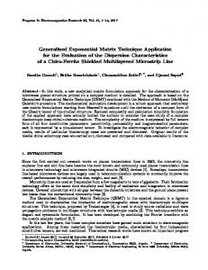
inserted into the capacitor. In such a case, a zero potential difference is maintained between the upper and lower boundary surfaces of the dielectric plate as well as for the conducting slab. 3.1. Electrostatic Configuration: Dielectric Slab Now we consider a further example to better clarify how to define electrostatic properties, such as the dielectric constant, through the analysis of the variation of the electrostatic energy. For this purpose we consider an ideal capacitor with the two plates charged with an electrical charge ±Q0 , surface S, and separated by a distance h, as for Fig. 1. For the sake of simplicity, in this section only we will set ε0 as unit. As previously mentioned, the uniform electric field inside has magnitude E0 = σ0 = Q0 /S. Let us charge a dielectric slab on the two surfaces with charge Q1 . The slab generates a uniform electric field outside the slab Q1 E1 = ± k = ±σ1 k (13) S where the minus sign refers to the semi-space underneath the slab. Inside the slab the electric field vanishes. The electrostatic energy of the system capacitor and dielectric slab shown in Fig. 3 is simply the R sum of the single electrostatic energies given by the formula U = 1 2 V E · DdV, namely 1 1 1 U1 = E02 V0 + E12 Vu + E12 Vd (14) 2 2 2 where V0 = Sh, Vu and Vd are the volumes of the two semi-spaces outside the slab. Inserting the slab into the capacitor as shown in Fig. 4 we have 1 1 1 U2 = (E0 + E1 )2 VI + E02 VII + (E0 − E1 )2 VIII 2 2ε 2 1 2 1 2 + E1 (Vu − VI ) + E1 (Vd − VIII ). (15) 2 2
Figure 3. Charged ideal parallel-plate capacitor and charged dielectric slab.
102
Tellini and Bologna
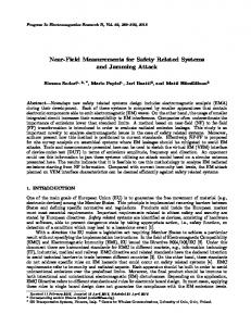
Evaluating the change of the electrostatic energy of the system we have µ ¶ 1 2 1 ∆U = − E0 1 − VII + E1 E0 (VI − VIII ). (16) 2 ε The electrical field is E1 = σ1 = (DI − DII ) · n, where n is the outer-pointing normal from the slab. Measuring the variation of the electrostatic energy we have a measure of the induction vector D. Note that if VIII = VI then ∆U does not depend on the external charge Q1 . Finally, taking the limit for ε → ∞ we rediscover the variation of energy for a conductor 1 ∆U = − E02 VII + E1 E0 (VI − VIII ). (17) 2 3.2. Electrostatic Configuration: Dielectric Sphere Next we study an analogous case considering a dielectric sphere of radius a with a charge distribution on the surface given by σ(θ) = σex cos θ. The function σ(θ) has been selected in such a way as to find a simple analytical solution. Solving the Laplace equation for the potential, ∇2 φ = 0, we obtain for the potential the following σex φin = r cos θ (18) ε+2 ε − 1 E0 a3 cos θ σex a3 cos θ φout = + . (19) ε+2 r2 ε + 2 r2 As before, we imagine inserting the sphere into the capacitor as shown in Fig. 5. The field of the sphere is assumed to vanish at the electrodes. Combining the electric field given by Eqs. (18) and (19) with the well
Figure 4. Charged ideal parallel-plate capacitor with charged dielectric slab inserted into it.
Figure 5. Charged dielectric sphere inserted into an ideal parallel-plate capacitor. Absolute vacuum is between the electrodes and the sphere.
Progress In Electromagnetics Research C, Vol. 33, 2012
103
known solution of a dielectric sphere in a uniform electric field we obtain for the field inside the sphere µ ¶ 3E0 σex ˆ Ein = − k, (20) ε+2 ε+2 ˆ is the unit vector in the z direction. In terms of polar unit where k vector ˆ = cos θˆr − sin θθ. ˆ k Outside of the sphere we have ˆ + EP , Eout = E0 k
(21)
where the components of the vector EP are ε − 1 E0 a3 2a3 σex cos θ cos θ + ε + 2 r3 ε + 2 r3 3 a E0 (ε − 1) sin θ a3 σex sin θ = + . r3 (ε + 2) (ε + 2) r3
EP r = 2
(22)
EP θ
(23)
With respect to the vector D, inside the sphere it holds D = εEin
(24)
while outside the sphere it coincides with the field Eout . The energy variation of the system is Z 2 1 2a3 πσex 1 ∆U = (25) E · DdV − E02 VC − 2 V 2 3(ε + 2) where VC = Sh is the volume enclosed by the capacitor. If a ¿ h we can perform the integration considering a vanishing electrical field outside of the capacitor. We may rewrite Eq. (25) as · ¸ 4π 3 1 2 ∆U = a (ε − 1)E0 − E0 σex . (26) 3(ε + 2) 2 Note that for ε → ∞ the contribution of the external charge, σex , vanishes. The same result is obtained for the case of a charged conducting sphere, although the considered charge distribution is an ideal assumption since a charge on a conducting sphere tends to distribute uniformly. We shall end this section considering a dielectric sphere with a uniform charge distribution on its surface. Using the same notation of the previous example we can write, for the field inside the sphere Ein =
3E0 ˆ k, ε+2
(27)
104
Tellini and Bologna
and for the field outside the sphere ˆ + EP Eout = E0 k 2a3 E0 (ε − 1) cos θ q EP r = + E cos θ + 0 4πr2 r3 (ε + 2) a3 E0 (ε − 1) sin θ EP θ = . r3 (ε + 2) The variation of electrostatic energy is Z 1 1 q 4 ε − 1 E02 ∆U = E · DdV − E02 VC − = πa3 2 V 2 8aπ 3 ε+2 2
(28) (29) (30)
(31)
that is independent from the external charge q. The case of a conductor is obtained evaluating the limit for ε → ∞. 4. ELECTROSTATIC AND MAGNETOSTATIC PROBLEM — ACTUAL CONDITIONS Dielectrics and conductors exhibit different values of the electrical conductivity σ. Such a difference is evident over certain time scales or frequency ranges within which low and high values of σ are more characteristic of an insulating and conducting behavior. On the other hand, it is common for a material to change its behavior showing a proper frequency dispersion law for its parameters. In particular, apart from the absolute vacuum any other material behaves as a conductor in static conditions. This poses some questions on the possibility of measuring the static ε under “actual conditions”, i.e., with a lossy dielectric. Is it possible to reach an electrostatic steady-state or could we reach other conditions from which it would be possible to derive the correct estimation of static ε? Such considerations find an experimental evidence and a practical application with new dielectric materials, such as those for supercapacitors that show a permittivity dispersion at frequency well below 1 Hz [14]. In Table 1, we report some experimental results c performed on a 120 F Maxwell° double layer supercapacitor. The results are expressed in terms of real part of the capacitance of a G (conductance)-C (capacitance) parallel equivalent circuit. The data clearly show a dispersion of the estimated parameter down to 1 mHz. Looking at the capacitance values reported in Table 1, we can notice how they are still far from converging to a constant capacitance value at lower frequencies. This leads to the question on how to measure and to define the static capacitance or, alternatively, on how to properly read the obtained experimental results. The static
Progress In Electromagnetics Research C, Vol. 33, 2012
105
Table 1. Estimated real part of the capacitance value of an equivalent G-C parallel circuit of the supercapacitor. frequency (Hz) 0.001 capacitance (F) 119.29
0.005 104.10
0.01 100.80
0.05 86.30
0.1 63.40
0.5 1 8.10 2.55
capacitance value is usually provided by the manufacturer, but its meaning should be properly taken into account. As written in the introduction, the characterization of static permittivity becomes more critical for materials showing permittivity dispersion at low frequencies. If for example they are used as energy storage devices, it is important to know as accurately as possible the effective stored and suppliable energy. Let us first find the time scale to reach the static condition for lossy dielectrics. For simplicity, imagine inserting an external charge density ρ(x, y, z) inside a lossy dielectric sphere. The continuity equation is written as: ∂ ρ(r, t) + ∇ · J(r, t) = 0. (32) ∂t Using the phenomenological relation J = σE and Maxwell’s equation ∇ · E = ρ/ε we obtain for the charge density ∂ σ ρ(r, t) + ρ(r, t) = 0 ∂t ε
(33)
that has as solution
h σ i ρ(r, t) = ρ(r, 0) exp − t . (34) ε The time constant through which the dynamic system evolves can be estimated via an experimental observation. For example, we can try to measure the field inside the sphere taking into account that for any conductor the charge will finally distribute on the external surface of the body vanishing the electric field inside the material. Using the semi-empirical argument given above, at first approximation, we can assume an exponential decay of the field and we can write the time evolution expression for the charge density as · ¸ t ρ(x, y, z, t) = ρ(x, y, z, 0) exp − , (35) τeff where τeff is τeff =
εeff σ
(36)
106
Tellini and Bologna
and where we can define εeff as the equivalent permittivity better fitting the time evolution for the charge density. However, once electrostatic equilibrium is reached we have defined an indeterminate problem. Both D and E are zero at equilibrium inside the medium. Outside of the sphere D and E are the same field (except for the universal constant ε0 ) and their magnitude at the sphere surface is the superficial charge density. Since the discontinuity of D is the value of the superficial charge density, this implies that inside the sphere the fields vanish. Let us now consider the problem defined in Fig. 6 that consists of a direct current generator connected to a lossy capacitor. The steady-state condition is driven by Ohm’s law V /I = R where V is the potential difference I is the current and R is the resistance of the dielectric. Strictly speaking, we have defined a magnetostatic problem. In principle, from the geometric parameters of the medium, it is possible to estimate the value of σ via the constitutive equation J = σE. On the other hand, we will never reach electrostatic equilibrium. Consequently we are not able to measure the static permittivity. However, as for the previous case of the sphere, we have a conductor behavior that is in agreement with previous sections and we can attribute this to the infinite value of the static ε. Referring still to the problem defined in Fig. 6, let us comment on the case of a common laboratory experiment with low lossy dielectrics. Once the DC generator is closed on the capacitor system a first charge transient of the capacitor follows when the circuit is switched on. For simplicity, we can assume that the charge transient time constant is negligible, for example when compared to τeff . In practice the material would respond to a voltage step input, while the estimated ε would be the value assumed by the permittivity during the “first instances” of the main transient, i.e., for t ¿ τeff . We believe that the present analysis may provide a contribute to the characterization of static permittivity and to possible development of capacitance standards [17–19].
Figure 6. Magnetostatic field problem. Capacitor setup.
Progress In Electromagnetics Research C, Vol. 33, 2012
107
5. CONCLUSIONS In this paper, we discussed the concept and measurement of static electric permittivity. A formal description and measurement definition of such a parameter was provided via a classical model of polarization, as well as an analysis of various electrostatic configurations. Two basic experiments with a lossy dielectric were described. In one case, the charge evolution inside a sphere previously charged by the insertion of an external charge density was treated. Some remarks on the effective time constant were provided. In the other case a magnetostatic problem was defined by supplying a capacitor filled with a lossy dielectric via a DC generator. In this case, it was stressed how the system never reached electrostatic equilibrium. In both cases, after the transient phases were extinguished we observed a conductor behavior. As a consequence, we could attribute to the static ε of the investigated material an infinite value. The case of a common laboratory experiment and experimental results performed on a commercial supercapacitor were also commented on to point out the meaning of the value attributed to ε in actual measurement conditions. The presented analysis may help to discuss the dielectric behavior of actual materials as well as to reassess the concept and measurement of permittivity under static conditions. Finally, this can find practical applications with energy storage devices for which dielectric materials show permittivity dispersion at low frequencies. ACKNOWLEDGMENT MB acknowledges financial support from FONDECYT project No. 1110231. We thank C. Beeker for her editorial contribution. REFERENCES 1. Landau, L. and E. Lifshitz, Electrodynamics of Continuous Media, Pergamon Press, Oxford, 1981. 2. Jackson, J. D., Classical Electrodynamics, John Wiley & Sons, Inc, New York, 1998. 3. Debye, P., Polar Molecules, Chemical Catalogue, New York, 1929. 4. Brooks, J. S., R. Vasic, A. Kismarahardja, E. Steven, T. Tokumoto, P. Schlottmann, and S. Kelly, “Debye relaxation in high magnetic fields,” Physical Review B, Vol. 78, 045205-1–6, 2008. 5. Brand, R., P. Lunkenheimer, and A. Loidl, “Relaxation dynamics in plastic crystals,” Journal of Chem. Phys., Vol. 116, 10386– 10401, 2002.
108
Tellini and Bologna
6. Hasar, U. C. and O. Simsek, “An accurate complex permittivity method for thin dielectric materials,” Progress In Electromagnetics Research, Vol. 91, 123–138, 2009. 7. Hasar, U. C., “Permittivity measurement of thin dielectric materials from reflection-only measurements using one-port vector network analyzers,” Progress In Electromagnetics Research, Vol. 95, 365–380, 2009. 8. Chen, L., V. V. Varadan, C. K. Ong, and C. P. Neo, Microwave Theory and Techniques for Materials Characterization, Wiley, 2004. 9. Barsoukov, E. and M. J. Ross, Impedance Spectroscopy Theory, Experiment, and Applications, Wiley, 2005. 10. Lunkenheimer, P., A. Pimenov, B. Schiener, R. Boemer, and A. Loidl, “High-frequency dielectric spectroscopy on glycerol,” Europhysics Letters, Vol. 33, 611–616, 2007. 11. Tellini, B., M. Bologna, and A. Petri, “Measurement of magnetism in composite materials,” IEEE Trans. Instrum. Meas., Vol. 58, 3411–3417, 2009. 12. Bologna, M., A. Petri, C. Zappacosta, and B. Tellini, “Effective magnetic permeability measurement in composite resonator structures,” IEEE Trans. Instrum. Meas., Vol. 59, 1200–1206, 2010. 13. Tellini, B. and M. Bologna, “Magnetic composite materials and arbitrary B-H relationships,” IEEE Trans. Magn., Vol. 46, 3967– 3972, 2010. 14. Barsali, S., M. Ceraolo, and B. Tellini, “Frequency dependent parameter model of supercapacitor,” Measurement, Vol. 43, 1683– 1688, 2010. 15. Kaatze, U., “Techniques for measuring the microwave dielectric properties of materials,” Metrologia, Vol. 47, 91–113, 2010. 16. Greffe, J. L. and C. Grosse, “Static permittivity of emulsions,” Progress In Electromagnetics Research, Vol. 06, 41–100, 1992. 17. Gregory, A. P. and R. N. Clarke, “Traceable measurements of the static permittivity of dielectric reference liquids over the temperature range 5–50◦ C,” Meas. Sci. Technol., Vol. 16, 1506– 1516, 2005. 18. Wang, Y., “Frequency dependence of capacitance standard,” Rev. Sci. Instrum., Vol. 74, 4212–4215, 2003. 19. Keller, M. W., A. L. Eichenberger, J. M. Martinis, and N. M. Zimmerman, “A capacitance standard based on counting electrons,” Science, Vol. 285, 1706–1709, 1999.