1
Remediation of soils polluted with 2,4-D by electrokinetic soil flushing with facing
2
rows of electrodes: A case study in a pilot plant
3 4 5 6 7 8 9 10 11 12 13
C. Riscoa, R. López-Vizcaínoa, C. Sáezc*, A. Yustresb, P. Cañizaresc, V. Navarrob, M.A. Rodrigoc
14
Abstract
15
This study focuses on evaluating the application of electrokinetic soil flushing (EKSF)
16
technologies to remediate soil polluted with 2,4-dichlorophenoxyacetic acid (2,4-D). This
17
compound was selected as an example of polar herbicides that may cause soil percolation
18
and groundwater contamination due to its high water solubility, lifetime and mobility. To
19
evaluate this technology, a 40-day test was conducted on a bench-scale set-up (175 dm3
20
of capacity) that was fully automated and operating under potentiostatic mode (1 V cm-
21
1
22
electrolyte wells were monitored daily, and at the end of the tests, a post-analysis
23
characterization of the soil section was performed to obtain 3-D plots of the changes in
24
each parameter. Simultaneously, a blank test was carried out (without applying an electric
25
field) to determine spreading of the pollutant in the soil that did not experience an electric
26
field. The results indicate that the 2,4-D is transported to the anode wells by
27
electromigration (the primary species is an anion under the treatment pH) and the cathode
28
wells by electroosmotic drag, even though a lower concentration is obtained because a
29
large volume of water is mobilized. After 40 days of the EKSF treatment, 50 % of the
a
Department of Chemical Engineering, Institute of Chemical & Environmental Technologies, University of Castilla-La Mancha, Campus Universitario s/n, 13071 Ciudad Real, Spain b Geoenvironmental Group, Civil Engineering School, University of Castilla-La Mancha, Avda. Camilo José Cela s/n, 13071 Ciudad Real, Spain c Department of Chemical Engineering, Faculty of Chemical Sciences&Technologies, University of Castilla-La Mancha, Campus Universitario s/n, 13071 Ciudad Real, Spain
). The electrical current, temperature, pH, humidity and pollutant concentration in the
1
initial 2,4-D leaked into the soil was eliminated, 25% remained in the soil, and the
2
remaining 25 % was volatilized.
3 4 5
Keywords: 2,4-D, herbicide, electroremediation, natural soil, pilot plant
6
*Corresponding author:
[email protected]
7
Tel.: +34 902204100 ext. 6708; fax: +34 926295256.
8 9
1
1.
INTRODUCTION
2 3
Pesticide remediation is a primary concern of the scientific community because of its high
4
risks to human health and the environment [1, 2]. 2,4-Dichlorophenoxyacetic acid (2,4-
5
D) is a chlorinated phenoxy herbicide with a high water-solubility, lifetime and mobility,
6
whose continuous use to prevent weeds may cause soil percolation and groundwater
7
contamination [3]. Furthermore, the bio-refractory character of chlorophenoxy herbicides
8
inhibits their efficient removal from soil and requires the development of new treatment
9
technologies to eliminate these pesticides from contaminated soil [4].
10 11
In this field, due to its operational flexibility, the electrokinetic soil remediation (EKSR)
12
of soil is possibly the most feasible alternative used for the recovery of contaminants in
13
low-permeability soils among the in situ techniques. Electrokinetic processing of soil
14
involves the application of a low-density direct current through a wet-soil mass, which
15
results in the development of electrical, hydraulic, and chemical gradients. Thus, an
16
electric field is created by inserting electrodes into the contaminated site and passing the
17
current through it, which makes the contaminant particles mobile in the soil media [5] by
18
means of different electrokinetic processes (electroosmosis, electromigration and
19
electrophoresis among them). The EKSR has been widely tested for a wide range of
20
contaminants, including emerging organic pollutants [6-8], hydrocarbons [9-12] and
21
heavy metals [13, 14]. In fact, the removal of pesticides using EKSR has become a hot
22
topic [4, 6, 7, 11, 15]. Gomes et al. 2012 [15] and Rodrigo et al., 2014 [4] reviewed the
23
experimental works carried out in organochlorines and pesticide soil electroremediation,
24
paying attention not only to the efficiency of EKSF but also to the integration of this
25
technique with other remediation technologies such as bioremediation, permeable
1
reactive barriers (PRB), phytoremediation… These two review-works concluded that
2
further research is needed and a number of technical and environmental issues will require
3
extra evaluation for full-scale application. In general, removal efficiencies reported in
4
actual contaminates soils are much lower than the ones obtained with spiked kaolinite
5
(commonly used as model of low permeable soil in many works), showing the influence
6
of other factors (as well as electrode arrangements, flushing fluid, electric filed.) like
7
aging of the contamination and adsorption to soil particles. Besides this, the loss of the
8
pesticides by filtration, dragging of superficial water or evaporation have not been clearly
9
stated and these are important points to be capable to control the diffusion of pesticides
10
into the soil [6, 7, 16, 17]. Regarding the herbicide tested in this work (2,4-D), its
11
degradation in liquid phase has been widely studied[18-24], but at the knowledge of these
12
authors there are only two works [16, 25] based on the remediation of soil polluted with
13
2,4-D. Jackman et al. 2001 [16] studied the electrokinetic movement of 2,4-D through
14
soil and its in situ biodegradation, obtaining more than 80 % of efficiency. On the other
15
hand, Ma et al 2010 [25] tested the simultaneous removal of 2,4-dichlorophenol and Cd
16
by combining electrokinetic soil flushing and adsorption. Results obtained corroborated
17
the promising potential of in situ electroremediation of soils co-contaminated with
18
organics and heavy metals, with irrelevant changes in soil pH values.
19 20
All of these cited studies have contributed to increasing the knowledge on the
21
fundamentals of electrokinetic processes. Generally, they are assessed in a laboratory or,
22
in certain cases, a bench [26-31] scale using a hermetic column in which the electrodes
23
are situated in independent chambers of the soil electro-remediation reactor. However, in
24
actual applications, the electrokinetic reactor is expected to be an open system in which
25
both electrolyte wells (where electrodes are placed) and the soil are in direct contact with
1
the atmosphere. Unfortunately, few applications have been assessed on a large-scale open
2
reactor. Kim et al. (2012)[29] evaluated the influence of electrode configuration on the
3
electro-remediation of a multi-metal contaminated soil in a pilot-scale field application.
4
In addition to a relevant heating of the soil, they observed that the groundwater flow,
5
gravitational force, and electroosmotic flow were combined together and had a complex
6
effect on the transport of the mobilized contaminants. Lee et al. (2011) [28] also carried
7
out a long term study for the electrokinetic remediation of nitrate from greenhouse soil
8
on
9
They observed the relevant influence of the electrode arrangement on the magnitude of
10
both electromigration and electroosmotic fluxes. Similarly, Lopez-Vizcaíno et al. [32, 33]
11
studied the scaling up of the EKSR for soils contaminated with phenanthrene and
12
discovered important discrepancies between the lab, bench and pilot scales. In fact, it was
13
observed that in the large scale, there were several processes controlled by non-
14
electrochemical mechanisms that were significant (and were not observed on the
15
laboratory scale). Even in the case of the low-permeability soil, gravity and the
16
evaporation fluxes were more relevant than the electrokinetic fluxes. Moreover, a large
17
operation time and energy consumption were required for the decontamination of the
18
phenantrene-polluted soils. In light of these observations, further studies are required for
19
an appropriate scale-up of the process and to clarify the controlled mechanism of the
20
remediation process as well as the influence of the electrode location, composition and
21
flux of the flushing fluids and electric field on the efficiency of the electro-remediation
22
process.
23
Hence, soil electroremediation consists of the addition of numerous processes with
24
different typologies such as transport, reactive, physical and equilibrium processes. All
25
of them have very different rates and the size of the experimental system in which they
a
pilot-scale
and
using
a
specially
designed
electrode
module.
1
are studied is critical, in order to reach a clear understanding of the complex interactions
2
between these processes. Although most of the works published in the literature attains a
3
very good understanding of each of these processes separately (and even of the
4
combination of two or three of them) in order to fully understand the interactions and in
5
order to be able to extrapolate to a full-scale application it is required at least the
6
experimentation in plants larger than the typical lab-scale plants used. Thus, the goal of
7
this study has been to evaluate the application of electrokinetic soil flushing technologies
8
(EKSF) for the remediation of soil polluted with 2,4-D, which is selected as an example
9
of an herbicide. In the first stage, the dissemination of the pollutant in the soil is studied
10
after a simulated spill incident; attention is given to the distribution of the pollutant in the
11
soil matrix and the transfer of the pollutant to the liquid and gas phases. In the second
12
stage, the flushing process of the polluted soil is studied. Hence, long term experiments
13
have been conducted on a bench-scale set-up (175 dm3) using actual soil (from a quarry)
14
and a linear distribution (two rows of three electrodes) of electrodes positioned into
15
semipermeable electrolyte wells.
16 17
2.
MATERIALS AND METHODS
18
2.1.
Materials
19
The soil used in this study was from a quarry located in Toledo (Spain). This soil is
20
characterized by its inertness, low hydraulic conductivity and lack of organic content.
21
Table 1 shows the mineralogical composition and the parameters used to classify this soil
22
by the Unified Soil Classification System (USCS). The 2,4-dichlorophenoxyacetic acid
23
(2,4-D) that was used as the herbicide model was of analytical grade (Sigma-Aldrich). It
24
is a weak acidic molecule (pKa 2.6) with an octanol/water partition coefficient of 2.83
25
(log Kow) and vapor pressure of 1.9·10-5 Pa (at 25 ºC).
1
Table 1. Mineralogical composition and classification by USCS. Mineral
%
Quartz
12
Feldspar
6
Calcite
1
Kaolinite
23
Glauconite
24
Muscovite
8
Montmorillonite
20
Smectite
-
Illite
6 Parameters
Liquid Limit
42
Plastic Limit
24 18
Plasticity Index CL USCS Code Low plasticity clay
2 3 4
2.2.
5
The process of the preparation of the soil is important because of the complexity of the
6
natural soil. The process was divided into different stages as follows: 1) positioning three
7
layers of gravel with different granularity for mechanical and drain support; 2) moistening
8
the soil to 20% (a value fixed by the Proctor compaction study); 3) compacting the soil
Preparation of the polluted soil
1
in the electrokinetic reactor by compacting layers of a fixed height (5 cm) until a density
2
typical for natural soil (approximately 1.4 g cm-3) is achieved; and 4) drilling the
3
electrolyte wells and instrumentation of the plant.
4 5
2.3.
6
The electrokinetic experiments were conducted in an electrokinetic remediation plant
7
consisting of an electrokinetic reactor, power source and tanks of electrolyte. The reactor
8
was a methacrylate prism with a soil capacity of 175x103 cm3 (LWH: 70x50x50 cm3).
9
The electrodes used for both the anodes and the cathodes were graphite rods with
10
dimensions of 1x1x10 cm3 and positioned in semipermeable electrolyte wells, with the
11
electrodes configured in rows facing the electrolyte wells, as described elsewhere [34,
12
35]. The cathodic wells are connected to 100 cm3 sewers to accumulate the fluid
13
transported through the soil and facilitate sampling. The reactor is designed to separate
14
and collect the fluids through an outlet situated on the side wall of the reactor. To monitor
15
the flux of water and the temperature evolution during the experiment, tensiometers,
16
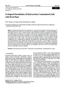
thermocouples and rhizons were inserted into the soil. Figure 1 presents a diagram of the
17
electrokinetic remediation plant (part a) and the instrumentation of the plant (part b) with
18
the notations that will be used in the discussion of the results.
19 20
Experimental setup
- + Anolyte reservoir
Level controller
V
I
Power supply
LIC
Electrovalve
Leak point Catholyte reservoir
Peristaltic pump
Cathodic wells
Anodic wells
Electrokinetic reactor
a)
1
P1, P2 y and P3 Cathodic wells P4, P5 y P6 Anodic wells TT1-TT5 Thermocouples T1-T6 Tensiometers R1-R9 Rhizons
● Leak point
External zone
Electrochemical zone
Electrokinetic zone
Electrochemical zone
External zone
b)
2 3
Figure 1. a) Diagram of the electrokinetic remediation plant; and b) Diagram of the
4
instrumentation used in the electrokinetic remediation plant
5 6
2.4.
Experimental procedure
7 8
Once the plant was completely instrumented, the experimental procedure began by
9
polluting the soil (simulating accidental spill). Thus, in the central point of the
1
electrokinetic reactor, an accidental leak of 6.250 dm-3 of an aqueous solution of 500 mg
2
2,4-D dm-3 (leak rate of 0.085 dm3 h-1) was simulated. Then, the electrolyte wells (water,
3
pH 7.64 and 0.391 mS cm-1 of conductivity) were filled. The level of the electrolyte wells
4
was controlled by a level control system connected to the feed tank, which adjusted the
5
volume of water added to the soil. The test began when the power source, a 400 SM-8-
6
AR ELEKTRONIKA DELTA BV, turned on and applied a constant voltage gradient of
7
1 VDC cm-1.
8 9
During the experiments, the pH, conductivity, and 2,4-D concentration of the hydraulic
10
fluids were monitored. Hence, the anolyte sampling was conducted manually while the
11
catholyte sampling was conducted by pumping the water accumulated in the cathodic
12
containers. The gravity fluid was sampled daily (5 cm3) and drained at the end of the
13
process through an outlet situated at the bottom of the reactor. The electrical current,
14
temperature, pH, moisture and 2,4-D concentration in the electrolyte wells were
15
monitored daily, and at the end of the experiments, an in-depth sectioned analysis of the
16
complete soil section was performed.
17 18
2.5.
19
To quantify the amount of 2,4-D in the soil, an L-S extraction process is used. This
20
process is performed in Eppendorf tubes (15 ml) using water as a solvent (ratio polluted
21
soil/solvent = 0.2 w/w). Both phases were vigorously stirred in a VV3 VWR multi-tube,
22
and the subsequent phase separation was accelerated using a centrifuge rotor angular
23
CENCOM II P-elite. The 2,4-D concentration in the aqueous phase was determined using
24
UV–visible spectrometry (Shimadzu UV–1603) at a wavelength of 283 nm.
25
Analyses
1
3.
RESULTS AND DISCUSSION
3.1.
Dispersion of 2,4-D in the natural soil
2 3 4 5
To determine the dispersion of 2,4-D in a natural clay soil, an accidental leak of this
6
herbicide was simulated. Thus, 6.215 dm-3 of an aqueous solution of 500 mg 2,4-D dm-3
7
was spilled over 6 days with a leak rate of 0.000945 dm3 h-1 (to avoid the formation of
8
puddle in the soil surface). It was fixed based on the percolation rate and the structural
9
properties of the natural soil used. The concentration of 2,4-D in the soil after the pollution
10
process was 20.71 mg of 2,4-D kg-1 of soil. Then, to guarantee the natural dispersion of
11
the pollution, the soil was not handled until days 26 and 70, which is when soil samples
12
were obtained to determine the pH, conductivity, moisture and 2,4-D concentration
13
distribution in the soil matrix. Thus, the soil was divided in 16 superficial zones (4x4) and
14
3 different layers (surface, middle and bottom layers) of 1 cm thick each. Table 2 provides
15
the average values of the measured variables in the three soil layers, which divides the z-
16
axis.
17 18
Table 2. Characterization of the soil after 26 and 70 days of the spill stage 26 days
70 days
Top
Middle
Bottom
Top
Middle
Bottom
pH
8.67
8.67
8.68
8.42
8.40
8.39
(mS cm-1)
0.218
0.212
0.217
0.224
0.213
0.225
Moisture (%)
12.76
13.10
13.77
6.86
9.74
10.49
11.09
11.14
12.45
10.03
11.27
10.38
2,4-D (mg
gsoil-1)
19 20
As can be observed, the pH and conductivity are fairly uniform after 26 and 70 days of
21
natural dispersion. This uniformity suggests a rapid dissemination and standardization of
1
the contaminants after the leakage occurs. Likewise, as it was expected, the moisture
2
value increases from its initial value of 11% to an average value of approximately 13%
3
after 26 days and subsequently decreases to 9% after 70 days. The initial increase is
4
clearly attributable to the discharge of the 2,4-D aqueous solution (which would cause the
5
moisture to potentially reach 21% if there were no other phenomenon, such as
6
evaporation). The further decrease that occurs between 26 days and 70 days can be
7
explained in terms of the evaporation of water and the lack of water supply during this
8
period. Furthermore, it also explains that the surface layer has a lower moisture compared
9
to that of the other layers of soil (12.76 vs. 13.77% at 26 days and 6.86 vs. 10.49 % at 70
10
days). For the 2,4-D solution, it was observed that it was rapidly dispersed through the
11
matrix soil, even though its distribution was not completely homogeneous; its
12
concentration was lower in the upper region (10.03 mg 2,4-D kg-1 of soil after 70 days)
13
compared to that in the middle and bottom regions (11.27 and 10.38 mg 2,4-D kg-1 of soil
14
after 70 days, respectively). Moreover, the total amount of 2,4-D in the soil, which is
15
calculated by a mass balance at 70 days, is 1,427.6 mg instead of the expected 3,107.5
16
mg added initially during the leakage period. This result indicates that 2,4-D is being
17
transferred to the gaseous phase.
18 19
To clarify these points, the transfer rates of the water and 2,4-D from the liquid to the
20
gaseous phase were estimated at two temperatures within the operating range (22.6 and
21
28.2 ºC). Thus, 0.5 dm3 of a high concentration aqueous solution of 2,4-D (500 mg dm-3)
22
was dumped in a methacrylate opened to the atmosphere reservoir with 3x15 cm2 of
23
surface area, and both the volume of water and the concentration of 2,4-D of the liquid
24
solution were monitored over time. Figure 2 depicts the fluxes of the water and 2,4-D
25
estimated after 200 h of testing.
1
2 3
Figure 2. Water () and 2,4-D (□) fluxes at 22.6ºC and 28.2ºC. Initial 2,4-
4
concentration: 500 mg dm-3, pH: 3.6.
5 6
As expected, both the evaporation of water and the transport of 2,4-D to the gaseous phase
7
occur, and they depend on the temperature, even in the close range of temperatures
8
evaluated (22.6 and 28.2 ºC). Based on the obtained water fluxes (0.0066 cm3 cm-2 h-1 and
9
0.0136 cm3 cm-2 h-1 at 22.6ºC and 28.2ºC, respectively), the expected maximum
10
evaporation rate in the electrokinetic reactor is 0.51 dm3 d-1 (assuming 48 x 68 cm2 of
11
surface area of the electrokinetic reactor and the rate of evaporation from a solution in
12
direct contact with the atmosphere). This value is significantly higher compared to that
13
obtained in the dissemination example (0.13 dm3 d-1), and this difference can be related
14
to the capillary barrier located at the top of the soil. From the average 2,4-D flux (0.0017
15
mg cm-2 h-1), it can be estimated that the amount of 2,4-D lost in the electrokinetic reactor
16
(with 48 x 68 cm2 of surface area) during the simulated leakage period is 799 mg
17
(approximately 50 % of the total amount lost during the dissemination test). This indicates
18
that the amount of pesticide dispersed to the atmosphere during an accidental leak of 2,4-
1
D solutions is extremely high, and it needs to be considered in this study. However, this
2
value is significantly lower than the amount of 2,4-D lost during the dissemination
3
example (1,679.89 mg of 2,4-D), which indicates that the capillary barrier located on the
4
top of the soil does not appear to have a major influence on the transport of this
5
contaminant.
6 7
3.2.
Dynamic study of the flushing-process of a natural soil polluted with 2,4-D
8 9 10 11
Figure 3 presents the time-lapse of the electric current applied between the rows of electrodes when the soil undergoes a constant voltage gradient of 1.0 VDC cm-1 (row of three anodic wells and row of three cathodic wells, according to Figure 1).
12 13
14 15 16
Figure 3. Time-lapse of the electric current applied between the rows of electrodes during the electroremediation of a natural soil polluted with 2,4-D; Operating conditions: Ez = 1 VDC/cm, and initial pollution: 20 mg 2,4-D kg-1 of soil
17 18 19 20
As can be observed, the electric current increases to a value of approximately 0.6 A after 200 hours of test (82 hours of operation). Then, the current begins to descend until it stabilizes at a value near 0.3-0.4 A after 700-800 h of operation. In an electroremediation
1 2 3 4
process, the current value depends strongly on the resistance of the soil, which depends on moisture, ionic concentration, temperature, etc. Therefore, its changes are related to the processes occurring in the soil. The consistently low current values observed over several days correspond to eventual operating problems in the experimental set up.
5 6
Figure 4 presents the changes in the volume of the electrolyte in both the anodic and
7
cathodic wells. During operation, tap water was continuously added to maintain the
8
electrolyte level in the anodic wells. Initially, the unsaturated soil indicated a tendency to
9
retain water; in this first stage, the soil moisture increased, and water did not accumulate
10
in the drain tanks placed next to the cathodic wells. After this initial period, water is
11
continuously accumulated in the drain tanks from where the catholyte is pumped and
12
analyzed. This fact is directly related to the electroosmotic flux (inset of part a), which
13
depicts an upward trend until it stabilizes at approximately 600 hours of testing. This
14
point matches with the stabilization of the electrical current mentioned above in Figure 3.
15 16
As it can be observed, the volumes added (anode wells) or accumulated (cathode wells)
17
depend on the particular well monitored. These variations may be related to the
18
heterogeneities and preferential pathways formed during the compaction stage. Another
19
important observation is that the volume accumulated in the cathodic wells differs from
20
the volume added in the anodic wells, and this difference can be related to the relevance
21
of the hydraulic fluxes (gravity and evaporation fluxes). In fact, at the end of the flushing-
22
process, a total volume of 5.13 dm3 of water was drained through an outlet situated at the
23
bottom of the reactor (gravity flux). Moreover, as stated previously, evaporation of water
24
during the EKSF process can occur.
1 2
Figure 4. Changes in the volume of electrolyte in both the cathodic (a) and anodic (b)
3
wells; Part a: ○ P1, □ P2, ∆ P3, total accumulated volume in cathodic wells; Part b: ○
4
P4, □ P5, ∆ P6, total added volume in anodic wells; and Inset of part a: electroosmotic
5
flux: ○ P1, □ P2, ∆ P3, accumulated flux
6 7 8 9 10 11
During the test, the observed trend was similar to that expected according to previous studies [32, 33]; the electrolyte well’s pH abruptly changed from its initial value (neutral pH) to a pH of 2 and a pH of 12 in the anodic and cathodic wells, respectively. These pH changes are related to the electrolysis of water, which leads to the production of protons inside the anodic wells and hydroxyl anions in the cathodic wells.
1 2 3 4 5 6 7 8 9 10 11 12 13 14 15 16
The applied electric field favors the movement of these ions through the soil, leading to primarily acidic and basic pH levels. Thus, changes in the pH of the soil are also expected, and they play an important role in the development of the precipitation and/or complexation processes of salts or metals in the soil. To verify this point, the pH of the aqueous samples obtained by the rhizons sited in the experimental set up (according to Figure 1b) was monitored during the electroremediation process. Figure 5 depicts the pH profiles of the aqueous samples extracted by the rhizons located in the electrochemical zone (R3 and R8), electrokinetic zone (R4, R5, R6 and R7) and external zone (R1, R2 and R9). As it can be observed in part a of the figure, the pH of the rhizons located near the electrolyte wells follow the expected trend: the pH values tend to become basic in the case of sampling points located near the cathodic well (R8) and acidic in the case of sampling points located near the anodic well (R3). In the rest of sampled sites in both the electrokinetic and external zones, the profile of the pH is a plateau, and the values monitored are close to neutral; furthermore, only the pH of the R9 rhizon sited in the external zone close to the cathodic well P2 appears to become basic.
1 2
Figure 5. Changes in the pH of the aqueous samples (sampled with rhizons sited in the
3
experimental set up); Electrochemical zone: R3, ■R8; electrokinetic zone: R4,
4
■R5,▲R6, ● R7; and external zone: R1, ■R2,▲R9
5
1
Figure 6 depicts the amount of 2,4-D accumulated in the electrolytic wells during the
2
flushing electroremediation process. As can be observed, the 2,4-D is rapidly transported
3
to the anodic wells, and although the profiles of the 2,4-D in the three anodic wells
4
initially overlapped, the amount of 2,4-D that is transported to the P4 wells is markedly
5
higher. This result confirms the existence of heterogeneities and preferential pathways in
6
the soil matrix which are a very important parameter and that even for setups with very-
7
well controlled operation parameters, such as the systems studied in this work, it is
8
difficult to obtain an accurate symmetry in performance. In addition to these transport
9
mechanisms, during the flushing process, the 2,4-D is also dragged due to the water flux
10
to the cathodic wells. The accumulation of the 2,4-D in both types of wells suggests that
11
it can be transported by electromigration to the anodic wells (because it has negatively
12
charged functional groups) and electroosmosis to the cathodic wells. The amount
13
recovered in both sites is similar (560.99 and 490.94 mg in the anodic and cathodic sites,
14
respectively); furthermore, the amount of 2,4-D present in the gravity flux drained
15
through an outlet situated at the bottom of the reactor (510.89 mg) is similar as well.
16
Considering the 2,4-D sampled in the rhizons during the process, the total amount of 2,4-
17
D recovered is 1586.62 mg (52.89 % of the 2,4-D added during the spill period).
18
However, the occurrence of 2,4-D in the gravity flux may involve a significant
19
contamination risk, and in case of full scale environmental events, such as those simulated
20
in this study, rapid action is recommended to remediate the site and prevent further spread
21
of pollution to groundwater once the soil pollution event has started.
22 23
1 2
Figure 6. Time-lapse of the amount of 2,4-D accumulated in the outflows during the
3
electroremediation of a natural soil polluted with 2,4-D; Operating condition: Ez = 1
4
VDC/cm, initial pollution: 20 mg of 2,4-D kg-1 of soil; a) Anodic wells: P4, P5,
5
P6 and b) Cathodic wells: P1, ■ P2,▲P3
6 7
3.3.
8
D
Steady state phase of the flushing-process of a natural soil polluted with 2,4-
9 10
After 1000 h of EKSF application, an in-depth sectioned analysis of the complete soil
11
section was performed to verify the amount of 2,4-D remaining in the soil as well as the
12
changes in the pH, moisture and conductive produced in the soil. Figure 7 presents the 3-
1
D maps of the moisture of the soil obtained post-analysis (2-D plots in three vertical
2
layers: surface, middle and bottom layers).
3 4
5 6
Figure 7. 3-D maps of the moisture in the soil after 1000 h of application of the EKSF;
7
Operating condition: Ez = 1 VDC/cm, initial pollution: 20.71 mg of 2,4-D kg-1 of soil; a)
8
surface layer; b) middle layer; and c) bottom layer
1 2
As can be observed, the moisture of the soil is generally quite homogeneous, except in
3
one corner of the electrokinetic reactor in which the moisture increases to values near 60
4
%. However, the average moisture values differ from the dispersion simulation study (see
5
Table 1), and in this case, the upper layer depicts a higher moisture (approximately 31 %)
6
compared to that of the intermediate and bottom layers (approximately 25 % in both
7
cases). This observation may be related to the location of the electrodes (water flows
8
primarily through the upper layers) and the effect of the capillary barrier. Thus,
9
considering the input of the water fluxes (in the anodic wells), output water fluxes (in the
10
cathodic wells and the gravity flux) and the initial water contained in the soil, it can be
11
estimated that the loss of water is approximately 31 dm3 (26.27% of the total added
12
water). This loss is within the range expected according to the previously mentioned
13
evaporation examples (21.5 dm3 and 43.4 dm3 at 22.6ºC and 28.2°C, respectively).
14
Therefore, it can be concluded that the 26.27% loss is due to evaporation, and the effect
15
of the capillary barrier is significantly lower than expected.
16 17
Figure 8 presents the 3-D maps of the pH of the soil after 1000 h of applying the EKSF
18
process. It should be noted that the pH in the electrokinetic zone tends to be neutral
19
whereas the pH in the cathodic zone (zone 1) tends to be basic; the highest pH value
20
occurs in the cathodic electrochemical area. However, in the anodic areas, the pH of the
21
water contained in the soil becomes more acidic, even though the profile observed in this
22
zone is less marked than that obtained in the cathodic zone.
1 2
Figure 8. 3-D maps of the pH of the soil after 1000 h of application of the EKSF;
3
Operating condition: Ez = 1 VDC/cm, initial pollution: 20.71 mg of 2,4-D kg-1 of soil; a)
4
surface layer; b) middle layer; and c) bottom layer
5 6 7
Figure 9 presents the 3-D maps of the 2,4-D (quantified as mg 2,4-D g-1 of dried soil)
8
remaining in the soil after 1000 h of applying the EKSF process. As it can be observed,
1
although there are zones in which the concentration of the 2,4-D is higher, the average
2
concentration of 2,4-D in the soil decreased from the initial 20 mg /kg to 4.84, 3.74 and
3
4.46 in the top, middle and bottom layers after the flushing process, respectively. It should
4
be noted that the remaining average amount of 2,4-D is similar in the three layers, which
5
indicates that the nearly homogeneous distribution of the herbicide should be achieved
6
before starting the flushing process (shortly after simulating the accidental spillage).
7
Likewise, the areas with fewer 2,4-D concentrations were the electrokinetic zone and
8
those near the anodic zone (zone 4). However, the cathodic area (zone 1) is the most
9
polluted zone of the treated soil.
10
1 2
Figure 9. 3-D maps of the concentration of 2,4-D (mg 2,4-D g-1 of dried soil) remaining
3
in the soil after 1000 h of applying the EKSF process; Operating conditions: Ez = 1.0
4
VDC/cm, initial pollution: 20.71 mg of 2,4-D kg-1 of soil a) surface layer; b) middle
5
layer; and c) bottom layer
6 7
From this data, it was evaluated that the amount remaining in the soil is 715 mg. As it
8
was stated previously, the total amount of 2,4-D transported to the electrolyte wells
1
(1,075.73 mg) and recovered with the gravity flux (510.89 mg) during the flushing
2
process was 1,586.62 mg. Hence, the air transfer loss of the 2,4-D (calculated by mass
3
balance) is 700 mg (approximately 50% lower than that obtained during the lab-scale
4
dissemination example). These losses may be linked to the air transfer during the leakage
5
process, indicating that the humidification attained in the electrokinetic treatment
6
minimizes the amount that is transferred to the air, which would be an important aspect
7
of the treatment. All of these results indicate that the electromigration is an important
8
mechanism in the flushing electroremediation of a natural soil polluted with 2,4-D
9
because, due to its negative charge, it is attracted to the positively charged electrode
10
(anode). A non-uniformity in the amount collected in each well is indicative of the soil
11
heterogeneity and the significant influence of this heterogeneity on the results. The
12
amount of pollutants contained in the cathode wells is also important, indicating that ionic
13
pesticides can be dragged by electroosmotic flux. Loss infiltration of the 2,4-D is
14
important but less than 30%, which is due to the significant water gravity flow, even in
15
the low permeability soil used. This loss is a significant risk that should be assessed in
16
the event of an actual treatment site because it would risk the quality of the underground
17
water reservoirs. Thus, the rapid action to prevent the quick spread of the pollution to
18
groundwater is recommended. Likewise, the use of capillary barriers on the surface of the
19
soil and of gas-extraction system in electrolyte wells can help to minimize the losses of
20
2,4-D to atmosphere.
21 22 23
4. Conclusions
24 25
The following conclusions can be observed as a result of this study.
1
- The decontamination of soils by EKSF is a feasible process for the remediation of 2,4-
2
D polluted soils., in which both electrokinetic and hydraulic fluxes place an important
3
role.
4
- During an accidental spill of 2,4-D into a low permeability soil, the herbicide can be
5
dispersed into the atmosphere extremely rapidly, and a significant ratio of the 2,4-D does
6
not pollute the soil. The 2,4-D solution that reaches the soil is distributed quickly and
7
evenly throughout the low permeability soil.
8
- Placing a capillary barrier on the surface of the soil allows a slow transfer of water by
9
evaporation but it does not have a significant influence on the pollutant transport.
10
- In an electrokinetic remediation process, the anion 2,4-D is mobilized towards the anode
11
primarily by electromigration. Furthermore, the 2,4-D is mobilized to the cathode by
12
electroosmotic drag; however, a lower concentration is measured because of the
13
extremely large volume of water mobilized. A non-uniformity in the amount of solution
14
added or collected in each well is indicative of soil heterogeneity and the significant
15
influence of this heterogeneity on the results.
16
- The EKSF technology with parallel facing rows of electrodes can eliminate
17
approximately 52.89% of the pollution by electrokinetic and hydraulic fluxes over a 40-
18
day test. Furthermore, volatilization is an important mechanism; however it appears to be
19
associated with the transfer during the leakage process simulation.
20 21
Acknowledgements
22 23 24 25 26
The authors acknowledge funding support from the EU and Spanish Governments through the MINECO Project CTM2013-45612-R and INNOCAMPUS.
1 2 3 4 5 6 7 8 9 10 11 12 13 14 15 16 17 18 19 20 21 22 23 24 25 26 27 28 29 30 31 32 33 34 35 36 37 38 39 40 41 42 43 44 45 46 47 48 49 50
References [1] A. Abdessalem, M. Oturan, N. Oturan, N. Bellakhal, M. Dachraoui, Treatment of an aqueous pesticides mixture solution by direct and indirect electrochemical advanced oxidation processes, International Journal of Environmental Analytical Chemistry, 90 (2010) 468-477. [2] M. Oturan, J. Aaron, Advanced Oxidation Processes in Water/Wastewater Treatment: Principles and Applications. A Review, Critical Reviews in Environmental Science and Technology, 44 (2014) 2577-2641. [3] C. Kwan, W. Chu, A study of the reaction mechanisms of the degradation of 2,4dichlorophenoxyacetic acid by oxalate-mediated photooxidation, Water Research, 38 (2004) 4213-4221. [4] M. Rodrigo, N. Oturan, M. Oturan, Electrochemically Assisted Remediation of Pesticides in Soils and Water: A Review, Chemical Reviews, 114 (2014) 8720-8745. [5] S.H. Hamdan, G.F. Molelekwa, B. Van der Bruggen, Electrokinetic Remediation Technique: An Integrated Approach to Finding New Strategies for Restoration of Saline Soil and to Control Seawater Intrusion, Chemelectrochem, 1 (2014) 1104-1117. [6] A. Ribeiro, J. Rodriguez-Maroto, E. Mateus, H. Gomes, Removal of organic contaminants from soils by an electrokinetic process: the case of atrazine. Experimental and modeling, Chemosphere, 59 (2005) 1229-1239. [7] A. Ribeiro, E. Mateus, J. Rodriguez-Maroto, Removal of organic contaminants from soils by an electrokinetic process: The case of molinate and bentazone. Experimental and modeling, Separation and Purification Technology, 79 (2011) 193-203. [8] P. Guedes, E. Mateus, N. Couto, Y. Rodriguez, A. Ribeiro, Electrokinetic remediation of six emerging organic contaminants from soil, Chemosphere, 117 (2014) 124-131. [9] M. Alcantara, J. Gomez, M. Pazos, M. Sanroman, Electrokinetic remediation of lead and phenanthrene polluted soils, Geoderma, 173 (2012) 128-133. [10] E. Mendez, M. Perez, O. Romero, E. Beltran, S. Castro, J. Corona, A. Corona, M. Cuevas, E. Bustos, Effects of electrode material on the efficiency of hydrocarbon removal by an electrokinetic remediation process, Electrochimica Acta, 86 (2012) 148-156. [11] E. Bocos, C. Fernandez-Costas, M. Pazos, M. Sanroman, Removal of PAHs and pesticides from polluted soils by enhanced electrokinetic-Fenton treatment, Chemosphere, 125 (2015) 168-174. [12] M. Alcantara, J. Gomez, M. Pazos, M. Sanroman, Electrokinetic remediation of PAH mixtures from kaolin, Journal of Hazardous Materials, 179 (2010) 1156-1160. [13] K. Maturi, K. Reddy, Simultaneous removal of organic compounds and heavy metals from soils by electrokinetic remediation with a modified cyclodextrin, Chemosphere, 63 (2006) 10221031. [14] K. Maturi, K. Reddy, Cosolvent-enhanced desorption and transport of heavy metals and organic contaminants in soils during electrokinetic remediation, Water Air and Soil Pollution, 189 (2008) 199-211. [15] H.I. Gomes, C. Dias-Ferreira, A.B. Ribeiro, Electrokinetic remediation of organochlorines in soil: Enhancement techniques and integration with other remediation technologies, Chemosphere, 87 (2012) 1077-1090. [16] S.A. Jackman, G. Maini, A.K. Sharman, G. Sunderland, C.J. Knowles, Electrokinetic movement and biodegradation of 2,4-dichlorephenoxyacetic acid in silt soil, Biotechnology and Bioengineering, 74 (2001) 40-48. [17] M.J. Harbottle, G. Lear, G.C. Sills, I.P. Thompson, Enhanced biodegradation of pentachlorophenol in unsaturated soil using reversed field electrokinetics, Journal of Environmental Management, 90 (2009) 1893-1900. [18] C. Girardi, K.M. Nowak, O. Carranza-Diaz, B. Lewkow, A. Miltner, M. Gehre, A. Schaeffer, M. Kaestner, Microbial degradation of the pharmaceutical ibuprofen and the herbicide 2,4-D in
1 2 3 4 5 6 7 8 9 10 11 12 13 14 15 16 17 18 19 20 21 22 23 24 25 26 27 28 29 30 31 32 33 34 35 36 37 38 39 40 41 42 43 44 45 46 47 48 49 50
water and soil - Use and limits of data obtained from aqueous systems for predicting their fate in soil, Science of the Total Environment, 444 (2013) 32-42. [19] O. Garcia, E. Isarain-Chavez, S. Garcia-Segura, E. Brillas, J.M. Peralta-Hernandez, Degradation of 2,4-Dichlorophenoxyacetic Acid by Electro-oxidation and Electro-Fenton/BDD Processes Using a Pre-pilot Plant, Electrocatalysis, 4 (2013) 224-234. [20] O. Garcia, E. Isarain-Chavez, A. El-Ghenymy, E. Brillas, J.M. Peralta-Hernandez, Degradation of 2,4-D herbicide in a recirculation flow plant with a Pt/air-diffusion and a BDD/BDD cell by electrochemical oxidation and electro-Fenton process, Journal of Electroanalytical Chemistry, 728 (2014) 1-9. [21] F.L. Souza, C. Saez, M.R.V. Lanza, P. Canizares, M.A. Rodrigo, Removal of herbicide 2,4-D using conductive-diamond sono-electrochemical oxidation, Separation and Purification Technology, 149 (2015) 24-30. [22] A.V. Schenone, L.O. Conte, M.A. Botta, O.M. Alfano, Modeling and optimization of photoFenton degradation of 2,4-D using ferrioxalate complex and response surface methodology (RSM), Journal of Environmental Management, 155 (2015) 177-183. [23] J.-M. Fontmorin, F. Fourcade, F. Geneste, D. Floner, S. Huguet, A. Amrane, Combined process for 2,4-Dichlorophenoxyacetic acid treatment-Coupling of an electrochemical system with a biological treatment, Biochemical Engineering Journal, 70 (2013) 17-22. [24] J.-M. Fontmorin, F. Fourcade, F. Geneste, I. Soutrel, D. Floner, A. Amrane, Direct electrochemical oxidation of a pesticide, 2,4-dichlorophenoxyacetic acid, at the surface of a graphite felt electrode: Biodegradability improvement, Comptes Rendus Chimie, 18 (2015) 3238. [25] J.W. Ma, F.Y. Wang, Z.H. Huang, H. Wang, Simultaneous removal of 2,4-dichlorophenol and Cd from soils by electrokinetic remediation combined with activated bamboo charcoal, Journal of Hazardous Materials, 176 (2010) 715-720. [26] Y. Acar, E. Ozsu, A. Alshawabkeh, M. Rabbi, R. Gale, Enhance soil bioremediation with electric fields, Chemtech, 26 (1996) 40-44. [27] D. Gent, R. Bricka, A. Alshawabkeh, S. Larson, G. Fabian, S. Granade, Bench- and field-scale evaluation of chromium and cadmium extraction by electrokinetics, Journal of Hazardous Materials, 110 (2004) 53-62. [28] Y. Lee, J. Choi, H. Lee, T. Ha, J. Bae, Pilot-scale study on in situ electrokinetic removal of nitrate from greenhouse soil, Separation and Purification Technology, 79 (2011) 254-263. [29] W. Kim, G. Park, D. Kim, H. Jung, S. Ko, K. Baek, In situ field scale electrokinetic remediation of multi-metals contaminated paddy soil: Influence of electrode configuration, Electrochimica Acta, 86 (2012) 89-95. [30] M. Villen-Guzman, J. Paz-Garcia, J. Rodriguez-Maroto, C. Gomez-Lahoz, F. Garcia-Herruzo, Acid Enhanced Electrokinetic Remediation of a Contaminated Soil using Constant Current Density: Strong vs. Weak Acid, Separation Science and Technology, 49 (2014) 1461-1468. [31] B. Kim, G. Park, E. Jeon, J. Jung, H. Jung, S. Ko, K. Baek, Field Application of In Situ Electrokinetic Remediation for As-, Cu-, and Pb-Contaminated Paddy Soil, Water Air and Soil Pollution, 224 (2013). [32] R. Lopez-Vizcaino, J. Alonso, P. Canizares, M. Leon, V. Navarro, M. Rodrigo, C. Saez, Electroremediation of a natural soil polluted with phenanthrene in a pilot plant, Journal of Hazardous Materials, 265 (2014) 142-150. [33] R. Lopez-Vizcaino, J. Alonso, P. Canizares, M. Leon, V. Navarro, M. Rodrigo, C. Saez, Removal of phenanthrene from synthetic kaolin soils by electrokinetic soil flushing, Separation and Purification Technology, 132 (2014) 33-40. [34] R. Lopez-Vizcaino, C. Saez, P. Canizares, V. Navarro, M. Rodrigo, Influence of the Type of Surfactant on the Mobility of Flushing Fluids for Electro-Remediation Processes, Separation Science and Technology, 46 (2011) 2148-2156.
1 2 3 4
[35] R. López-Vizcaíno, C. Sáez, E. Mena, J. Villaseñor, P. Cañizares, M.A. Rodrigo, Electro-osmotic fluxes in multi-well electro-remediation processes, Journal of Environmental Science and Health - Part A Toxic/Hazardous Substances and Environmental Engineering, 46 (2011) 1549-1557.