Remote Controlled Robot Arm Rko SafariE, Igor Hedrih, Rok KlobuEar
BoStjan sorgo
University of Maribor Faculty of Electrical Engineering and Computer Science Smetanova 17, SI-2000Maribor, Slovenia riko.safaric@uni-mbsi.
[email protected],
[email protected]
Po& Slovenije, d.o.0. SlomSkov trg 10,2500Maribor, Slovenia bOS~an.SOrgO@DOS~.Si
- The paper describes a method of education and training involving off-line usage of Virtual Environments (VE) for task planning. When programmed tasks of a robot a r m in the virtual world are developed to the satisfaction of the trainee, they are exported to a remote physical hardware, via the Internet, for the real world execution. The on-line feedback data from the robot a r m and live video picture are sent back to the remote client via Internet. Development of the Remote Laboratory @Lab) system connected with a remote controlled on-line video system and the training experiments are discussed, along with some of the issues raised for telerobotics.
bandwidth capacity, different methods of video transmission are used. Lately streaming video [6] applications such as Real Video, QuickTime Movie and Microsol? Media Player, are commonly used on the Internet.
Abstract
1 Introduction Training the students to work with expensive equipment, which is needed for canying out some practical educational work tasks has long proved problematical. In such a case of remote execution of educational laboratory exercises, the feedback of rich data from the physical hardware site to the operator site, via lnternet or Mobile Communications links, is bandwidth limited and contains uncertain delays. An approach that may bear much h i t is to use Virtual
Environments for achieving a simulated .“hands on” experience only connecting to physical hardware for short periods of time. In some cases difficulty may be experienced when trausfemng to full VE training. This situation may be ameliorated by migrating from simple control experiments for PID tuning [I]and an advanced control experiment supported by real-time video [2]. One of the first successful World Wide Web (WWW) based robotic projects was the Mercury project [3].This later evolved in the Telegarden project [4],which used a similar system of a SCARA manipulator to uncover objects buried within a defined workspace. Users were able to control the position of the robot arm and view the scene as a series of periodically updated static images. The university of Western Australia’s Telerohot experiment [SI provides Internet control of an industrial ASEA 1RB-6 robot arm through the WWW. Users are required to manipulate stack wooden blocks and, like the Mercury and Telegarden projects, the view of the work-cell is limited to a sequence of static images captured by cameras located around the workspace. Problems with the static picture can be avoided by using video technology. The transfer of video is currently the hardest task to be performed while transmitting data via the Internet. Because transfer of fluent video demands a high
0-7803-7852-0/03/$17.00 02003 IEEE
The previously mentioned projects [3], [4], [SI rely on cameras to locate and distribute system data and the current environment to the user via the WWW. It is clear that such an approach needs a high-speed network to achieve on-line control of the mobile robot. Data transmission times across the WWW depend heavily on the transient loading of the network, making direct teleoperation (e.g. the use of cameras to obtain a mobile robot position feedback) unsuitable for time critical and dangerous (e.g. collision between the robot arm and the environment) interactions. Rather than alIowing the nsers to interact with the physical resources directly, as in many of the previous examples, the reported approach, like [7] and [SI, requires users to configure the experiments using a simulated representation (e.g. a virtual robot arm and its environment) of the realworld apparatus. This configuration data is then downloaded to the real work-cell, for verification and execution on the real device, before returning the results to the user once the experiment is complete. This was done due to an unpredictable speed of communication via the Internet. For example: if a user made a mistake during offline programming, the real world robot arm movement could collide with an obstacle in the real world before the user could react and stop the process in the real world on the other side of the Internet connection. To prevent such a situation it was necessruy to incorporate collision detection software between a virtual robot am^ and a virtual environment in the virtual model. The virtual mobile robot and environment model is used, instead of cameras, to minimise the data transmission time through the network, so network speed is no longer a critical issue and solves the problem of mobile robot collision in the real world with a predictable environment. The presented approach uses socalled “platform independent” strategy which was not used in [7]and [SI.Authors in [7]and [8]used fast C-based collision detection and teach-pendant software, which has to run on special user hardware (personal computer) and software operating systems (Windows 95). Teach pendant software which enables users to run internet based telerobotics applications from any known hardware, operating system and browser platform, connected to the internet, is presented in the paper. For this purpose, a completely new type of remote lab server, called RLab, has been developed.
1202
IClT 2003 - Maribor. Slovenia
~
2 Remote robotics lab equipment The remote laboratory approach is based on the concept that it provides a working facility for off-line programming of actual working robot in a remote environment and hands-on training. It is desirable that the robot simulation should be capable of being executed through any standard WWW browser application, e.g. Netscape Navigator, Microsoft’s Internet Explorer etc [6] and VRML browser, e.g. Cortona or Cosmo Player etc. Standard browsers for the VRML 97 language don’t incorporate collision detection between shapes in the virtual world [7]. Because the adopted control strategy does not provide the remote user with immediate feedback from the actual work-cell, it is desirable that some kind of collision detection between the virtual robot and the virtual environment is created to prevent, or to predict, robot collisions in the real world.
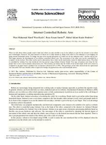
Fig. 1: A robot workcell with a m o t e contmlled vidco system
This problem has been solved by building JAVA oriented collision detection software [8] to assure platform independent approach. It may be solved with use of the complete browser [6] and collision detection software [ 5 ] in the CCe language which has capability to decrease the execution time of the complete software so as to increase animation speed as was done in [4] and [5] but it loses the platform independence.
the remote contiolled video system. The robot data and environment are constant and are set in the VR solbare. The remote motion data for the robot arm the camera mechanism are programmed and controlled, respectively, by the user. The work-cell includes the 5 axis educational robotic arm and 2 axis camera mechanism, manufactured in our laboratory which have P-position written by Mathworks’ MATLAB (ver.6.1) / Simulink / Real Time Workshop I xPC Target fast prototyping software.
The user must fust just connect his computer, via the internet, to the WEB page of the RLab server. Communication between the virtual robot model of the robotic manipulator, which is viewed by the remote user, and the control system which positions the joints of the actual manipulator is achieved as follows: authentication, error checking and user mntime scheduling on the RLab server, the user develops a robot task within the virtual environment on the WEB page of the RLab server, the collision detection routine on users side is performed and if no collision occurs in virtual world, the completed robot task file from the remote user, via the RLab server, is sent to a laboratory execution computer (a robot workcell), execution of the requested task within laboratory workcell, and finally collation and return the results via RLab back to the remote user (actual position of robot axes and on-line live video picture). The physical test equipment includes: a WWW network server, a network layer, a robot workcell, and remote user computers. The WWW network server is responsible for processing the requests for information by an external WWW browser, installed on the user’s remote personal computer, delivering on-line documents and providing access to the robotic and control hardware. The robot work-cell and remote controlled video system, shown in Fig. 1, allows Point to Point (PTP) motion of the robot and also observing the robot workcell on-line via
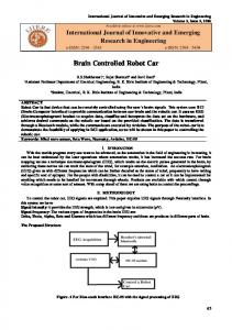
The program is executed by xPC operating software on the personal computer (PC), which has all the necessary software drivers written for power electronic and incremental encoder hardware. The robot arm and camera mechanism controllers achieve a constant sampling time for the position control loops, leaving the WWW server free to concentrate on the network interface and services user browser requests, thus overcoming the aperiodic sampling problems. 2.1 Software organisation Following the success of the earlier experiments [SI and [6], the development of an improved human computer interface, integrating the Java language and VRML language within a non-immersive desktop virtual reality environment, was undertaken in order to help improve the realism and sense of presence the user feels when programming the robot. This simulation tool allows the kinematics behaviour of the system to be studied, and permits research into task planning, process synchronisation and the communication issues involved with the control of robotic manipulators. The additional processes which are executed by the RLab and both executive servers for robot arm and camera server are shown in Fig. 2. Fig. 3 illustrates the users view of two robot arm models and its associated ‘virtual’teach pendant. The left robot arm model is a presentation of the “virmal robot arm”which is used for the programming of the robot arm movements. The right robot arm model shows the actual position of the real robot arm in the
1203
Client’s computer VRML browser camera controls
robot controls
2.2 Interface to the server The remote user is connected to RLab’s WWW site to register the job using an on-line form. The user details are processed by a CGI program running on the server, to determine user authentication, access control and job queue status. If the work-cell is available for use then the task is sent to the robot controller, thus allowing the user to view the experiment via an online camera immediately. If the workcell is currently in use then the users may decide to cancel their job and try again later, otherwise the file is placed in a queue for execution at a later date. In this case an acknowledgement will be returned to the user and the results stored in an on-line archive for retrieval at a later date. The acquisition of data from within the work-cell takes the form of on-line video footage (at 3-4 h n e s per second using internet videoconferencing) captured by a digital camera located in nearby the work-cell and numerical data (e.g. positional errors and timing information). Numerical data is collected via a data-logger and is returned at the end of the experiment, which allows the various joint trajectories to be studied graphically off-line.
Robot workcell
robot mechanism
control kernel
lI[&?k electronics, senson 1
Camera workcell camera mechanism
electronics. senson Fig. 2: The robot interface between servers and a client
virtual world as a result of feedback information from robot arm executive server.
Real time manipulator control is achieved using a separate computer (PC) control system. However, the existing controller requires that set points for limb movement, motor drive characteristics, process status, etc. are provided as a stream of parameters from a host computer, in this case the server, to the robot’s own control system, thus necessitating the development of a replacement command scheduling program written by Mathworks’ MATLAB (ver.6.1) I Simulink I Real Time Workshop / xPC Target fast prototyping s o h a r e . 2.3 Project results
The user invokes the experiment with simple start in the browser with RLab WEB address which run on the user side (see Fig. 2). The user has to connect the client browser to the RLab via internet, types the password, choose the right application (there is several other applications: LEG0 caterpillar mobile robot, robot arm MA 2000, mobile robot Nomad XR 4000 and our application called School Robot), first. The next step is initialisation which lasts between five and ten seconds. Here, the Java collision detection code and VRML code for the particular application are downloaded to the user computer. After this step, the user sees the teach pendant in his VRML browser and is able to communicate with an “on-line execution part” of the RLab server. A job scheduling and a data acquisition block of the on-line execution part of the RLab server, or simply xPC proxy, communicate with the executive PC server, which runs the robot workcell and camera workcell, via internet. The user is able to run the real robot and the camera mechanism with simple point-to-point (PTP) movement commands and receive the actual position values of the real robot arm.
1204
Fig. 3: Vimal teach pendant and robot model
The robot arm teach pendant’s collision detection library and its interface to the VRML robot model and communication with a browser has been described in [9].
respectively. The resulting values are the average values (22 measurements, half of them in the rush hours and half of them when internet lines were not busy).
The time spent for the execution of collision detection routine was less than 15 ms. The personal computer (Pentium I11 - 600 MHz, 256 Mbyte RAM, 3D accelerator, Windows 2000) was used as the user computer to perform the experiment. The time needed for VRML model execution was so small that it was neglected in the experiment.
So, the average overall tihe for the execution of VRML model visualisation, collision detection, communication between client, RLab server and xPC executive server is 702 ms for the fnst test and 1009 ms for the second test.
2.4 Two D.O.F. mechanism of the camera platform
The RLab server was the personal computer (Pentium I11 1 GHz, 256 Mbyte, Windows 2000) and the executive PCserver was an old fashioned 486 series personal computer.
The camera mechanism is capable to rotate the camera in two degree of freedoms. The next characteristics of the construction were concerned in the process of construction:
The maximum speed of the Ethernet communication link between both servers was 100 Mbps and also 100 Mbps in the fust test (University campus link) and 56 Kbps in the second test (analog modem via public telephone system) between the user’s personal computer and the RLah server.
mass of construction (use of light materials), simplicity and selection of available elements.
The time spent to send six desired values from client’s computer to the RLab server’s xPC proxy and six actual values vice versa was 207 ms for the fust test and 514 m for the second test. Sending six desired values from xPC proxy to xPC control kernel (robot workcell) and receiving six actual values vice versa lasts 317 ms and 163 ms,
Light materials such as galvanized thin plate, aluminium and plastics are used to achieve simple light weight mechanism. In static sense we do not deal with a huge load of the system.
1205
In this case one host and a target computer have been used. Matlab 6.1 with supplement xPC (required for ow
The ESCAP 28D11 servomotors for the axis' drives were used. As a matter of a fact, the servomotors are to powerful for our application. The drive is derived from a couple of cylindrical cogwheels with straight cylindrical cogs. Gear ratio between the cogwheels is i=9,1. An accord between the cogwheels is satisfactory, therefore, no setting up is required.
application) has been installed on the host computer. AD, D/A and incremental encoder cards are inserted in the server computer. The server's application task is position control of servo drives. Pulses, read with incremental encoder, are transmitted to the corresponding card. There are two 24 bit counters for counting pulses of incremental encoder and sending the position to the processor card.
The mechanism itself is made out of the bottom to which the lower supporting plate is attached. It serves for setting up the servomotor 1, and for formation of the lower cogwheels that rotate the camera horizontally. The upper supporting plate is screwed on the lower and serves to the same purpose as the lower one. The servomotor 2 is attached to the upper plate, so the second pair of cogwheels rotates the camera vertically. The camera is attached to the upper supporting plate with the particular holder which is in the same time the attachment for electronic link of the camera (see Fig. 1).
Two drivers are required for such an action. The first one is an algorithm with task of linking the incremental encoder and the server computer processor. It tuns with 2 ms sampling time. The second driver is organised as the fust one. Driver could be written as a C code programme or could be built with Sirnulink components. The Simulink components have been used in our approach due to the simplicity.
2.5 Control of camera mechanisms DC motors using xPC operational system
As was already mentioned motors are linked by xPC Target operational system that is a toolbox of MATLAEVSimdink 6.1 programme package. xPC target system enables an execution of the application in an external mode. An application can run on several host computers and one target computer to which controlled system is attached
The model built with Sirnulink blocks (Fig. 4) represents position control of the first servodrive with teleoperating in xPC target system. Desired value at the input of the model is presented in radians. The system could be controlled manually or automatically. Analog output of the DIA converter serves to provide referenced voltage to its output. Functional section (component) reads pulses kom the incremental encoder placed on the motors. The counters could be reset by Enabled Subsystem component counter. The system responses can be represent graphically or numerically. The position controllers for both axis of the DC servodrives are equal to the system shown in Fig. 4.
Dol. GENERATE lWUECiORY4
Fig. 4: Model ofposition caohol for teleoperating with xPC far first snvadrive
1206
[3] K. Goldberg; M. Maschna, Gentner S., et al., “Desktop Teleoperation Via The WWW,” Proc. of the IEEE International ConJ on Robotics and Automation, 1995, pp. 654-659.
3 Conclusion This paper introduces a new platform independent WWW based remute laboratory for robotics engineering students, which provides users with on-line access to the real-world hardware for remote experimentation. The approach requires the user to develop tasks off-line, using their remote computing resources, before submitting the experiment to the remote laboratoly server for execution on the actual device. The approach of using a non-immersive VR environment, with teach pendants to develop and simulate robot activity, (coupled with effective collision detection) prior to delivering the resulting control ‘“package” to remote physical hardware has proved very effective. The use of a web-cam video r e m enriches the exnerience. but it no longer needs to be a real-time flow. The reported approach offers significant education experiences whilst minimising the use of expensive or time constrained physical resources. The main goal - the development of a framework for teleoperating of mechatronics systems via internet has been achieved with the robot arm-application. However, the development of the Rlab system has not been finished, yet. The advantageous of the Rlab system are mainly the system administration, kom the system independent client application and modular architecture of the Rlab system which allows relative simple and inexpensive extension of the system with new mechatronics applications. The disadvantageous of presented system concept are communication delays and the execution time of some processes, so the Rlab system is not able to deal with the completely real-time teleoperating applications in a case of public internet use and poor communication connection (slow modems and ADSL ...) to the internet, The communication delays should be decreased with the use of simpler text transfer protocol instead of WEB service communication technology. It would certainty increase the communication speed, but on the other side, we would loose the ability of interconnection between different software and hardware computer platforms what is one of the most important goals of an good educational tool.
[4] httD://teleaarden.aec.at [5] httD://telerobot.mech.uwa.edu.au [6] A. Ioannides and C. Stemple, “The virtual art gallery/streaming video on the Web,” Proc. of the con$ on SIGGRAPH 98: conference abstracts and applications, 1998, pp. 154-159. [7] R. SafariE, M. Debevc, R. M. Parkin and S. Uran, “Telerobotics experiments via Internet,” IEEE transactions on industrial electronics, 2001, vol. 48, no. 2, pp. 424-43 1 . [SI R. SafariE, D. W. Calkin, R. M. Parkin and C. A. Czamecki, “Virtual environment for telerobotics,” Integrated. computer.-aided engineering, 2001, vol. 8, no. 2, pp. 95-104. [9] R. Safari& S. sinjur, B. Aalik and R. M. Parkin, “Control of Robot Arm with Virtual Environment via Internet,” Proc. I.E.E.E., 2003, vol. 91, issue 3, pp.
.^_
4LL-4LY.
[IO] httD://www.mathworks.co~uroducts/xuc~~e~
References D. W. Calkin, R. M. Parkin and C. A. Czamecki, “A PID Servo Control System Conducted Remotely Via Internet,” Mechatronics, 2002, Vol. 12, pp. 833-843. J.S. Hunter and J.C. Hung, ”Development of low-cost Multifunction sensors for lightweight fire and forget antitank weapon system,” IEEE Trans. Industrial Electronics, vol. 30, Feb. 1983, pp. 7-10. M. Golob, “Decomposition of a Fuzzy Controller Based on the Inference Break-up Method,” WSC3 The 3rd On-line World ConJ on Soft Computing p S C 3 ) . On the Internet kom 21-30 June 1998: btto:ii~.au.feri.uni-mb.si/-marian/WSC3~C-
l0.hhn 1207