Remote real-time control working over a wireless network Petr SIMACEK, Vladimir LUCAN, Jari SEPPÄLÄ and Hannu KOIVISTO Tampere University of Technology, Automation and Control Institute P.O. Box 692, FIN-331 01 Tampere, FINLAND, Tel: (03) 365 2087*, Fax (03) 365 2340
[email protected],
[email protected],
[email protected] and
[email protected] ABSTRACT This article presents case study considering real-time remote control using wireless UDP/IP-based networks. The aim of this research is to develop real-time remote control system based on a simulation model, which can operate via general communication networks, embodying modern wireless technology. The first part of the article includes a brief study of wireless communication principles as well as a short description of the current system. The second part describes measurement of the system and furthermore analysis of the test results. The conclusions are made based on the measured data of the system. Also, the encountered problems during the test simulations are raised up. A simulated process model is used instead of a real one in order to get comparable results; however, it indicates a good research tool and basis for future work in the realtime remote control research. At the end, some future development schemes of the system are discussed as well. Keywords: UDP/IP, Wireless network, Wireless local area network, Remote real-time control
1. INTRODUCTION The emergence of Internet and IP networks has raised remote control under the growing research areas. The possibilities of IP based communication networks and the advanced properties of multimedia transport together with huge growth of Internet connections have resulted in various numbers of applications and services, which have been developed during the past few years. In the future, remote control systems will be based on different IP communication networks. The current wired technology brings up difficulties in certain industrial environments such as mobile and portable machines. This project investigates the possibilities of replacing the wired technology with wireless. There are many challenges to be faced including the design of wireless system and also in the development of control system, that is wirelessly connecting together sensors, actuators and computers.
The main interest of this paper is the performance of wireless choices and the emerging difficulties in utilising wireless technologies in industrial environment.
2. INTRODUCTION TO WIRELESS NETWORKING The type of wireless network, described in this article has had many various names in the past, including terms like packet radio networks or multihop radio networks. The current commonly used name for a network managed by an Access Point (AP) is infrastructure network. Wireless Local Area Network (WLAN) has its standard since 1997 when IEEE released the norm 802.11. The last evolution of this standard has notation 802.11b and provides full Ethernet-like data rate of 11 Mbps. The development of the current standard clearly shows a need for increasing the data rate. The IEEE has already issued a specification 802.11a for equipment operating at 5-GHz frequency that supports up to 54-Mbps data rate. Moreover, the 5.7 GHz band promises to allow for the next breakthrough data rate of 100 Mbps. The purpose of Wireless Networks is to provide all features and benefits of traditional LAN technologies such as Ethernet but wirelessly. WLAN works without limitations of cabling using either infrared light (IR) or radio frequencies (RF) as a medium. Since infrared light requires the line of visibility for communication, the RF network is far more popular for its long range, higher bandwidth and wider coverage. The current WLAN technology uses the 2.4 GHz frequency band, which is the only unlicensed band in most of countries. Transmissions over a wireless medium are based on a spread spectrum method, which has been known for more than 60 years. There are two modifications of this method, which are widely used in WLAN and which are standardized by 802.11b. The first method is Fast Frequency Hopping Spectrum (FFHS) supporting data rates up to 2 Mbps. This method is also being used by Bluetooth devices. The second method is Direct Sequence Spread Spectrum (DSSS) and it supports data rates up to 11 Mbps. There are certainly many advantages of replacing cables by a wireless medium. The most significant are mobility, flexibility, cost saving, installation in difficult-to-wire areas and reduction of installation time.
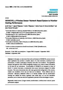
The main problem of wireless networks is the unreliability of the wireless medium, caused by a reflection, multipath effects and the crucial interference with other devices, which use the same frequency of 2.4 GHz [1,2]. Such as device could be for instance a microwave oven, an unshielded motor or other wireless appliance. 3. DESCRIPTION OF THE CONTROL SYSTEM Simulated models are used in order to represent a servomotor and a controller. Each of them is simulated in a separate industrial computer and connected via wireless network. The requirement of the project is to control position as well as rotation speed of the shaft. Therefore a multivariable control has to be used. The basic scheme of the control system is depicted in figure 2.
Controller
Speed Position
Process
Measurement
Figure 1: Control System description
Description of the system set-up This section tends to explain few terms of the current infrastructure system represented in figure 2.
Internet
Firewall
PC1
AP
PC2
Environment for development
Programmable logical controller (PLC) The programmable logical controller is a flexible industrial computer, intended for use in a wide range of industrial machines and applications of processes. PLC has typically modular construction and a wide scope of input/output modules. It consists of computer hardware, which is programmed to simulate the operation of individual logic and sequence elements. The PLC also supports programming of basic math functions that can be used for simulating controllers or other processes. Wireless Access Point (AP) Wireless access point performs functions similar to a hub in a cable network. Moreover it works as a filter for network traffic. It usually supports roaming which enables users equipped with wireless client adapters to freely move through a building. In addition to this, it also acts like an Ethernet bridge forwarding data from a wireless devices to a cabled devices and visa versa. Project required many parts of the IEEE specification, unavailable in most of commercial APs. These features include: support of multicasting traffic, since the PLC needs it for communication, 11 Mbps data rate, bridging, 40 and 128 bits encryption, and roaming Wireless Workgroup Bridge (WGB) It is a small, stand-alone unite, that provides wireless infrastructure connection for Ethernet-enabled devices. A device connected to a bridge communicates with a network infrastructure through a Wireless Access Point. The main idea of using Workgroup Bridge is to simulate WLAN-inPLC integrated unit. Special hardware requirements The first challenge was to find an Access Point that meets all requirement of the project; one of the crucial criterions was the support of multicast traffic, needed for downloading the initial PLC software from the server. After intensive testing of many Access Points, we can conclude that only Cisco Aironet 340 Series Access Point could fully satisfy all necessities. Another problem was caused by the bridging function. As can be seen from figure 2, system requires more than one Ethernet interface. Although two Access Points were implemented, the system could bridge the data only to one interface. As a result additional workgroup bridges had to be introduced to the system.
4. THE MEASUREMENT OF WIRELESS PERFORMANCE
Server
WGB1
WGB2
PLC1
PLC2
Figure 2: System description
There are many ways how to measure the performance of a wireless network. The two most important ones are throughput and delay. The throughput is a rate at which bits are transformed from a source to a final destination and it is measured in bits per second. The delay is defined as a time difference from the time when a bit enters the network at its source node to the time when it is correctly received at its destination node.
The principle is to measure the cycle delay caused by the network properties. Each packet transmitted from PLC1 to PLC2 goes from workgroup bridge 1, through access point, to workgroup bridge 2 and finally to PLC2. After reaching PLC2, the value is sent back to PLC1. This gives us sufficient opportunities to measure the time difference between the time of transmitting the packet, and the time when the same packet arrives to the PCR1 again. Additionally, the algorithm also calculates sent, lost and correctly delivered packets. Note, that the algorithm has an internal timer, which causes the program waiting for the delayed packet for a certain time. If the timer is exceeded a lost packet is indicated. The traffic was limited to specific clients using MAC address filtering, in order to enable more reliable reference measurement. Another issue was to rule out the wireless traffic used for normal office work at our institute. [1,2,5]
5. MEASUREMENT RESULTS
Figure 3: Flow chart of the measuring algorithm The delay measurement is critical especially for real-time applications such as real-time control or voice and video applications. However, real-time applications can afford to lose some packets. On the other hand, for a data transfer delay may not be so important, but accurate and complete reception is the crucial problem. The same problems of Quality of Service (QoS) known from TCP/IP networks also exist in wireless networks; furthermore, it means that the replacement of wired with wireless communication shall avoid changes in control design. There are some other measures such as the mean delay value or percentage of lost packets. One difficulty concerning the measurement is the analysing tool. Probably the only available tool currently on the market is AiroPeek, which is a comprehensive packet analyser for IEEE 802.11b wireless LANs, supporting all higher level network protocols such as TCP/IP, AppleTalk, NetBEUI and IPX. Regrettably the first version of AiroPeak was released very recently and therefore there was very little time for testing. Hence, regarding the purpose of this work to determine the network performance, an easy algorithm for measuring the delay effect was developed (figure 3).
Measurements were held under the following conditions: A – all devices were located inside one room on tract about 35 square meters; B – one of the workgroup bridges was placed behind 4 walls in an other room, distant about 40 meters. Although there were usual disturbances in the building, such as mobile phones, computers and other wireless access points, the influence to the measurements was very small. The testing showed, that the only device, which affected the wireless transmission was a microwave oven, which caused high lost of packets; however, this can be decreased by setting the device parameters such as robustness, RTS threshold etc. [6] Table 1 shows the main values of the measurement under condition A and B, and with certain type of encryption. It can be seen in figure 4 that the most of the values are between 16 and 18 ms, which is sufficient time for considered real-time model. On the other hand, it is clearly seen that the measured values dramatically vary, which leads to a problematic implementation of a real-time control algorithm, especially some advanced approaches concerning varying delays should be implemented. [4]
Encryption No 40-bits 128-bits
Con.
Mean
Min
Max
A
15.6
10
29
B
16.1
11
33
A
16.2
10
38
B
16.6
11
38
A
15.3
10
28
Tabl B 16.6 10 35 e 1. Measured out values (in milliseconds), timer = 100 ms
7. DISCUSSION There are many industrial environments, which can interfere with built wireless local area network, Those devices include unshielded engines, electric supplies and other devices that can evoke packet losses; therefore the area of the coverage network devices has to be properly explored, whether there is not source of disturbances. [4] Another challenge, which should be investigated, is the behaviour of the graph showing distribution of delays (figure 4). The most probable explanation seems that a task interval, defined in a PLC, can influence the measurement. This problem will be researched and analysed in the future. 8. CONCLUSIONS Figure 4. Example of delay distribution with and without implemented encryption (condition A)
6. ANALYSIS OF RESULTS The purpose of this work was to develop a test suite for wireless remote real-time control studies, to get reliable time delay values of an observed sample. According to measured results following perceptions can be discussed. Since the value of time delay fluctuates, as can be seen in figure 5, it can be declared that all results were reliable; there was no value over 38 milliseconds registered and all packets were delivered. On the other hand if there is a needed to control a device, which requires consistent regulation, difficulties can be met and this oscillation should be eliminated. This will be one of the future tasks for this project. In addition, measurement of lost packets was undertaken under different conditions; therefore we may conclude that only the poorly shielded microwave oven causes some interference with the built WLAN. The implemented prototype of a wireless remotecontrol environment is designed to be easily transported for on–site testing to an actual industrial site and therefore it is a good base for future work.
A wireless system was built, implementing Programmable logical controllers, Wireless Access points and Workgroup bridges. Several problems were overcome including difficult selection of an Access point, bridging and multicasting. A microwave oven was discovered as the biggest source of disturbance. Current testing brought a lot of new ideas for future development of the project such as implementing a real-time model of a process as well as a new control algorithm dealing with varying delay. Another issue is the on-side testing in a real industrial environment. This could help us to find new, yet unknown sources of disturbance.
9. REFERENCES: [1] Cisco, Overview –Wireless Local-Area Networking, (2001) [2] P.R. Kumar, New Technological Vistas for Systems and Control, IEEE Control Systems Magazine 2001 pp. 24 –37 [3] Mikell P. Groover, Automation, production systems and computer integrated manufacturing, ISBN: 0-13-088978-4, 2000 by Prentice Hall [4] Nicolas Andreff, Robustness of jitter in real-time systems, ISBN 0280-5316 (1994) [5] Wildpackets, Inc., Airopeak overview, (2001) [6] Cisco Systems, Cisco Aironet 340 Series – Installation guide
Figure 5. Example of measured sample