The sun position can enhance both the image alignment and color projection
phases. Moreover, the detection and removal of the shadows from the images ...
The 11th International Symposium on Virtual Reality, Archaeology and Cultural Heritage VAST (2010) A. Artusi, M. Joly-Parvex, G. Lucet, A. Ribes, and D. Pitzalis (Editors)
Removing shadows for color projection using sun position estimation M. Dellepiane, L. Benedetti, R. Scopigno Visual Computing Laboratory, ISTI-CNR, Italy
Abstract The result of an outdoors 3D scanning acquisition campaign is usually an accurate 3D model of the site, but in most of the cases the quality of the color acquired by the scanner is not satisfying. Alternative solutions, like the projection of a photographic dataset acquired in a different stage, are still dependent on the quality of the initial images. The short time for the acquisition campaigns and the weather conditions often force the shooting of images taken under a strong direct sun illumination. This generates colored models of poor quality. In this paper we present a method to estimate the sun position starting from a geo-referenced 3D model and a set of images. The sun position can enhance both the image alignment and color projection phases. Moreover, the detection and removal of the shadows from the images produces a better and more coherent color in the final 3D model. Using this kind of approach, outdoor sites can be acquired producing a high quality color information together with an accurate geometric measurement. Categories and Subject Descriptors (according to ACM CCS): I.3.7 [Computer Graphics]: Three-Dimensional Graphics and Realism —Color, shading, shadowing, and texture
1. Introduction The use of three-dimensional data in the context of Cultural Heritage is becoming more and more popular. While the cost of the acquisition hardware is still quite high, the commercial and freeware tools to process the acquisitions can provide ways to visualize and analyze complex data. Moreover, structure-from-motion techniques are becoming a low-cost alternative to generate 3D models starting from a group of images. An important type of data that should be added to the threedimensional models would be the surface appearance. Unfortunately, in this case the problem appears to be much more complex: especially for big artifacts, the setup for the acquisition of material properties is usually too complex for practical applications. The alternative approaches which extract the color information from groups of images are still heavily dependent on the quality of the starting dataset. Essentially, if the light position is unknown, the lighting artifacts are projected on the 3D model as if they were color information. Hence, the photographic campaign is performed c The Eurographics Association 2010.
under controlled lighting, in order to limit the presence of artifacts like shadows or highlights. When the object to be acquired is of big size and outdoor, there is usually no possible control on the lighting. A cloudy day usually provides an almost perfect (diffuse lighting, no shadows) environment, but usually the scanning campaign must be completed in a short time, and in some places of the earth (i.e. Africa, Asia, South America) cloudy days are quite rare. Hence, since the acquired images can present strong artifacts (hard shadows, highlights), it is necessary to detect and remove them. In this paper, we present an approach to improve the quality of color projection of images taken under direct sun illumination. The sun position at the moment of the photo shooting can be obtained if the three-dimensional data are geo-referenced, and the time and date of the photo is known. If the sun position is known, then:
• The image alignment process can be speeded up
Dellepiane et al / Removing shadows
• The shadows positions in the image can be automatically detected. Then, it is possible both to try to remove the shadows, and to ignore specific portions of the image during the projection phase. The final colored 3D model will present a more realistic appearance, and it could be possible to apply the present approach to a previously acquired dataset. 2. Related Work The work proposed in this paper is related to several topics in Computer Graphics and Computer Vision research: controlled light environments, light modeling, material properties acquisition, computational photography. We will focus on two of the most relevant subjects: color information acquisition and mapping, and illumination artifacts removal. References to other related research fields (i.e. material properties or illumination estimation) can be found in the context of the other sections of the paper. Mapping of color information on 3D models. Given the difficulty in acquiring the complex material properties of a real object, an alternative solution is to try to obtain the "unshaded" color from a set of images. The value is mapped on the digital object surface by registering those photos w.r.t. the 3D model (computing the camera parameters) and then by applying inverse projection, transferring the color from the images to the 3D surface. Despite the simple approach, there are numerous difficulties in selecting the correct color to be applied (when multiple candidates are present among different images). Essentially, it’s necessary to deal with the discontinuities caused by color differences between photos that cover overlapping areas and to reduce the illuminationrelated artifacts (shadows, highlights, peculiar BRDFs). A first method to decide which color has to be applied to a particular area of the model is to select, for each part of the surface, an image following a particular criterion that, in most of cases [CCS02, BAF04, LHS00], is the orthogonality between the surface and the view direction. In this way, only the "best” parts of the images are chosen and processed. Artifacts caused by the discordance between overlapping images are then visible on the border between surface areas that receive color from different images. Between those adjacent images there is a common, redundant zone: this border can be used to obtain an adequate corrections in order to prevent sharp discontinuities. This approach was followed by Callieri et al [CCS02], who propagates the correction on the texture space, and by Bannai et al [BAF04], who used the redundancy to perform a matrix-based color correction on the original image, and more recently by Gal et al [GWO∗ 10]. Other approaches, like the one proposed by Lensch et al. [LHS00] do not work only on the frontier area, but blend on the 3D surface using the entire shared content to smooth out the discontinuities.
Instead of cutting and pasting parts of the original images, as the previous approaches have done, it is possible to assign a weight to each input pixel (this value expresses the "quality" of its contribution), and to select the final color of the surface as the weighted mean of the input data, as in Pulli et al [PARD∗ 98]. The weight is usually a combination of various quality metrics. This weight-blend strategy has been introduced in various papers [BMR01, Bau02, RLE∗ 05], with many variants in terms of number and nature of assembled metrics. In particular, Callieri et al [CCCS08] presented a flexible weighting system, that could be extended in order to accommodate additional metrics. A more recent work [DCC∗ 10] uses flash light as a controlled light to enhance the color projection on 3D models. Most of the analyzed methodologies present a common operation: the possibility to discard parts of the input images or to selectively assign a weight to contributing pixels. These features can be extremely valuable once that, in the context of our method, the shadows have been detected: even if they are removed using image processing, the corrected portions can be assigned to a lower quality value in order to be used only if needed. Artifacts removal and Flash/No-Flash use in Digital Photography. The removal of artifacts from images is an operation which can be valuable for several fields of application, hence it has been widely studied. There are a number of artifacts removal techniques which have been proposed in the last few years. They can be roughly divided in two subgroups: the ones working on a single image [Wol89, TLQS03, OT06, SZSX08, FF06, FDL04], which are mainly based on the analysis of the colors of the image, and the ones using a set of images [SI93, LYK∗ 03], which take advantage of the redundancy of information between images. In general, these methods assume no prior information about the geometry of the scene. More recently, the use of flash/no-flash pairs to enhance the appearance of photographs has been proposed in several interesting papers. These works [HT03, ED04, PSA∗ 04] proposed techniques to enhance details and reduce noise in ambient images, but also propose simple ways to remove shadows and highlights. Results are very interesting, but the techniques can be applied only when the flash light is the dominant one in the scene. This prevents from their use in outdoor environments. Flash/no-flash pairs are used by [LDF06] to detect and remove ambient shadows. In the work by Dellepiane et al [DCC∗ 10] a framework for the detection and removal of lighting artifacts produced by flash light is presented.
3. Modeling the sun: light direction estimation The direct sunlight usually represents an issue for photographers, due to the strong lighting on exposed surfaces and the hard shadows produced. c The Eurographics Association 2010.
Dellepiane et al / Removing shadows
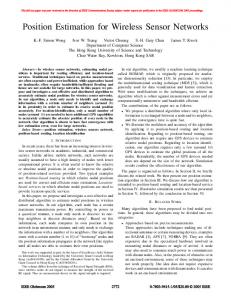
Figure 1: Left: an image with sun light illumination. Center: the rendering of the corresponding model using ambient occlusion and normal maps. Right: the rendering of the corresponding model with normal maps and shadows generated by the estimated sun light direction.
But at the same time, due to its distance with respect to the earth, the sun light source can be easily approximated as a directional one, where the light direction is the same throughout the scene. Hence, to model the sun light it is necessary only to know the angle between it and the surfaces. During the acquisition of the images, it is possible to acquire the sun position and other data by using ad-hoc devices [JTS∗ 04,CCC08]. Recently, other approaches try to estimate the sky environment directly from images [LEN09, LNE10]. If no acquisition device is available, and accuracy is needed, several simple online tools [Suna, Sunb, Sunc] can calculate the sun position, which is usually expressed with two angles, the azimuth (which is mostly defined as the angle along the horizon, with zero degrees corresponding to North, and increasing in a clockwise fashion) and the elevation (which is the angle up from the horizon). The input data needed for the calculation are data about the site location (e.g. latitude and longitude) and the date and time when the image was taken. The site position can be acquired by acquiring the GPS coordinates of some reference points: with at least three points, the corresponding 3D model can be geo-referenced so that its orientation is aligned to the north direction. The date and time can be easily retrieved from the EXIF metadata of the image: in this way, all the needed input to get the sun lighting direction is available. Alternatively, there is a manual procedure that can be used to estimate the sun light direction. The approach is similar to the one used in [DCC∗ 10] to estimate the flash light position: first, the user needs to align the image on the 3D model. Then, it’s necessary to indicate on the image a point on the 3D model (like a corner or a strong geometric feature) and its corresponding projected shadow on the 3D model. If the image is aligned to the model, this identifies two points in the space which should define the sun direction for that image. Indicating several couples of points and averaging the resulting direction could lead to an accurate enough estimation. Once that the sun direction is known, both the alignment and the projection phases can be enhanced in order to proc The Eurographics Association 2010.
duce better results: the next Section will show how this is implemented. 4. Shadows detection and removal The sun direction estimation transforms a generic color projection dataset in a dataset with a controlled light setup. This greatly enhances the possibilities in most of the steps of the color projection pipeline: image alignment, image correction and color projection. The next subsections will show how this can be easily exploited. 4.1. Image alignment using sun direction information When dealing with an un-calibrated set of images, the preliminary step of image alignment can be quite difficult and time consuming. While the semi-automatic solutions [FDG∗ 05] proved to be robust, but it is still time consuming if applied to a set of images. A more recent technique [CDPS09] uses mutual information to fit a illumination related rendering of the 3D model to the image. In the original idea, the most robust rendering was a combination of normal maps, related to directional illumination, and ambient occlusion, accounting for diffuse component. In our case, since the light direction is known, it’s possible to substitute the ambient occlusion with a shadow mapping on the 3D model. In this way, the shadows are in the same position as in the image, and the convergence of Mutual Information maximization is faster and more precise. Figure 1 shows an image and two renderings of the corresponding models using ambient occlusion and shadows generated with the estimated sun light direction. The second type of rendering is clearly much more correlated to the appearance of the real object, so that the image alignment process is much more fast and robust.
4.2. Shadow masks creation and image correction Once that the image alignment is complete, all the needed data for the color projection are available. But before the
Dellepiane et al / Removing shadows
final step, it is possible to further use the light direction information. First of all, in a similar fashion to the shadow detection feature of [DCC∗ 10], it is easy to create a shadow mask that indicates which portions of each image of the photographic dataset are in shadow. The comparison between a rendering from the image point of view and a rendering from the light direction shows that all the points which are visible from the camera location, but not visible from the light direction can be considered to be under shadow. Figure 2 shows an image and the corresponding shadow
with this method is the fact that we already have the shadow maps. The shadow removal procedure follows these steps: • Coarse shadow edges locations are identified. A portion of the image around each edge location is considered, since the quality of shadow maps is not always perfect (see later for a discussion on this drawback). • For every edge zone, the maximum intensity difference (offset) between the illuminated and the shadowed part is obtained. A lowpass filtered version of the images is used, in order to remove noise. Moreover, if the portions in shadow and in light of the zones are not uniform, the zone is not taken into account in order to prevent from inaccurate corrections. • The obtained offsets are interpolated with a pullpush algorithm [GGSC96] to obtain smooth non-constant values. These offsets are summed to the shadow region. • Finally, the shadow edges are deleted and recovered by pullpush interpolation, to ensure minimization of the errors. The algorithm is almost automatic except for a parameter, which defines the size of the edge zone where the shadow edges need to be found. This parameter is dependent from the quality of the shadow mask, and it can be changed in order to deal with difficult cases, where for example the threedimensional geometry is not accurate enough to obtain good shadow masks.
Figure 2: Left: an image with direct sun light illumination. Right: the shadow mask extracted after image alignment to the digital 3D model. mask: the silhouette of the main shadows is extracted in a very accurate way. The shadow masks can be used during the projection phase, in order to weight the contribution of the portions of the image to the final color, but they can be also valuable to try to pre-process the images. In the last years, several techniques to remove shadows from an image have been proposed [AHO07, SL08, MMI09, FDL09, FDL04, FF06], but the shadow detection is usually a semi-automatic process [SL08,MMI09], although some quite robust techniques have been proposed [FDL09, FDL04, FF06]. In our case, the possibility to calculate the shadow maps permits to skip the initial step, so that the image correction can be made in a completely automatic way. Our approach is inspired by [FF06]. The main difference
Figure 3 shows two examples of image processing: the first column shows the original images, the central column shows the shadow masks used for correction, the right column shows the results. As it can be noted, the original color of the object is reconstructed with sufficient accuracy, and also the detail of the surfaces is preserved. Some artifacts are present only on the border of the shadows. The third examples shows a more complex case, with different colors throughout the scene. The shadow removal obtains acceptable results. A portion of shadow was not removed because it was not detected, since it was generated by some structure (a wall portion) which was not part of the digital 3D model. These artifacts can be generated by the small errors of the shadow maps, which are sometimes generated by threedimensional models not accurate enough to reproduce the shadows in the images. The correction of these artifacts would require some intervention by the user, in order to correct the shadow maps or weight the shadow removal in a different way. In the context of the proposed system, it was decided to preserve the fully automatic approach, by taking into account that the portions of the images which contain artifacts can be known in advance: hence, using the quality weighting factor in the color projection phase (see next Section), it’s possible to assign a very low quality value to these zones, so that they are used only when no contribution comes from other images. c The Eurographics Association 2010.
Dellepiane et al / Removing shadows
Figure 3: Left column: an image with sun light illumination. Center column: the shadow mask used for image correction. Right column: the result of shadow removal.
4.3. Color projection The results obtained in the previous sections can be used in the final step of color projection. Hence, it’s possible to use the corrected images in order to obtain a more coherent colored model. For example, the previous processes can be easily implemented in the context of the framework proposed in [CCCS08]. Moreover, the shadow masks extracted in the previous section can be integrated in the weight masks feature of the projection system: for example, a lower weight can be assigned to the portions of the images which underwent the shadow removal, so that they could be used only when the contribution of other images is not good enough. The results of this projection phase are shown in the next Section. 5. Results The proposed approach was applied on a number of dataset, mainly coming from the African Heritage. Especially in these cases, the acquisition campaign are performed during the dry season, when the weather is usually very sunny. As c The Eurographics Association 2010.
a result, most of the photographic campaigns are performed under strong sun light, presenting hard shadows in almost all the images. Starting from set of multiple images, the results obtained with the classic projective approach were compared with the proposed technique. A first example is shown in Figure 4, where six images have been mapped in a portion of the ruins of a temple. Since all the photos were acquired in a short time, the position of the shadows did not change noticeably. While the rendering is obtained using a soft diffuse lighting, hard shadows independent from the light environment are noticeable on the scene. Even the blending approach of [CCCS08] is not able to mask them, because some portions of the surface are covered only by images in shadow. The resulting threedimensional model presents strong artifacts (Figure 4,top). An alternative solution could be to perform photographic campaigns in different times of the day, and then to mask the images by not projecting the parts in shadow: but this operation would be time consuming, and the coherency of the final color is not guaranteed. But if the images are processed using the proposed approach,
Dellepiane et al / Removing shadows
Figure 4: Top: a rendering of the 3D model without shadows removal. Bottom: a rendering of the 3D model with shadows removal.
the resulting model (Figure 4,bottom) shows a much more realistic color. Only a few artifacts are still remaining, but the model can be re-illuminated with a higher degree of realism. Figure 5 shows a second example, where the original shadows are smaller but still noticeable. Also in this case (four images projected on a portion of a temple), the shadows are removed from the final three-dimensional model, so that the appearance and the navigation result to be more realistic. The method was applied on several other test cases, resulting in evident improvements on the meshes. The main limitations of the approach are related to the accuracy of the initial dataset: if the 3D model is not accurate, the shadow masks could not be precise (also when the sun direction in appropriately estimated). Moreover, the accuracy of the geometry influences also the color projection phase. Moreover, if the shadows on an image were generated by external objects (people, parts of the site which haven’t been acquired) these artifacts cannot be corrected by our approach. In this case, the user shall intervene with semiautomatic image-based approaches. 6. Conclusions In this paper we presented a method to use the sun position to improve the color projection pipeline. If the sun position
Figure 5: Top: a rendering of the 3D model without shadows removal. Bottom: a rendering of the 3D model with shadows removal.
associated to an image can be recovered, all the steps of the pipeline (image alignment, image processing and color projection) can be made more robust and reliable. Moreover, the entire process can be implemented in a completely automatic way, and integrated in existing frameworks. We have several possible directions for future improvements: • Existing image-based techniques can be further integrated in order to improve the accuracy of the shadow maps, correcting errors due to the quality of the 3D model or the sun position estimation. • The shadow removal could be enhanced by taking into account the overlapping portions of all the images. • The images could be processed by modeling the sun light and correcting the effects of light also on exposed surface (like the saturated colors produced by strong sun light). In conclusion, the proposed approach can be easily applied in the field of Cultural Heritage, also because it does not add any additional effort during an acquisition campaign, where all the needed data (GPS coordinates, images) are already acquired as a routine. Hence, also databases of past acquisition can be used to improve the resulting 3D model. c The Eurographics Association 2010.
Dellepiane et al / Removing shadows
7. Acknowledgements The research leading to these results has received funding from the European Community’s Seventh Framework Programme (/FP7/2007-2013), through the 3D-COFORM project, under grant agreement nˇr 231809. We would like to thank also the Zamani Project team (http://www.zamani-project.org/) for providing us some of the datasets. References
[GGSC96] G ORTLER S. J., G RZESZCZUK R., S ZELISKI R., C O HEN M. F.: The lumigraph. In SIGGRAPH ’96: Proceedings of the 23rd annual conference on Computer graphics and interactive techniques (New York, NY, USA, 1996), ACM, pp. 43–54. [GWO∗ 10] G AL R., W EXLER Y., O FEK E., H OPPE H., C OHEN -O R D.: Seamless montage for texturing models. Computer Graphics Forum 29, 2 (2010), 479–486. [HT03] H OPPE H., T OYAMA K.: Continuous Flash. Tech. Rep. MSR-TR-2003-63, Microsoft Research, 2003. [JTS∗ 04] J ESSI C. T., T CHOU C., S TUMPFEL J., E INARSSON P., FAJARDO M., D EBEVEC P.: Unlighting the parthenon. In SIGGRAPH 2004 Sketch (2004), ACM Press.
[AHO07] A RBEL E., H EL -O R H.: Texture-preserving shadow removal in color images containing curved surfaces. In Conference on Computer Vision and Pattern Recognition (CVPR 2007) (June 2007), IEEE Computer Society.
[LDF06] L U C., D REW M. S., F INLAYSON G. D.: Shadow removal via flash/noflash illumination. Multimedia Signal Processing, 2006 IEEE 8th Workshop on (Oct. 2006), 198–201.
[BAF04] BANNAI N., AGATHOS A., F ISHER R.: Fusing multiple color images for texturing models. In 3DPVT04 (2004), pp. 558– 565.
[LEN09] L ALONDE J.-F., E FROS A. A., NARASIMHAN S. G.: Estimating natural illumination from a single outdoor image. In IEEE International Conference on Computer Vision (2009).
[Bau02] BAUMBERG A.: Blending images for texturing 3d models. In BMVC 2002 (2002), Canon Research Center Europe.
[LHS00] L ENSCH H., H EIDRICH W., S EIDEL H.: Automated texture registration and stitching for real world models. In Proc. 8th Pacific Graphics 2000 Conf. on Computer Graphics and Application (Los Alamitos, CA, 2000), IEEE, pp. 317–327.
[BMR01] B ERNARDINI F., M ARTIN I., RUSHMEIER H.: Highquality texture reconstruction from multiple scans. IEEE Trans. on Visualization and Computer Graphics 7, 4 (2001), 318–332. [CCC08] C ORSINI M., C ALLIERI M., C IGNONI P.: Stereo light probe. Computer Graphics Forum 27, 2 (2008), 291–300. [CCCS08] C ALLIERI M., C IGNONI P., C ORSINI M., S COPIGNO R.: Masked photo blending: mapping dense photographic dataset on high-resolution 3d models. Computer & Graphics 32, 4 (Aug 2008), 464–473. for the online version: http://dx.doi.org/10.1016/j.cag.2008.05.004. [CCS02] C ALLIERI M., C IGNONI P., S COPIGNO R.: Reconstructing textured meshes from multiple range rgb maps. In 7th Int.l Fall Workshop on Vision, Modeling, and Visualization 2002 (Erlangen (D), Nov. 20 - 22 2002), IOS Press, pp. 419–426. [CDPS09] C ORSINI M., D ELLEPIANE M., P ONCHIO F., S COPIGNO R.: Image-to-geometry registration: a mutual information method exploiting illumination-related geometric properties. Computer Graphics Forum 28, 7 (2009), 1755–1764. [DCC∗ 10] D ELLEPIANE M., C ALLIERI M., C ORSINI M., C IGNONI P., S COPIGNO R.: Improved color acquisition and mapping on 3d models via flash-based photography. ACM Journ. on Computers and Cultural heritage 2, 4 (Feb. 2010), 1–20. [ED04] E ISEMANN E., D URAND F.: Flash photography enhancement via intrinsic relighting. In ACM Trans. on Graphics (Proceedings of Siggraph Conference) (2004), vol. 23, ACM Press. [FDG∗ 05] F RANKEN T., D ELLEPIANE M., G ANOVELLI F., C IGNONI P., M ONTANI C., S COPIGNO R.: Minimizing user intervention in registering 2d images to 3d models. The Visual Computer 21, 8-10 (sep 2005), 619–628. Special Issues for Pacific Graphics 2005. [FDL04] F INLAYSON G. D., D REW M. S., L U C.: Intrinsic images by entropy minimization. In In Lecture Notes in Computer Science: Proc. 8th European Conference on Computer Vision (ECCV) (Praque, 2004), vol. 3023, Springer, pp. 582–595. [FDL09] F INLAYSON G. D., D REW M. S., L U C.: Entropy minimization for shadow removal. Int. J. C. Vision 85, 1 (2009), 35–57. [FF06] F REDEMBACH C., F INLAYSON G. D.: Simple shadow removal. In 18th International Conference on Pattern Recognition (ICPR) (Hong Kong, China, August 2006), vol. 1, IEEE Computer Society, pp. 832–835. c The Eurographics Association 2010.
[LNE10] L ALONDE J.-F., NARASIMHAN S. G., E FROS A. A.: What do the sun and the sky tell us about the camera? International Journal on Computer Vision 88, 1 (May 2010), 24–51. [LYK∗ 03]
L IN S., Y UANZHEN S. L., K ANG S. B., T ONG X., S HUM H.: Diffuse-specular separation and depth recovery from image sequences. In In Proceedings of European Conference on Computer Vision (ECCV (2003), pp. 210–224. YEUNG
[MMI09] M IYAZAKI D., M ATSUSHITA Y., I KEUCHI K.: Interactive shadow removal from a single image using hierarchical graph cut. In Computer Vision - ACCV 2009 (2009), Zha H., ichiro Taniguchi R., Maybank S. J., (Eds.), Lecture Notes in Computer Science, Springer, pp. 234–245. [OT06] O RTIZ F., T ORRES F.: Automatic detection and elimination of specular reflectance in color images by means of ms diagram and vector connected filters. Systems, Man, and Cybernetics, Part C: Applications and Reviews, IEEE Transactions on 36, 5 (Sept. 2006), 681–687. [PARD∗ 98] P ULLI K., A BI -R ACHED H., D UCHAMP T., S HAPIRO L., S TUETZLE W.: Acquisition and visualization of colored 3d objects. In Proceedings of ICPR 98 (1998), pp. 11,15. [PSA∗ 04] P ETSCHNIGG G., S ZELISKI R., AGRAWALA M., C O HEN M., H OPPE H., T OYAMA K.: Digital photography with flash and no-flash image pairs. ACM Trans. Graph. 23, 3 (2004), 664–672. [RLE∗ 05] R ANKOV V., L OCKE R., E DENS R., BARBER P., VOJNOVIC B.: An algorithm for image stitching and blending. In Proceedings of SPIE. Three-Dimensional and Multidimensional Microscopy: Image Acquisition and Processing XII (March 2005), vol. 5701, pp. 190–199. [SI93] S ATO Y., I KEUCHI K.: Temporal-color space analysis of reflection. In Computer Vision and Pattern Recognition (Jun 1993), pp. 570–576. [SL08] S HOR Y., L ISCHINSKI D.: The shadow meets the mask: Pyramid-based shadow removal. Computer Graphics Forum 27, 2 (apr 2008), 577–586. [Suna] SunPosition Calculator. http://sunposition.info/sunposition/index. php.
Dellepiane et al / Removing shadows [Sunb] SunPosition Autoupdate. http://www.satellite-calculations.com/ Satellite/sunposauto.htm. [Sunc] SunPosition.com. http://www.sunposition.com/. [SZSX08] S HEN H.-L., Z HANG H.-G., S HAO S.-J., X IN J. H.: Chromaticity-based separation of reflection components in a single image. Pattern Recogn. 41, 8 (2008), 2461–2469. [TLQS03] TAN P., L IN S., Q UAN L., S HUM H.-Y.: Highlight removal by illumination-constrained inpainting. In ICCV ’03: Proceedings of the Ninth IEEE International Conference on Computer Vision (Washington, DC, USA, 2003), IEEE Computer Society, p. 164. [Wol89] W OLFF L.: Using polarization to separate reflection components. In Computer Vision and Pattern Recognition, 1989 (Jun 1989), pp. 363–369.
c The Eurographics Association 2010.