a non-invasive method, based on Chromium 2, for adding multiview rendering ... vertically mounted standard desktop display; (b) for a horizontally mounted ...
IT 11 081
Examensarbete 30 hp November 2011
Rendering Software for Multiple Projectors Fredrik Nysjö
Institutionen för informationsteknologi Department of Information Technology
2
Abstract Rendering Software for Multiple Projectors Fredrik Nysjö
Teknisk- naturvetenskaplig fakultet UTH-enheten Besöksadress: Ångströmlaboratoriet Lägerhyddsvägen 1 Hus 4, Plan 0 Postadress: Box 536 751 21 Uppsala Telefon: 018 – 471 30 03 Telefax: 018 – 471 30 00 Hemsida: http://www.teknat.uu.se/student
The Centre for Image Analysis (at Uppsala University and the Swedish University of Agricultural Sciences) is currently developing a haptic glove that will be integrated with a new type of 3D holographic display. A prototype of this display has been developed at the Royal Institute of Technology and consists of standard off-the-shelf projectors and a special holographic optical element. The latter acts as a projection screen that creates a narrow viewing slit for each projector's image; this allows for autostereoscopic viewing from more than one viewing angle. The rendering software for the display prototype at the Centre for Image Analysis can render a fixed number of static perspective views of virtual 3D scenes. But the software's rendering pipeline was not properly calibrated for the intended application of the display: co-located haptics. Thus, the views are rendered without proper off-axis projection matrices, and they also exhibit keystone distortion from oblique projector angles when they are projected on the holographic optical element. In this master's thesis work, we develop a software library that extends the existing rendering software with support for keystone correction and arbitrary off-axis projections. We use this library to calibrate the rendering pipeline and the display. We also develop software tools that facilitate the calibration task. Furthermore, when views are rendered with static perspective, a viewer perceives a discrete transition between two distinct perspectives whenever he or she moves an eye from one viewing slit to an adjacent slit. To make these view transitions smooth and reduce other types of perspective errors, we couple the display with an optical tracking system for head-tracking and experiment with adding dynamic perspective to the display. We conclude that while the addition of dynamic perspective helps reduce perspective errors, the display would need narrower viewing slits in order to allow smooth view transitions.
Handledare: Robin Strand Ämnesgranskare: Ingrid Carlbom Examinator: Anders Jansson IT 11 081 Tryckt av: Reprocentralen ITC
4
Contents 1 Introduction
7
2 Related Work
9
3 Background 3.1 Stereo Rendering . . . . . . . . . . . . . 3.1.1 Depth Cues . . . . . . . . . . . . 3.1.2 Stereo Parallax . . . . . . . . . . 3.1.3 The Window-on-World Metaphor 3.1.4 Off-Axis Projections . . . . . . . 3.2 Homographies . . . . . . . . . . . . . . . 3.3 Autostereoscopic Displays . . . . . . . . 3.3.1 Parallax Barriers . . . . . . . . . 3.3.2 Lenticular Sheets . . . . . . . . . 3.4 Head-Tracking . . . . . . . . . . . . . . 3.4.1 Tracking Devices . . . . . . . . . 4 3D 4.1 4.2 4.3
. . . . . . . . . . .
. . . . . . . . . . .
. . . . . . . . . . .
. . . . . . . . . . .
. . . . . . . . . . .
. . . . . . . . . . .
. . . . . . . . . . .
. . . . . . . . . . .
. . . . . . . . . . .
. . . . . . . . . . .
. . . . . . . . . . .
. . . . . . . . . . .
. . . . . . . . . . .
. . . . . . . . . . .
. . . . . . . . . . .
. . . . . . . . . . .
. . . . . . . . . . .
. . . . . . . . . . .
. . . . . . . . . . .
. . . . . . . . . . .
. . . . . . . . . . .
. . . . . . . . . . .
. . . . . . . . . . .
11 11 11 11 12 13 14 15 15 15 16 16
Holographic Display 17 Projectors and Holographic Optical Element . . . . . . . . . . . . . . . . . . . . . 17 High-Performance Workstations . . . . . . . . . . . . . . . . . . . . . . . . . . . . 18 Optical Tracking System . . . . . . . . . . . . . . . . . . . . . . . . . . . . . . . . 18
5 Development of Rendering Software 5.1 H3DAPI . . . . . . . . . . . . . . . . . . . . . . . . 5.2 Implementing a Node Library for H3DAPI . . . . . 5.2.1 Nodes for Keystone Correction . . . . . . . 5.2.2 Node for Arbitrary Off-Axis Projection . . 5.2.3 Node for Head-Tracking . . . . . . . . . . . 5.2.4 Compilation into a Dynamic Linked Library 5.3 Software Tool for Finding Perspective Transforms .
. . . . . . .
. . . . . . .
. . . . . . .
. . . . . . .
. . . . . . .
. . . . . . .
. . . . . . .
. . . . . . .
. . . . . . .
. . . . . . .
. . . . . . .
. . . . . . .
. . . . . . .
. . . . . . .
. . . . . . .
. . . . . . .
. . . . . . .
21 21 22 22 26 26 27 27
6 Calibration 29 6.1 For Static Perspective . . . . . . . . . . . . . . . . . . . . . . . . . . . . . . . . . 29 6.2 For Dynamic Perspective . . . . . . . . . . . . . . . . . . . . . . . . . . . . . . . 30 6.3 Calibration Results . . . . . . . . . . . . . . . . . . . . . . . . . . . . . . . . . . . 32 7 Experiments 7.1 View Update Schemes . . . . . . . . . . . . . . . . . . . . . . . . . . . . . . . . . 7.1.1 Implementing the Three-View Update Scheme . . . . . . . . . . . . . . . 7.1.2 Finding Viewing Slit Boundaries . . . . . . . . . . . . . . . . . . . . . . . 5
33 33 34 34
8 Results
39
9 Summary and Conclusions 41 9.1 Summary . . . . . . . . . . . . . . . . . . . . . . . . . . . . . . . . . . . . . . . . 41 9.2 Conclusions . . . . . . . . . . . . . . . . . . . . . . . . . . . . . . . . . . . . . . . 41 9.3 Future Work . . . . . . . . . . . . . . . . . . . . . . . . . . . . . . . . . . . . . . 42 Acknowledgments
43
References
45
6
Chapter 1
Introduction Today’s stereoscopic displays, often referred to as 3D displays, are able to create a more convincing illusion of depth of virtual 3D scenes than what is possible with traditional 2D displays [1]. For certain tasks, in which depth perception play an important role, 3D displays can also improve task performance [2]. However, many existing 3D display technologies have the drawback that they require the viewer to wear special glasses, e.g., active shutter glasses or passive polarized glasses; this can be uncomfortable and makes eye contact between different viewers difficult in collaborative work around the display. Autostereoscopic displays do not have the aforementioned drawback, in that they allow viewers to perceive 3D-effects without any glasses. Examples of such display technologies are parallax barriers and lenticular sheets [3]. However, commercially available autostereoscopic 3D displays often have problems with crosstalk, reduced contrast and brightness, or limited horizontal resolution. The Centre for Image Analysis (CBA) at Uppsala University (UU) and the Swedish University of Agricultural Sciences (SLU), jointly with other departments at UU, are developing a haptic glove. This glove will eventually be integrated with a new type of autostereoscopic 3D display—a 3D holographic display—that provides little crosstalk, excellent brightness and contrast, and full horizontal resolution. A prototype of this display has been developed at the Royal Institute of Technology (KTH) and consists of standard off-the-shelf projectors and a special holographic optical element (HOE) [4, 5]. The latter acts as a projection screen that creates a narrow viewing slit for each projector’s image; this allows for autostereoscopic viewing from more than one viewing angle. The existing rendering software for the display prototype at CBA can render a fixed number of static perspective views—views that use fixed projection matrix and scene eye point—of virtual 3D scenes. The display and the software’s graphics-rendering pipeline was not properly calibrated for the intended application of the display: co-located haptics (see for example Ikits et al. [6]). Thus, the views are rendered without proper off-axis projection matrices, and they also exhibit keystone distortion from oblique projector angles when they are projected on the HOE. In this master’s thesis work, we develop a software library that extends the existing rendering software with support for keystone correction and arbitrary off-axis projections. We use this library to calibrate the rendering pipeline and the display. We also develop software tools that may facilitate the calibration task. Head-tracking is commonly used in virtual reality (VR) and augmented reality (AR) settings to provide dynamic perspective to a display. With dynamic perspective, the scene eye point updates whenever the viewer’s head moves, so that the perspective always is rendered correctly for this viewer’s eyes. Moreover, the dynamic perspective provides motion parallax, which can be an important depth cue. 7
There exists a wide range of tracking systems (or tracking devices) that can be used for head-tracking, e.g., those based on optical sensors, magnetic sensors, or acoustic sensors; more recently, optical based eye-trackers have also become available. Typically, a tracking system tracks markers attached to the viewer’s head; the tracking system streams this information in real-time (at rates around 60 Hz) to the rendering software. Provided that the graphicsrendering pipeline is properly calibrated and that the tracking workspace is registered to the visual workspace, the rendering software can update the eye point before rendering the scene. When views are rendered with static perspective, a viewer of the 3D holographic display prototype perceives a discrete transition between two distinct perspectives whenever he or she moves an eye from one viewing slit to an adjacent slit. In order to make these view transitions smooth and reduce other perspective errors, such as loss of stereo viewing and a mismatch between the virtual and physical eye points, we experiment with adding head-tracking and dynamic perspective to the display. In order to do so, we couple the display with an optical tracking system and extend the rendering software with functionality for head-tracking. We map out the location of slit boundaries in the display prototype’s slit plane, and we also investigate the use of a three-view update scheme that should ensure smooth view transitions and the viewer always seeing a stereoscopic image.
8
Chapter 2
Related Work NVIDIA provides driver-level keystone correction (on Windows) via their NVKeystone 1 tool. However, this tool cannot be used with G80-based GPUs (or beyond) and does not support Vista or later Windows versions. Several authors have described how OpenGL’s fixed-function projection matrix stack can be manipulated to perform keystone correction on vertex level in a single render pass [7, 8]. Annen et al. have demonstrated camera-based automatic keystone correction for a multiprojector autostereoscopic display based on lenticular sheets [9]. The same work also describes a non-invasive method, based on Chromium 2 , for adding multiview rendering capabilites and keystone correction to existing OpenGL applications. This method does not require any modifications to the original source code, however, OpenGL support is limited to a subset of the OpenGL 2.0 standard. There are many examples provided in the literature how traditional (non-autostereoscopic) stereo displays can be coupled with head-tracking to provide dynamic perspective and motion parallax [10, 1]. Dodgson have discussed why variations in interpupillary distance (IPD) must be considered when autostereoscopic displays are coupled with head-tracking and analysed, for different display types, the minimum number of views that must be updated in order to provide correct perspective and continuous motion parallax for the typical range of IPDs [11]. Boev et al. have successfully used head-tracking to increase the usable viewing zone and provide continuous motion parallax for an autostereoscopic parallax barrier display [12]. A separate master’s thesis project conducted at CBA evaluated the visual quality of the 3D holographic display prototype [13]. The main conclusion of that work was that the display needs projectors with less input lag in order to become better suited for interactive tasks.
1 2
URL: http://www.nvidia.com/object/feature_nvkeystone.html. Accessed on October 30, 2011. URL: http://chromium.sourceforge.net (last visited 2011-10-30)
9
10
Chapter 3
Background In this chapter, we review stereo rendering (Section 3.1), perspective transforms (Section 3.2), autostereoscopic displays (Section 3.3), and head-tracking (Section 3.4). A basic understanding of these topics are needed to understand the later chapters.
3.1
Stereo Rendering
Stereo rendering presents a virtual 3D scene from two slightly different vantage points in order to create a stereoscopic image pair (or stereoscopic image for short). The stereoscopic effect can be perceived on special display devices able to output separate images for the left and right eye, so-called stereoscopic displays, commonly referred to as 3D displays. Describing in full detail the topics of stereo rendering and stereoscopic displays is beyond the scope of this thesis; we instead refer to, for example, Lipton [1]. In the following sections, we review the concepts of depth cues, stereo parallax, off-axis projections, and the window-on-world metaphor.
3.1.1
Depth Cues
Human vision perceives depth from several so-called depth cues that can be divided into the categories monocular and binocular cues. Monocular cues can be perceived in 2D images (or a temporal sequence of 2D images) with only one eye. Monocular cues include perspective lines, relative size, motion parallax, occlusion, and shadows. In contrast to monocular cues, binocular cues requires both eyes and include retinal disparity, vergence, and accommodation. Different depth cues in a monoscopic or stereoscopic image contribute differently to the final perceived depth in the image. Some cues are stronger, i.e., contribute more to the perceived depth than others [14]. In Section 3.1.2, we review how to create retinal disparity, which is the aim of stereo rendering. For recent work on depth perception in the context of computer graphics and a comprehensive overview of various depth cues, please see Pfautz [15].
3.1.2
Stereo Parallax
In stereo rendering the on-screen offset between an object feature in the left eye image and in the right eye image is referred to as parallax, whereas the retinal offset (for identical features) is referred to as disparity. Disparity is created with a stereoscopic image (displaying parallax) shown on a stereoscopic display able to present separate images for the left and right eye. The viewer’s brain will attempt to fuse the two images into one; successful fusion provides stereopsis, which is a strong sensation of depth in the fused image. Objects given positive parallax will appear behind the screen, whereas objects given negative parallax will appear in front of the 11
(a)
(b)
Figure 3.1: The window-on-world metaphor for two different display configurations: (a) for a vertically mounted standard desktop display; (b) for a horizontally mounted tabletop display.
screen. Objects given zero parallax will appear in the screen plane; in the literature, the screen plane is sometimes referred to as the zero-parallax plane. There are a number of common pit-falls when rendering stereoscopic content. Inverting the parallax will cause inverted disparity, resulting in pseudoscopy, i.e., inverted depth. Vergence and retinal disparity can provide conflicting depth cues when the distance between the viewer and the screen is small. Creating too much parallax can cause the retinal disparity to exceed the fusion threshold, resulting in diplobia (double vision). There is also a large variance in interpupillary distance (IPD) among individuals [16], meaning different viewers can perceive different amount of depth from the same screen parallax. For guidelines and rules-of-thumb for creating comfortable stereoscopic content that minimize eye strain for the viewer, please see Lipton [1].
3.1.3
The Window-on-World Metaphor
“One must look at a display screen as a window through which one beholds a virtual world.” —Ivan Sutherland, 1965
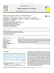
With the “window-on-world” metaphor, a planar display, such as a TFT-LCD monitor or a projection screen, becomes a window to the virtual scene (the world) being rendered. To accommodate for screen size and the viewer’s head position relative the screen, an off-axis projection matrix (Section 3.1.4) is generally required. Virtual objects may appear both in front of and behind the window. We have illustrated the metaphor for two common display configurations: a vertically mounted display (Figure 3.1a); and horizontally mounted (tabletop) display (Figure 3.1b). The metaphor is useful in stereo rendering because its projections preserve spatial properties in the scene and allow providing undistorted images from oblique viewing angles. It allows rendering correct stereo for planar displays, e.g., in “Fish Tank VR” [10] and in immersive VR environments such as CAVEs, when the viewer is head-tracked. 12
(a) symmetric frustum
(b) asymmetric frustum
Figure 3.2: Two types of view frustum used in perspective projection: (a) symmetric view frustum for regular on-axis projection; (b) asymmetric view frustum for off-axis projection.
3.1.4
Off-Axis Projections
Creating correct stereo parallax on planar 2D displays with the window-on-world metaphor requires asymmetric view frustums creating off-axis perspective projections [17]. A symmetric view frustum (for regular on-axis perspective projection) is shown in Figure 3.2b, whereas an asymmetric view frustum is shown in Figure 3.2a. OpenGL (which uses a right-handed coordinate system) uses the following matrix for perspective projection [18]1 : 2n r+l 0 0 r−l r−l 0 2n t+b 0 t−b t−b P= (3.1) 2f n , − 0 − ff +n 0 −n f −n 0 0 −1 0 in which l, r, b, t and n (left, right, bottom, top, and near, respectively) define the frustum’s near plane (projection plane), and f (far) also defines the frustum’s far plane, as seen in Figure 3.2a. The perspective projection P in Equation 3.1 is the product of a shearing matrix H, 1 0 r+l 0 2n 0 1 t+b 0 2n H= (3.2) 0 0 1 0 , 0 0 0 1 a scaling matrix S, −2n r−l
0 S= 0 0
0 −2n t−b
0 0
and a matrix for perspective normalization N, 1 0 0 0 1 0 N= 0 0 − f +n f −n 0 0 −1 1
0 0 1 0
0 0 , 0
(3.3)
1
0 0
n , − f2f−n
(3.4)
0
The fourth edition of Angel [18] states this matrix incorrectly. The correct matrix is found in the book’s errata.
13
(a)
(b)
Figure 3.3: Illustration of a homography (perspective transform) being applied to a rectangle: (a) before; (b) after. such that P = NSH.
(3.5)
After points are multiplied with P, the subsequent perspective division maps points that were inside the frustum onto normalized device coordinates. From P, it is possible to derive the following matrix P0 that takes the viewer’s eye position xeye = (xeye yeye zeye 1) and the physical screen dimension s = (sw sh ) into account and creates the required type of off-axis projection for the window-on-world: r0 +l0 2n 0 0 r0 −l0 r0 −l0 2n t0 +b0 0 0 0 −b0 0 t t0 −b0 (3.6) P = 2f n , 0 0 − ff +n −n − f −n 0 0 −1 0 in which l0 = r0 = b0 = t0 =
� n � sw − − xeye , zeye 2 � n � sw − xeye , zeye 2 � n � sh − − yeye , zeye 2 � � n sh − yeye . zeye 2
(3.7) (3.8) (3.9) (3.10)
Please see Bourke [17] for details. Points must also be translated with −peye before they are multiplied with P0 .
3.2
Homographies
A homograpy (in the context of computer graphics or computer vision) defines a mapping in the projective plane, such that for example 2D points x = (x y 1) (given in homogenous coordinates) in a rectangular area can be mapped on 2D points x0 = (x0 y 0 1) in a trapezoidal area, as shown in Figure 3.3. The word perspective transform is sometimes used instead of homograpy. On matrix form, the mapping becomes x0 = Hx (3.11) 14
(a)
(b)
Figure 3.4: Illustration of the underlying principles behind two common types of autostereoscopic displays: (a) parallax barrier; (b) lenticular sheet. The unknowns for the 3 × 3 matrix H in Equation 3.11 can be exactly determined (up to a scale factor) from eight equations (four point correspondences) [19]. After fixing the scaling factor, the matrix can be written as h11 h12 h13 H3×3 = h21 h22 h23 . (3.12) h31 h32 1 This will be used in a later chapter for keystone correction.
3.3
Autostereoscopic Displays
In order to show a stereoscopic image, traditional stereoscopic displays are either head mounted (HMD) or require the viewer to wear special glasses. This can make eye-contact in collaborative work around the display difficult. In HMDs, the presence of lag in the display or tracker device may also cause the viewer dizziness (sometimes referred to as simulator sickness). Autostereoscopic displays avoid the aforementioned problems by dividing the space in front of the display into viewing zones; when both eyes are in different viewing zones, the display can present separate images for the left and right eye. In the following sections, we review the principles behind two such display technologies: parallax barriers and lenticular sheets. We refer to Halle [3] for a more comprehensive overview of autostereoscopic displays.
3.3.1
Parallax Barriers
A parallax barrier display is constructed by placing a layer of thin opaque vertical stripes between the viewer and display’s pixel grid (see Figure 3.4a). Since the barrier will be visible to the viewer, the overall brightness of the display is reduced. Moreover, the display’s horizontal resolution is divided by the number of views the parallax barrier is designed for.
3.3.2
Lenticular Sheets
A lenticular sheet consists of small lenticular elements arranged into columns. The sheets are made of highly transparent materials, typically polycarbonate or, for higher quality lenticular sheets, crystal. Similar to a parallax barrier, the lenticular sheet is placed between the viewer 15
and the display’s pixel grid (see Figure 3.4b), and the horizontal resolution becomes divided by the number of views, i.e., the number of pixels per lenticular element. In contrast to a parallax barrier, however, a lenticular sheet does not significantly reduce the display’s brightness, since each lenticular element will be fully illuminated.
3.4
Head-Tracking
Using a tracking device to track the viewer’s head is referred to as head-tracking. From the tracking position and orientation, it is generally possible to establish the approximate location of the viewer’s pupils. This information may be used for rendering dynamic perspective, i.e., continuously updating the scene eye point so that it matches the current location of the viewer’s pupils. In order to render correct dynamic perspective, the tracking workspace must be properly registered with the virtual workspace, and the window-on-world viewing metaphor (Section 3.1.3) must be used. The quality of the dynamic perspective is limited by the accuracy and precision achievable with the tracking device, the marker types, the degrees of freedom (DOF) being tracked, and how accurately the tracking workspace can be registered with the visual workspace. Tracking rates about 60 Hz (or more) are also desirable to ensure smooth perspective updates. Finally, tracking latencies should be minimized, since they contribute to input lag; Ware et al. have shown that too much input lag in a display can impair task performance [20].
3.4.1
Tracking Devices
We will here review four types of tracking devices that are used for head-tracking. Typically, the devices track markers attached to the head; this type of tracking, in which stationary sensors and moving markers are used, is referred to as inside-out tracking. Optical trackers typically register light from the visible or infrared spectrum, or both. Tracking in the visible spectrum is often image-based, relying on computer vision algorithms and feature detection, e.g., of color or patterns in the sensor image. Tracking in the infrared spectrum simplifies the task of extracting good features considerably; markers emitting or reflecting infrared light may easily be segmented from the background, e.g., by thresholding and blob detection. IR LED markers (active markers) emit infrared light, whereas highly retro-reflective markers (passive markers) reflect infrared light and require an external illumination source. Accoustic trackers use sound for triangulating the location of markers. Frequencies in the ultra-sonic range make the sound inaudible for humans and minimize interference from the environment. Accoustic trackers are generally robust but are limited in accuracy and precision. Magnetic trackers use electromagnetic fields to locate markers and offer excellent robustness, accuracy, and precision. However, they have limited range and can be sensitive to interference from the environment, e.g., from metal objects and other sources of electromagnetic fields. Magnetic trackers may also be unsuitable for some environments, e.g., in hospitals where they might interfere with the medical equipment. Eye-trackers track the viewer’s pupils directly, without the use of markers. Commercial eyetrackers are available from, e.g., Tobii AB2 . In addition to providing a position of each pupil, eye-trackers also provide a gaze vector, i.e., the viewing direction. Despite being non-invasive, eye-trackers have a number of drawbacks that may render them unsuitable for head-tracking, such as a small working space, limited depth resolution, and difficulties in tracking pupils if a viewer wears glasses. 2
http://www.tobii.com. Accessed on October 30, 2011.
16
Chapter 4
3D Holographic Display The 3D holographic display prototype was developed at KTH [4, 5] and enables autostereoscopic viewing from multiple viewing angles. Furthermore, CBA uses two high-performance workstations to provide display outputs and rendering capabilities. An optical tracking system is also connected to one of the workstations via a serial RS-232 interface. Figure 4.2 in this chapter shows the physical setup of the holographic display.
4.1
Projectors and Holographic Optical Element
The holographic display prototype uses eight projectors mounted from the ceiling. The projectors are commercial off-the-shelf DLP-LED projectors from Benq, of model GP1, capable of providing SVGA resolution (800×600 pixels) at 60 Hz refresh rate. The projectors are carefully aimed at a special holographic optical element (HOE), shown in Figure 4.1b, that acts as a projection screen. This HOE will re-emit incoming light so that a narrow viewing slit is created for each projector’s image, as seen in Figure 4.1; this enables
(a)
(b)
Figure 4.1: (a) Illustration the viewing slits created by the 3D holographic display. The slitprojector correspondance is highlighted for the two center-most projectors. (b) Photo of the holographic optical element (HOE). 17
autostereoscopic viewing with the display. The HOE used in the display prototype only re-emits light from the red region of the visible spectrum; light from other regions of the spectra may still appear as reflections on the HOE’s glass surface, and must therefore either be filtered or masked out in software.
4.2
High-Performance Workstations
Two HP Z800-workstations provide display outputs for the eight projectors, as well as sufficient performance and rendering capabilities for driving these outputs, i.e., rendering a virtual 3D scene from multiple perspectives. Each workstation had been equipped with two NVIDIA Quadro FX 4800 GPUs providing four display outputs. A 100-MBit network also connected the workstations. Furthermore, one workstation is connected via parallel port interface to a PHANTOM Premium 1.5/6DOF HF (high-force model) haptic device from Sensable.
4.3
Optical Tracking System
The tracking system used with the 3D holographic display is a Precision Position Tracker (PPT) optical tracking system from WorldViz1 . This tracking system consists of four IR cameras, a calibration rig, markers, and a computer running Windows XP and the proprietary WorldViz PPT software. A graphics card from Matrox provides hardware accelerated blob detection to the system. After the tracking system is calibrated, it can track up to eight active IR LED markers at 60 Hz. Moreover, the system guarantees a maximal latency of 17 ms. The PPT software provides access to tracking data over the serial RS-323 interface via either VRPN or the special PPT API.
1
URL: http://www.worldviz.com. Accessed on October 30, 2011.
18
Figure 4.2: Photo of the 3D holographic display. The image shows: (A) the eight projectors and the projector rig; (B) the HOE; (C) the cameras in the optical tracking system; (D) the tracking calibration rig; (E) the computer for the optical tracking system; (F) and a PHANTOM haptics device. Note: the two workstations are missing in the image.
19
20
Chapter 5
Development of Rendering Software In this chapter, we describe the software we developed for this master’s thesis. The existing rendering software that CBA uses together with the 3D holographic display prototype does not (out-of-box) provide functionality for keystone correction, arbitrary off-axis projection matrices, or use of head-tracked (dynamic) perspective. We needed this functionality in order to accomplish two main objectives: • Calibrate the graphics-rendering pipeline for rendering accurate perspective with the 3D holographic display. • Use dynamic perspective to enable smooth view transitions and ensure that viewers always see a correct stereoscopic image on the HOE. We decided to develop a software library that extends the existing rendering software, a modified version of H3DAPI1 from SenseGraphics AB2 (Section 5.1), with components for per-view keystone correction, arbitrary off-axis projection matrices, and use of head-tracked perspective (Section 5.2). Furthermore, we developed a software tool (Section 5.3) that helps us find the perspective transforms that remove keystone distortion in projected images and make them coincide with the HOE.
5.1
H3DAPI
H3DAPI is an open source (GPLv2-licensed) cross-platform scene graph API providing graphics and haptics rendering of virtual 3D scenes described in the ISO standard XML-based X3D3 file format [21]. The API is implemented in C++ and uses OpenGL for graphics rendering. Haptic rendering is provided by a stand-alone haptic API (HAPI) supporting a large number of haptic devices, including the well-known PHANTOM devices from SensAble4 . A scene graph in H3DAPI is a hierarchical graph consisting of nodes and fields. Nodes may be divided into traditional node categories such as root nodes, group nodes, child nodes, or leaf nodes. A node may contain multiple fields, links to child nodes, and logic to, for example, draw geometric shapes, alter OpenGL states, or interface with hardware devices. Fields are data containers including the ability to execute custom logic when their values need to be updated from incoming data. H3DAPI also utilizes a routing network allowing fields to be routed to other fields, enabling data exchange between nodes. The scene graph is traversed in depth-first order and lazy evaluation is used for the field updates. 1
URL: URL: 3 URL: 4 URL:
2
http://www.h3dapi.org. Accessed on October 30, 2011. http://www.sensegraphics.com. Accessed on October 30, 2011. http://www.web3d.org/x3d. Accessed on October 30, 2011. http://www.sensable.com. Accessed on October 30, 2011.
21
(a) keystone effect
(b) short throw
Figure 5.1: (a) Illustration of keystone distortion caused by an oblique projector angle. (b) Illustration of short throw causing the projected image to become larger than the HOE. X3D is the highest level of programming in H3DAPI; it is used to set up new scene graphs, initialize field values, and add routes between fields. At the next intermediate programming level, Python is used to define new fields, add scripting and logic to the scene graph, and access functionality available in standard Python modules. At the lowest level, C++ is used to define new nodes and implement time-critical or computationally intensive tasks, e.g., simulations. CBA had (jointly with this thesis) modified H3DAPI (version 2.1.1) to sequentially render four views per dual-GPU workstation, for display on four display outputs connected to projectors. With H3DNetworkingUtils5 , a third-party network node library for H3DAPI, up to eight simultaneous views of a scene can be rendered and displayed by two workstations synchronised over a network connection. However, the synchronisation requires manually tailoring each scene graph for a master-slave configuration, something that can involve much extra work for existing H3DAPI applications.
5.2
Implementing a Node Library for H3DAPI
We implemented the following new nodes in our software library: • • • •
KeystoningPM—provides keystone correction via a single-pass method Keystoning—provides keystone correction via a two-pass method WoWViewpoint—sets up the view frustum for the window-on-world PPTTracker—receives tracking data from the optical tracker
5.2.1
Nodes for Keystone Correction
Because of oblique projector angles and short projector throw, the projected images suffered from keystone distortion (appeared trapezoidal instead of rectangular) and became larger than the size of the HOE. This is illustrated in Figures 5.1a and 5.1b. The projectors provided no lens-shifting capabilities that could rectify the distortion, and the digital keystone correction in the projectors was too limited to be used. Thus, we decided to implement our own softwarebased keystone correction via custom H3DAPI nodes (KeystoningPM and Keystoning). 5
URL: http://www.ict.csiro.au/downloads.php. Accessed on October 30, 2011.
22
Keystone distortion can be rectified by a perspective transform that provides a one-to-one mapping between points in the original image and points defined by the perspective transform (see Section 3.2). In a real-time rendering application, this transform must be carried out in every new frame being rendered. It would be possible to apply the transform on the CPU: for each new frame, the CPU would have to download the frame from GPU memory, apply the transform to it, and then upload it to GPU memory again in order to redraw it. However, each of these steps are expensive (particularly GPU-CPU transfers) and might cause a significant decrease in rendering performance. In order to maintain good rendering performance, we implement keystone correction so that it utilizes the GPU for transforming each view. The following methods are possible to implement in H3DAPI’s OpenGL-based rendering pipeline: 1. Manipulate OpenGL’s projection matrix stack to perform keystone correction on vertex level [8, 7]. 2. Render-to-texture and apply keystone correction as a post-processing step (on the rasterized frame). 3. Write a vertex shader that perform keystone correction on vertex level. The first method requires a single render pass and relies on manipulation of OpenGL’s projection matrix stack, which is part of the (now deprecated) OpenGL fixed function pipeline. The second method requires two render passes and relies on render-to-texture and perspective correct texture interpolation. The third method is equivalent to the first, but require the OpenGL programmable (shader-based) pipeline to be used instead. We decided to implement the first two methods in the above list in our library. The third method could break compatibility with some existing OpenGL code in H3DAPI or applications using H3DAPI; for this reason, we decided not to implement it. Single-Pass Method We implement the technique described by Bimber et al. [7] to perform keystone correction in a single render pass. This technique can be summarized as premultiplication of the projection matrix with an extended 4 × 4 matrix obtained from the 3 × 3 perspective transform H3×3 from Equation 3.12 in Chapter 3.2. As described by Bimber et al., the matrix H3×3 can be extended into the following 4 × 4 matrix: h11 h12 0 h13 h21 h22 0 h23 . H4×4 = (5.1) 0 0 1 0 h31 h32 0 1 It would now be possible to perform keystone correction of a scene by pre-multiplying the projection matrix P (see Equation 3.1 in Chapter 3.1.4) with H4×4 , i.e., H4×4 P. However, the perspective division from the perspective projection may produce z-values (depth values) outside the allowed range [−1, 1]. This means it would not be possible to use OpenGL’s built-in depth test (which is hardware accelerated) for rendering primitives in correct order. Bimber et al. suggest that H4×4 should be replaced with the following matrix: h11 h12 0 h13 h21 h22 0 h23 H0 4×4 = (5.2) 0 0 1 − |h31 | − |h32 | 0 h31 h32 0 1 23
/* Single - Pass Keystone Correction */ // Pre - multiply current projection matrix with the // perspective transform ( homograhpy ) glMatrixMode ( GL_PROJECTION ); GLfloat projection [16]; glGetFloatv ( GL_PROJECTION_MATRIX , projection ); glLoadMatrix ( homography ); glMultMatrixf ( projection ); glMatrixMode ( GL_MODELVIEW ); // Render the scene scene - > render (); Listing 5.1: Pseudocode for single-pass keystone correction.
This matrix H0 4×4 gives approximate depth values in the range [−1, 1], thus enabling us to use OpenGL’s standard depth test. We implemented the above single-pass technique for keystone correction in a custom H3DAPI node (KeystoningPM) inheriting from H3DAPI’s H3DMultiPassRenderObject class. The H3DMultiPassRenderObject class provides multi-pass rendering capabilites with H3DAPI and declares three virtual class methods an inheriting class may choose to implement: • renderPreViewpoint—called before the projection matrix and eye point are set up • renderPostViewpoint—called before the scene is rendered • renderPostRendering—called after the scene has been rendered Our node class implements the renderPostViewpoint, which it uses to first select the correct perspective transform (for the projector the view is being rendered for) from a list of transforms, and then manipulate the projection matrix stack according to Listing 5.1. During the first scene graph traversal, the perspective transforms will be loaded from file into system memory.
Two-Pass Method Render-to-texture is the standard method to perform real-time post-processing effects on the GPU. In OpenGL 2.1, render-to-texture is supported via the GL_EXT_framebuffer_object extension [22]. This extension provides framebuffer objects (FBOs) allowing textures to be used as rendering destinations. For a good introduction to the usage of FBOs, please see Persson [23]. Keystone correction as a post-processing step can be performed by first rendering to an FBO, followed by multiplying the current modelview matrix with the perspective transform and finally drawing a screen-filling quadrilateral textured with the FBO’s color attachment. The pseudocode in Listing 5.2 describes this method. We implement the above two-pass technique for keystone correction in a custom H3DAPI node (Keystoning) inheriting from the same base class as our previous KeystoningPM node. The node implements renderPostViewpoint, in which we bind the FBO, and renderPostRendering, in which we draw the screen-filled quadrilateral with the FBO’s texture. For the latter operation, we use standard bi-linear texture filtering. 24
/* Two - Pass Keystone Correction */ // Perform render - to - texture fbo - > bind (); scene - > render (); fbo - > unbind (); // Post - multiply current model - view matrix with // the perspective transform ( homography ) glMatrixMode ( GL_MODELVIEW ); glMultMatrixf ( homography ); // Draw screen - filling quad textured with the // FBO ’s color attachment fbo - > draw (); Listing 5.2: Pseudocode for two-pass keystone correction.
Method Validation After implementing both keystone correction methods, we validated the implementations by rendering identical test-scenes for both nodes and comparing the results (see Figure 5.2) with a ground truth correction. Both method applied the keystone correction correctly; however, the rendering results were not identical, as can be seen in Figures 5.2d–5.2e, where, for example, identical lines in the two images show different types of aliasing. This is because the first method applies the transform at individual vertices, while the second method applies the transform at pixels in the final rasterized image (a minification operation).
(a) uncorrected test scene
(b) single-pass method
(d) close-up of (b)
(c) two-pass method
(e) close-up of (c)
Figure 5.2: Visual comparison of the keystone correction methods we implemented for H3DAPI: (a) the uncorrected scene; (b) keystone correction applied with the single-pass method; (c) keystone correction applied with the two-pass method; (d) close-up of (b); (e) close-up of (c). 25
/* Off - Axis Projection for Window - on - World */ // Setup asymmetric view frustum glMatrixMode ( GL_PROJECTION ); glLoadIdentity (); glFrustum (( clip_near / eye . z ) * ( -( screen_width / 2) - eye . x ) , ( clip_near / eye . z ) * ( screen_width / 2 - eye . x ) , ( clip_near / eye . z ) * ( -( screen_height / 2) - eye . y ) , ( clip_near / eye . z ) * ( screen_height / 2 - eye . y ) , clip_near , clip_far ); // Setup camera viewpoint ( scene eye point ) glMatrixMode ( GL_MODELVIEW ); glLoadIdentity (); glTranslatef ( - eye .x , - eye .y , - eye . z ); Listing 5.3: Pseudo-code (C++-style) for setting up the off-axis projection.
5.2.2
Node for Arbitrary Off-Axis Projection
Before rendering a scene, H3DAPI calls the active viewpoint node’s setupProjection method to set up the OpenGL projection matrix. H3DAPI then initializes the OpenGL modelview matrix to correspond to a translation with the inverted eye position. We created a new viewpoint node class (WoWViewpoint) that implements setupProjection so that the method calculates and uses the parameterized off-axis projection matrix for the window-on-world (see Chapter 3.1.4). We added a new field that can be used to specify physical screen size (width and height in meters). By default, this field is set to the size of the HOE. Listing 5.3 shows the pseude-code for how the projection matrix and modelview matrix is set up after our WoWViewpoint node has been added to the scene graph.
5.2.3
Node for Head-Tracking
To enable the use of dynamic head-tracked perspective with H3DAPI and the 3D holographic display, we extended H3DAPI with a node for receiving head-tracking data. This node (PPTTracker) continuously receives the position of an IR LED marker from the tracker and transforms this position from the tracking reference frame into a screen reference frame. Furthermore, the node exposes a position field that other nodes in the scene graph may route from. To access the tracking data from the optical tracking system (Section 4.3), we used WorldViz’s PPT developer’s API6 . This API is implemented in C++ and allowed our node to connect to the tracking computer and receive tracking data over a serial RS-232 interface. In order to avoid the main H3DAPI thread being blocked each time our node received a new position from the tracker, we implemented the receiving part in a separate thread and used mutex locking for safely transferring values between the threads; we used POSIX threads (Pthreads) for thread creation and mutex synchronisation. In addition, using a separate thread allowed us to use receiving rates independent of the graphics rendering rate. By routing from the position field in PPTTracker to the relPos field in our WoWViewpoint node, the current viewpoint is updated each new scene graph traversal. We also had to disable 6
URL: http://www.worldviz.com/products/ppt/development.html. Accessed on October 30, 2011.
26
H3DAPI’s built-in scene navigation, and set the followViewpoint field in haptic device nodes to false, in order to get the perspective to update correctly.
5.2.4
Compilation into a Dynamic Linked Library
H3DAPI allows new nodes to be compiled into shared libraries that H3DAPI can load dynamically at run-time with its ImportLibrary node; this way, the nodes become available in the scene graph. We gathered the nodes we developed into a single library and used CMake7 to create build files for this library. Only small amounts of platform-specific code (added via compiler preprocessor directives) was needed to make the library compile on both 32-bits Windows 7 (using Visual Studio 2010) and 64-bits RHEL 5.5 (using GCC and Makefiles).
5.3
Software Tool for Finding Perspective Transforms
In order to use the keystone correction nodes we developed in Section 5.2.1, we needed to provide the nodes with perspective transforms for all the projectors in the 3D holographic display. As we noted in Chapter 3.2, the 3 × 3 matrix defining such a perspective transform can be determined (up to a scale factor) from four point correspondences (eight points). We wrote a small program allowing us to manually set up these point correspondences for each projector; the program will also compute the homographies. To find the perspective transform for a particular projector, the user of the program has to move four markers (initially positioned at the corners of the projector image) so that they coincide with the HOE’s four corners. The program then uses the cvGetPerspectiveTransform function from the OpenCV-library8 to compute a perspective transform from the pointcorrespondences. We refer to Bradski et al. [19] for a description of this function, which can also provide least-square estimates of the perspective transform if more than four pointcorrespondences are used. We implemented a preview function using one of the methods described in Section 5.2.1; this preview function allowed us to inspect the result of a perspective transform. For more detailed usage-instructions for this tool, we refer to our description of the calibration procedure in Chapter 6.
7 8
URL: http://www.cmake.org. Accessed on October 30, 2011. URL: http://opencv.willowgarage.com/wiki/. Accessed on October 30, 2011.
27
28
Chapter 6
Calibration Before we use the extended graphics rendering pipeline provided by the nodes we developed in Chapter 5, we first need to calibrate the projectors and obtain the perspective transforms for keystone correction, so that static perspective views will render correctly. Furthermore, in order to set up the dynamic perspective correctly, we need to calibrate the tracking system and register the tracking workspace with the visual workspace.
6.1
For Static Perspective
For the projector calibration, we use a simple cross-pattern to show each projector’s center-ofprojection and image orientation. Because of how the HOE creates its slit plane, the projectors must be carefully spaced and aimed at the HOE. This was already done once, during the installation of the display. What remain is to fine-tune the individual focus and angle of each projector. We configure both workstations to show the cross-pattern (as desktop wallpaper) on all projectors. Before a new calibration, we let the projectors run for a while, until they obtain stable focus and image. One projector is selected as the reference projector. We then calibrate the projectors with the following steps:
(a)
(b)
Figure 6.1: Photos showing the projector calibration: (a) we have calibrated the center-ofprojection and image orientation for the first projector; (b) we have calibrated the center-ofprojections and image orientations of three more projectors. 29
(a)
(b)
(c)
Figure 6.2: Photos showing how we obtain the perspective transforms for keystone correction: (a) the initial calibration scene for one of the projectors; (b) we have moved one corner of the scene’s quadrilateral to the corresponding corner on the HOE; (c) we have moved the remaining corners to their corresponding corners on the HOE and applied the perspective transform to the program’s test pattern (displayed on a paper overlay placed on the HOE). 1. Blank all projectors, except the reference projector. 2. Calibrate the reference projector according to Figure 6.1a, so that its cross intersects with the center markings along the HOE’s edges. 3. For remaining projectors: (a) Unblank the projector and calibrate it according to Figure 6.1b, so that its cross closely matches the reference projector’s. To obtain the perspective transforms for rectifying the keystone distortion in the projector images and scale them to the same size as the HOE, we use the projector calibration software we developed in Chapter 5.3. The program starts by loading the most recent calibration (if one is available) and displays the calibration scene (Figure 6.2a) for the first projector (Chapter 4) connected to the computer from which we run the software. We then find the perspective transforms with the following steps: 1. For each projector: (a) Pick one of the corners and move it (with the mouse) to a corresponding corner on the HOE (Figure 6.2b). (b) Repeat for the other corners (Figure 6.2c). (c) Compute the transform and save it. (d) Switch to next projector. The calibration program has a test pattern we use during the calibration to inspect the computed perspective transforms. A paper overlay placed on the HOE allows us to compare the transformed pattern with reference markings on the overlay (see Figure 6.2c).
6.2
For Dynamic Perspective
We calibrate the tracking system with the following steps: 1. Place the tracking system’s calibration rig so that its center and orientation match the HOE’s (Figure 6.3). 2. Run the PPT software and ensure that all cameras have a clear view of the calibration rig’s four IR LEDs, and are aimed at the region where the viewer’s head will be in front of the display. 30
Figure 6.3: Placement of the calibration rig during calibration of the tracking space. 3. Adjust each cameras’s sensitivity and threshold parameters (with the histograms that the PPT software provides). 4. Run the calibration wizard. This will automatically calibrate the tracking space. If we get interference from ambient IR-light or marker reflections, we make use of the PPT software’s built-in mask tool to subtract sensor regions during the calibration. Next, in order to register the tracking workspace with the visual workspace, we must convert all tracking vectors in the tracker’s reference frame into new vectors in the screen’s reference frame. The conversion between two reference frames can be described by a change of basis, followed by a translation. Let A and B be two right-handed reference frames in R3 , R the 3 × 3-matrix describing the relative rotation between A and B, T the 3 × 4-matrix describing the translation defined by the relative offset between A’s and B’s origins, and v some vector given in A. The transform of v from A to B begin with the change of basis m11 m21 m31 xv xv 0 v0 = M−1 v = MT v = m12 m22 m32 yv = yv0 , m13 m23 m33 zv zv 0
(6.1)
where M is
r11 r12 r13 1 0 0 m11 m12 m13 M = RI = r21 r22 r23 0 1 0 = m21 m22 m23 , r31 r32 r33 0 0 1 m31 m32 m33
(6.2)
and M−1 = MT follows from M being orthogonal. The new vector w, corresponding to v in B, is now obtained by the equation v 0 � 0� 1 0 0 tx x w vy 0 x v w=T = 0 1 0 ty = wy . vz 0 1 wz 0 0 1 tz 1
(6.3)
For the tracking space we obtain from placing the tracking system’s calibration rig as in Figure 6.3, the change of basis is accomplished by swapping the y and z coordinate axes. To compensate for the 3 cm vertical offset between origin in tracking space and the HOE’s surface, we translate all vectors in the new basis by 3 cm along the negative z coordinate axis. 31
(a)
(b)
Figure 6.4: Calibration result: (a) four views of a 3D object, rendered with keystone correction and off-axis projections, and from identical vantage points; (b) the four views rendered from different vantage points, corresponding to a 6.0 cm IPD. The views are shown on a paper sheet overlay placed on the HOE.
6.3
Calibration Results
After the calibration, H3DAPI was able to render static perspective views with both keystone correction and correct off-axis projections when using the nodes from our software library. Figure 6.4a shows four static perspective views (showing a 3D object casting its shadow on the HOE) rendered from the same vantage point and projected on the HOE. Figure 6.4b shows the same views but rendered from different vantage points, so that the eye point separation matches a 6 cm IPD. Furthermore, H3DAPI was able to render correct dynamic perspective for monoscopic viewing (views rendered as in Figure 6.4a). In Chapter 7, we describe our experiments with enabling dynamic perspective also with stereoscopic viewing. A separate master’s theis project conducted at CBA evaluated the visual quality of the 3D holographic display prototype [13]. In that evaluation, a more formal validation of the static and dynamic perspective was conducted. To validate the dynamic perspective, a high-precision manufactured metal wirecube was placed on the HOE, so that the overlap between a rendered wirecube and the physical wirecube could be visually inspected.
32
Chapter 7
Experiments In this chapter, we describe our experiments with enabling correct stereo viewing and smooth view transitions for the dynamic perspective mode of which implementation and calibration we described in Chapters 5 and 6.
7.1
View Update Schemes
As we reported in Chapter 6.3, we can use dynamic perspective with monoscopic viewing after the rendering pipeline and display are calibrated. However, we want to enable this dynamic perspective mode to work also with stereo and, furthermore, enable smooth view transitions when the viewer’s eyes move between slits in the display. Assuming the interpupillary distance (IPD) and the display slit width are the same, when an eye moves into a new slit, the ownership for the view/slit should change so that the new owner is the eye that has just entered. This is illustrated in Figure 7.1. Under these conditions, for a single viewer, only two views need to be kept updated. Because pupils have a diameter of about 2 mm (under normal bright conditions), a small flicker in the perspective may be visible when the change in ownership occurs. However, the large variance in the IPD among individuals means that a viewer’s IPD is unlikely to be the same as the slit width [16]. When the IPD is smaller than the slit width, both eyes’ pupils may end up in the same slit, so that the viewer perceives a monoscopic image. This is illstrated in (Figure 7.2). When the IPD is larger than the slit width, it is no longer sufficient to keep only two views updated.
(a)
(b)
(c)
Figure 7.1: Image sequence illustrating how the ownership for a particular view/slit need to change when both eyes leave their slits: (a) the initial state; (b) the state shortly before both eyes leave their slits; (c) the new state immediately after. 33
(a)
(b)
(c)
Figure 7.2: Image sequence illustrating how monoscopic viewing can occur when the viewer’s IPD is smaller than the display’s slit width: (a) initial state, in which the viewer perceives correct stereo; (b) the viewer’s eyes are in the same slit, causing monoscopic viewing; (c) the sudden change in perspective (while the eyes are still in the same slit) that both eyes perceive as “flicker”.
(a)
(b)
(c)
Figure 7.3: Image sequence illustrating the three-view update scheme that should ensure correct stereo and smooth view transitions for all IPDs larger than the slit width: (a) initial state; (b) state updated; (c) state updated again. Dodgson [11] suggest that for a theoretical head-tracked multiview displays of similiar characteristics as the display prototype we use, a three-view update scheme (Figure 7.3) should be sufficient to always render correct perspective for both eyes and accomodate for normal variations in IPD. This scheme is illustrated in Figure 7.3. The HOE in the display prototype was designed to create 5 cm wide slits, which would allow the three-view update scheme to be used.
7.1.1
Implementing the Three-View Update Scheme
Implementing the three-view update scheme for the dynamic perspective mode only required minor changes to the existing nodes in our library.
7.1.2
Finding Viewing Slit Boundaries
In order to adapt the three-view update scheme implementation for the display prototype’s viewing slits, we need to know (with reasonable accuracy) where in the display’s slit plane the slit boundaries are located, so that we can include this information in the update scheme. Since we did not have such knowledge, we devised a method for mapping out the location of the slit boundaries. We set up the experiment scene shown Figure 7.4. The scene show different patterns for 34
(a)
(b)
(c)
Figure 7.4: The experiment scene we used together with tracking to determine the locations of slit boundaries in the slit plane: (a) illustration of the scene, showing views 1 and 2 as they would appear from a non-boundary location (“z=X.XX” is used to display current tracking z); (b) illustration of the same scene, but here showing the views as they would appear near a boundary location; (c) the HOE (showing the experiment scene) photographed near a slit boundary.
(a)
(b)
Figure 7.5: 2D-illustration of viewing zones (for the four center-most view-slit pairs) above the HOE’s slit plane: (a) viewing zones in which some part of a corresponding view is visible (the boundaries and lines-of-sight for one of the viewing zones are drawn in bold to better illustrate the zone’s shape); (b) viewing zones in which the center of a corresponding view is visible. Notice the overlap that exists between the zones in (a). different view/slit pairs; by holding a marker device close to the eye and, from a height slightly above the slit plane (known to be located about 40 cm above the HOE), logging positions from which the intersection between two patterns appear at the center marking, we obtain a map of the boundaries. The result is seen in Figure 7.6. After we obtained the initial slit boundary map, we fitted lines (using linear regression) to the observations, so that each boundary could be described by a function. Because the display creates viewing zones some distance above the slit plane (see Figure 7.5), in which individual images may still be provided for the left and right eyes, we attempt to map out those boundaries as well. To obtain a map of the boundaries illustrated in Figure 7.5b, we use the same experiment scene but now log positions from different height levels. The result is seen in Figure 7.7.
35
Top View
0.1
0.7
0.2
0.6
0.3
0.5
0.4
0.4
0.5
0.3
0.6
0.2
0.7
0.1
0.80.4
0.3
0.2
0.1
0.0 x
Side View
0.8
z
y
0.0
0.1
0.2
0.3
0.00.8
0.4
(a)
0.7
0.6
0.5
0.4 y
0.3
0.2
0.1 0.0
(b)
3D View Front View
0.8 0.7
0.7 0.6 0.5 z 0.4 0.3 0.2 0.1
0.6
z
0.5 0.4 0.3 0.2 0.1 0.00.4
0.3
0.2
0.1 0.0 x
0.1
0.2
0.3
0.3 0.2 0.1 0.0 0.1 x 0.2 0.3
0.4
(c)
0.1 0.2 0.3 0.4 y 0.5 0.6 0.7
(d)
Figure 7.6: 3D-plot showing the initial map of the slit boundaries in the display prototype’s slit plane: (a) top view; (b) side view; (c) front view; (d) 3D view. Coordinates are tracking coordinates, where origin represents the HOE’s center.
36
Top View
Side View
0.1
0.5
0.2
0.4
0.3
0.3
z
y
0.0
0.4
0.2
0.5
0.1 0.2
0.1
0.0 x
0.1
0.0
0.2
0.5
0.4
(a)
0.3 y
0.2
0.1
0.0
(b)
3D View Front View 0.5
0.5 0.4 z
0.4 z
0.3 0.3
0.2 0.1
0.2 0.1 0.0
0.2 0.2
0.1
0.0 x
0.1
0.2
(c)
0.1
0.0
x 0.1 0.2
0.5
0.4
0.1 0.2 0.3 y
(d)
Figure 7.7: 3D-plot showing the map of the boundaries of the viewing zones (for four of the slits) extruding above the slit plane: (a) top view; (b) side view; (c) front view; (d) 3D view. The color of each boundary point indicates which slit boundary it belongs to. Coordinates are tracking coordinates, where origin represents the HOE’s center.
37
38
Chapter 8
Results With the rendering pipeline and display calibrated according to the steps outlined in Chapters 5 and 6, we are able to render static perspective views with keystone correction and correct offaxis projections for all projectors. The addition of head-tracking enabled correct dynamic perspective with monoscopic viewing (same vantage point used in all views). After we implemented the three-view update scheme and measured the slit boundaries and viewing zones in the display, a viewer wearing an infrared LED marker attached to a pair of glasses could see dynamic perspective with stereo when both eyes were located in different slits. But a viewer with 6.3 cm IPD (same as as the mean IPD [16]) could still perceive a certain non-smoothness (a flicker between two perspectives) near the slit boundaries during view transitions. Our measurements of the slits created by the display prototype indicate that the slits are about 5–7 cm wide in the slit plane (located about 40 cm above the HOE), with the slit width increasing along the direction towards us in the plane. Above the slit plane, the corresponding viewing zones for view/slit pairs quickly become wider than the slits in the plane, as seen in Figure 7.7 in Chapter 7.1.2. None of the two keystone correction methods we implemented had any significant negative impact on the rendering performance. Both methods provided equivalent transforms for the same projector images. However, because the first method (matrix stack manipulation) applies the transform to vertices, whereas the second (render-to-texture based) method applies it to the rasterized frame, there were some visible differences in the final rendering, as can be seen in Figure 5.2b–5.2c in Chapter 5.2.1. We observed that, once adjusted, the projectors in the display needed a significant amount of time (about 15 minutes) to obtain focus. Moreover, the focus did not remain stable over time. A projector could also shift its image several millimeters between sessions, which required us to readjust the projector angle and obtain a new perspective transform for this projector. Finally, when a virtual object was co-located with a physical reference object (placed on top of the HOE), we could observe a slight visual delay between the virtual and physical objects during head movements. This delay was mainly caused by input lag in the display [13].
39
40
Chapter 9
Summary and Conclusions 9.1
Summary
In this master’s thesis, we have developed a software library that allows an existing rendering software (H3DAPI) to render accurate perspective for the 3D holographic display at CBA, so that it may be used for its intended purpose: co-located haptics. More specifically, we have implemented methods for removing keystone distortion in the display’s projectors, calibrated the rendering pipeline with proper off-axis perspective projections, and added head-tracking and dynamic viewing. To experiment with enabling stereoscopic viewing and smooth view transitions with the dynamic viewing mode, we have measured the viewing slits created by the display’s holographic optical element and implemented a three-view update scheme that should ensure both eyes always see correct perspectives for stereo.
9.2
Conclusions
The calibrated rendering pipeline we obtain is necessary for rendering correct stereo for the 3D holographic display. Other rendering software would need similar modifications in order to render their content correctly for this type of display. Both of the keystone correction methods we implement work well for the task of rectifying the projected views. For scenes that use different projection matrices for different parts of the scene, it would probably be more convenient to choose the render-to-texture based method, since it does not involve modifying the projection matrix. Because the projectors in the display do not maintain stable focus over time, and also can shift their images several millimeters, the frequent need for re-calibration becomes tedious. In future generations of the display, we would wish for projectors with more reliable focus and better optics. Dynamic perspective can clearly improve the viewing experience for this type of display. We obtain limited motion parallax and can see correct stereo when both eyes are located in different slits. But continuous stereoscopic viewing and smooth view transitions are not possible with the current display prototype: the viewing slits in the display are too wide for people with normal IPD, and monoscopic viewing can occur at certain viewing angles. Thus, our conclusion is that future prototypes of the display would benefit from using narrower slits. Moreover, the display prototype has some display artifacts, such as dark banding appearing near the slit boundaries [13], which could also affect the perceived smoothness of view transitions. Other benefits of using dynamic perspective include allowing a variable IPD (instead of a fixed IPD same as the slit width) to be used with the display. For a single head-tracked viewer, 41
it becomes unnecessary to update views that are not visible from the viewer’s current head position; thus, the use of dynamic perspective provides a simple rendering optimization that can reduce the overall rendering complexity. Finally, there are a number of limitations and issues with the current head-tracking method we use: first of all, it only provides 3DOF head-tracking (position), which does not allow us to compensate for head rotations (a fixed head orientation is assumed when estimating the position of the pupils); second, the viewer has to wear an infrared LED marker attached to a pair of glasses, which somewhat contradicts the purpose of using an autosteroscopic display in the first place.
9.3
Future Work
Performing similar experiments with a HOE using narrower viewing slits could be of interest, to see whether it would allow continuous stereoscopic viewing and smooth view transitions. Such experiments could also be helpful for determining an optimal slit width that creates viewing zones small enough to accommodate for the variance in IPD among individuals. Adding 6DOF head-tracking (tracking orientation, in addition to position) to the display could provide a more accurate estimate of the position of the viewer’s pupils and allow us to render vertical parallax. To avoid the need for glasses (or similar headgear) for attaching markers to, it could also be appropriate to evaluate less invasive (marker-less) head-tracking methods, for example camera-based face-tracking. During the project, we got some ideas about how to further improve the image quality of the display: trilinear texture filtering (mip-mapping), or more advanced sampling methods [24], could reduce aliasing artifacts from the keystone correction; also, gamma correction and tone mapping could make better use of the dynamic range available in the display. To simplify the calibration task, camera-based methods could also be employed for automatically finding the corners needed for computing the perspective transforms for keystone correction [9].
42
Acknowledgments I am grateful to my supervisors Robin Strand1 , Martin Ericsson1 , and Ingrid Carlbom1 who all provided valuable help and feedback, as well as gave me the opportunity to work on this project. I would also like to thank Jonny Gustafsson2 for assistance with the 3D holographic display and for sharing technical information on how it works. Furthermore, I would like to thank Stefan Seipel13 for fruitful discussions, and the University of G¨avle for allowing us to borrow their tracking system. Also, a thanks to my co-workers Pontus Olsson1 and Jim Bj¨ork1 , as well as the rest of the CBA staff, for making my time at CBA enjoyable. Finally, a thanks to my brother Johan Nysj¨ o1 for helping with proofreading.
1
Centre for Image Analysis, Uppsala University Royal Institute of Technology 3 University of G¨ avle 2
43
44
References [1] L. Lipton, StereoGraphics Developers’ Handbook. StereoGraphics Corporation, 1997. [2] K. W. Arthur, K. S. Booth, and C. Ware, “Evaluating 3D Task Performance for Fish Tank Virtual Worlds,” ACM Transactions on Information Systems, vol. 11 no. 3, pp. 239–265, 1993. [3] M. Halle, “Autostereoscopic Displays and Computer Graphics,” in Computer Graphics, ACM SIGGRAPH 97 Proc., pp. 58–62, 1997. [4] J. Gustafsson and C. Lindfors, “Development of a 3D interaction table,” in Stereoscopic Displays and Virtual Reality Systems XI, Proc. of SPIE, vol. 5291, pp. 509–516, 2004. [5] J. Gustafsson, C. Lindfors, L. Mattson, and T. Kjellberg, “Large-format 3D Interaction Table,” in Stereoscopic Displays and Virtual Reality Systems XII, Proc. of SPIE, vol. 5664, pp. 589–595, 2005. [6] M. Ikits, C. D. Hansen, and C. R. Johnson, “A Comprehensive Calibration and Registration Procedure for the Visual Haptic Workbench,” in Proceedings of the workshop on Virtual environments 2003, pp. 247–254, ACM, 2003. [7] O. Bimber and R. Raskar, “Chapter 5: Creating Images with Spatial Projection Displays,” in Spatial Augmented Reality Merging Real and Virtual Worlds, pp. 111–125, A K Peters LTD, 2005. [8] S. Seipel and M. Lindkvist, “Methods and Application of Interactive 3D Computer Graphics in Anthropology,” tech. rep., Uppsala University, 2002. [9] T. Annen, W. Matusik, H. Pfister, H. Seidel, and M. Zwicker, “Distributed Rendering for Multiview Parallax Displays,” in Stereoscopic Displays and Virtual Reality Systems, Proc. of SPIE, vol. 5962, pp. 1–10, 2006. [10] C. Ware, K. Arthur, and K. S. Booth, “Fish Tank Virtual Reality,” in Proceedings of the INTERACT ’93 and CHI ’93 conference on Human Factors in Computing Systems, CHI ’93, pp. 37–42, ACM, 1993. [11] N. A. Dodgson, “On The Number of Viewing Zones Required for Head-Tracked Autostereoscopic Display,” in Proc. of SPIE, vol. 6055, 2006. [12] A. Boev, M. Georgiev, A. Gotchev, and K. Egiazarian, “Optimized Single-Viewer Mode of Multiview Autostereoscopic Display,” in Proc. of EUSIPCO 2008, August, Lausanne, Switzerland, 2008. [13] J. Bj¨ork, “Evaluation of a Holographic 3D Display,” Master’s thesis, Uppsala University, Sweden, 2010. 45
[14] G. S. Hubona, P. N. Wheeler, G. W. Shirah, and M. Brandt, “The Relative Contributions of Stereo, Lighting, and Background Scenes in Promoting 3D Depth Visualization,” ACM Transaction on Computer-Human Interaction, vol. 6 no. 3, pp. 214–242, 1999. [15] J. Pfautz, Depth Perception in Computer Graphics. PhD thesis, University of Cambridge, 2000. [16] N. A. Dodgson, “Variation and extrema of human interpupillary distance,” in Proc. of SPIE, vol. 5291, pp. 36–46, 2004. [17] P. Bourke, “3D Stereo Rendering Using OpenGL (and GLUT).” http://paulbourke.net/ miscellaneous/stereographics/stereorender, 2002. Accessed on October 30, 2011. [18] E. Angel, Interactive Computer Graphics: A Top-Down Approach using OpenGL. AddisonWesley, 4th ed., 2005. [19] G. Bradski and A. Kaehler, Learning OpenCV: Computer Vision with the OpenCV Library. O’Reilly, 2008. [20] C. Ware and R. Balakrishnan, “Reaching for Objects in VR Displays: Lag and Frame Rate,” ACM Transactions on Computer-Human Interaction (TOCHI), vol. 1, no. 4, p. 356, 1994. [21] H3DAPI, http://www.h3dapi.org, SenseGraphics AB. Accessed on October 30, 2011. [22] GL_EXT_framebuffer_object, http://www.opengl.org/registry/specs/EXT/ framebuffer_object.txt, Misc. vendors. Accessed on October 30, 2011. [23] E. Persson, “Framebuffer Objects.” White paper, http://developer.amd.com/media/ gpu_assets/FramebufferObjects.pdf, ATI Technologies, 2005. Accessed on October 30, 2011. [24] M. Pharr and G. Humphreys, “Chapter 11: Texture,” in Physically Based Rendering: From Theory to Implementation, pp. 485–568, Morgan Kaufmann, 2004.
46