Repository Support for the Virtual Software. Enterprise .... to DHT objects: create, delete, read, and up- date an ... remote nodes and links, approaches that of.
Repository Support for the Virtual Software Enterprise John Noll and Walt Scacchi Information and Operations Management Dept. University of Southern California Los Angeles, CA 90089-1421
Abstract
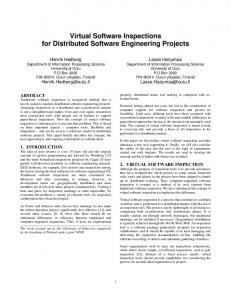
ploy a set of development tools to create and evolve software artifacts1 that are stored in a central repository, which serves as the medium for sharing artifacts among engineers and programmers. Software development in the future will likely take place in an environment that is much di�erent from this model. Software development teams will be highly decentralized, both physically and organizationally. Software will be produced by loosely coupled, \virtual enterprises," composed of developers from di�erent companies who cooperate on speci�c projects, then disband to form new alliances for other projects. Participants in these virtual enterprises will retain a high degree of autonomy over their own activities, environments, and data. Nevertheless, they will need to share artifacts with other members, such as requirements, project plans, source code, test results, deliverables, process models, and the relationships among them. Figure 2 depicts an example of a \typical" future development scenario. A loose collaboration among a customer, consultant, vendor, and software contractor is formed to enhance a legacy system. Each has its own internal tools and data, and each will require access to at least part of the others' data. Additionally, each will need to update and
Software development in the future will conducted by \virtual enterprises," consisting of loosely-coupled, widely distributed, autonomous development teams. Due to geographic separation and the loose cooperative structure of a virtual enterprise, each team will be highly autonomous, managing its own computing environment and tools. Thus, there will be no shared �lesystem or database to serve as an integrating resource. Similarly, we cannot assume that all teams will agree to adopt and use any one team's object storage manager or data model. Nonetheless, it will be necessary for each team to be able to modify jointly developed documents or process models. This papers presents a hypertext-based solution called \DHT" that supports software engineering data modeling and management, provides transparent access to heterogeneous, autonomous legacy repositories, and enables an implementation strategy with low cost and e�ort. In addition, we show how DHT solves the practical problems of sharing data in a virtual enterprise, integrating existing tools and environments, and enacting software processes.
1 Introduction
Contemporary software development 1 The term \software artifact" refers to the docenvironments follow the architectural model uments, programs, executables, etc. that form the shown in Figure 1: software engineers em- results of the software engineering process 1
A Virtual Software Enterprise
Consultant Chicago
Customer Los Angeles
(IN−PACKAGE ’CRL−USER) ;; −−−−−−− Level 0 −−−−−−−− (DEFSCHEMAD ANALYZE (INSTANCE TASK−CHAIN)) ;; −−−−−−− Level 1 −−−−−−−− (DEFSCHEMAD UNDERSTAND−REQUIREMENTS (INSTANCE ACTIVITY)) (ADD−VALUE ’UNDERSTAND−REQUIREMENTS ’TASK−FORCE−COMPONENT−OF ’ANALYZE))
|Project|Form|Module | +−−−−−−−+−−−−+−−−−−−−+ |Sim |Code|sim.exe| |Sim |Code|sim.obj| |Sim |Code|sim.c | |Sim |Code|sim.h | |Sim |Req |req |
?
Vendor Austin Software Contractor /
Bombay Sim−UI−Proj
RCS
UI
glue.obj
ui.c
ui.h
ui.obj
glue.c,v
Figure 2: A virtual software enterprise. expand the set of artifacts that represents the project's output and deliverables. Due to geographic separation and the loose cooperative structure, each team will be highly autonomous, managing its own computing environment and tools. Thus, A B C there will be no shared �le-system or database to serve as an integrating resource. Similarly, we cannot assume that all teams will agree to adopt and use any one team's object storage manager or data model. Nonetheless, it will be necessary for each team to be able to modify jointly developed documents or process models. The virtual enterprise produces a set of shared artifacts, but does not have a central repository where they can be stored. Without a shared database, how can participants retrieve and modify shared objects? This is Figure 1: Software development environment the problem addressed by this paper: how architecture. to enable sharing of software artifacts among autonomous, distributed development teams, given the absence of a shared repository. A solution must meet the following goals: Developers
Tools
Object Management Service (LAN Based)
Storage Manager
2
1. Model software artifacts, versions, and other relationships. 2. Provide transparent access to artifacts and relationships in heterogeneous, autonomous legacy repositories. 3. Preserve the local autonomy of integrated repositories. 4. Integrate existing tools and environments. 5. Support software process modeling and enactment in widely distributed environments.
the structure of objects in the global hypertext, and the operations (including updates) that may be performed on them. DHT achieves physical integration with a client-server architecture (also described in Section 2) that provides transparent access to heterogeneous repositories through intermediary components called Transformers. Clients are software tools that developers use to access objects in the repositories. In previous work �15, 16] we have discussed how DHT addresses the �rst three goals. In this paper, we will focus on tool and environment integration, and software process modeling and enactment within the same straightforward integration and implementation strategy. This paper is organized as follows: in the next section we present an overview of the DHT architecture and data model. Following, we discuss the DHT approach to tool integration. Then, we present an approach to software process modeling and enactment using DHT-based hypertext browsing. We conclude with a discussion of related research, and our contributions.
6. Enable a simple implementation strategy. This goal stems from the purpose of virtual enterprises as a way to react to rapidly changing marketplaces. The cost of a solution's implementation should not defeat this purpose. We present an approach to software artifact sharing, called the Distributed Hypertext system (DHT), that employs a hypertext data model as the common data model for the integration layer. Hypertext is an information management concept that organizes data into content objects called nodes, containing text, graphics, binary data, or possibly sound or video, that are connected by links which establish relationships between nodes or sub-parts of nodes. The resulting graph, called a hypertext corpus, forms a semantic net-like structure that can capture rich data organization concepts while at the same time providing intuitive user interaction via browsing. DHT provides logical integration by representing artifacts using a hypertext data model that augments the traditional node and link model with aggregate constructs (called contexts) that represent subgraphs of the hypertext, and dynamic links that allow the global hypertext to evolve automatically as artifacts are created and modi�ed. The data model (described in Section 2) de�nes
2 DHT Architecture and Data Model This section presents a brief overview of the DHT architecture and data model� a more detailed discussion can be found in �14].
Architecture. The DHT architecture is
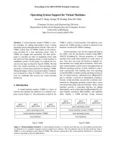
based on a client-server model. Clients implement all application functionality that is not directly involved in storage management. Thus, a client is typically an individual tool, but may be a complete environment. Software artifacts are exported from their native repository through server components called transformers. A transformer exports local objects (artifacts and relationships) as DHT nodes and links, and translates DHT messages into local operations 3
Content formatting Anchor highlighting
Source predicate eval. Resolution function eval. Anchor location
Link manipulation
Basic object ops. (get, update, create, delete) Cache management
Object Mgt.
Data serialization Low level send/receive Authentication/Encryption
Protocol i/f
DHT Node
A �xed set of operations can be applied to DHT objects: create, delete, read, and update an object. A given repository can elect to provide any subset of these operations, as appropriate for the level of access it intends to provide. In addition, any operation can be performed by a single repository on its own objects� cooperation among repositories is not required.
Presentation
Client
Cache
3 Tool Integration
GetObject("oid:LA@module:Sim%Code%sim.c")
In practice, clients are software engineering tools and environments, most of Transformer Local Access which will exist before integration by DHT. Functions It is impractical to expect users and organiRecord SELECT * FROM Modules WHERE zations to discard their favorite tools in favor Project=’Sim’ AND Form=’Code’ AND Module=’sim.c’ of new tools that understand DHT. Therefore, DHT includes a strategy for migrating existing tools to the DHT environment, and a cache mechanism to ensure that the performance of migrated tools, when accessing Figure 3: The DHT Architecture. remote nodes and links, approaches that of local object access. migration strategy speci�es four (see Figure 3). Note that from the reposi- levels The of integration: tory viewpoint, the transformer appears to be just another application. Level 0 At level 0, tools are not integrated A request-response style communicaat all. They exist unmodi�ed, and retion protocol implements the operations quire auxiliary tools to interact with speci�ed in the DHT data model (see below), DHT on their behalf. Auxiliary tools and includes provisions for locating servers simply perform node retrieval and upand authenticating and encrypting messages. date, and link resolution, to and from a The protocol also provides a form of timetool's standard input/output, or �les in stamp concurrency control �12, 16] to prevent the local �le-system. \lost updates". Level 1 Level 1 integration treats DHT Data Model. The DHT Data Model connodes as �le-like objects. Tools use �lesists of four basic objects: nodes, that repsystem calls like open(), read(), write(), resent content objects such as modules� links etc. to access a node's contents, passing that model relationships among nodes� ana string representation of the node's oid chors, that specify the points within node rather than a �le pathname. Level 1 incontents that anchor the endpoints of a link� tegration can be accomplished without and contexts, that enumerate sets of links to recompiling or modifying source code� allow speci�cation of object compositions as simply relinking the tool with a DHT sub-graphs. Nodes, links, and contexts have compatibility library (see Section 3) is types, attributes, and unique object identiall that is required. Note, however, that �ers (oids). Level 1 tools do not have access to links. Protocol i/f
4
Unix �le-system calls and converts them to DHT access operations when strings encoding DHT object identi�ers are passed as the pathname argument. The entry points are shown in Figure 4. To enable a tool for DHT access, one simply re-links it with the emulation library. Thus, the tool will continue to function as Figure 4: DHT �le-system emulation func- before when invoked with real �le names, yet tions. will retrieve contents from the DHT object cache (described below) when DHT object Level 2 At level 2, a tool is aware of links identi�ers are used. as relationships among objects, and can follow them. This awareness does not Object Caching. Many DHT objects change slowly� others see frequent access durappear at the user interface. ing a short period of time. To improve acAn example of a level 2 tool is a doc- cess latency and reduce transformer loads, it ument compiler, that resolves links of is desirable to cache frequently used objects type \Include" to incorporate text from that may be from repositories accessed over other nodes into a source node. the Internet. A cache layer is built into the the basic Level 3 At level 3, a tool integrates hypertext browsing and linking into its user- request interface to provide transparent node interface, which may require extensive and link caching. The cache is maintained modi�cation to the tool's source code. in the local �le-system� node contents are Fortunately, many tools incorporate ex- cached in separate �les to support the �letension languages or escapes to exter- io emulation library discussed above, while nal programs that can be used to im- links and node attributes are cached in a plement linking without re-compilation� hash table. Clients call a set of object acthis technique was used to implement cess functions to retrieve objects through the the DHT editor using GNU Emacs Lisp. cache layer� these are listed in Figure 5. Each DHT object has a \time-to-live" File system emulation. A vast legacy of attribute that speci�es the length of time an tools uses the �le-system as its repository. object in the cache is expected to be valid. These applications read and write objects as The cache layer uses this attribute, set by the �les through the �le-system interface, typ- transformer when the object is retrieved, to ically by calling \standard IO" �18] library invalidate objects in the cache upon access. routines supplied for the application's imple- An administrative function exists to sweep mentation language. Our goal to provide through the entire cache and remove all oba reasonable-cost implementation strategy, jects whose time-to-live has expired. precludes requiring that all of these tools be time-to-live attribute is not a guarmodi�ed to use the DHT application inter- antee The of validity, however. Certain shared face in place of the �le-system library. objects may be updated frequently by mulTo solve this problem, the DHT archi- tiple clients. To allow such clients to verify tecture exploits the �le-like nature of DHT that requested objects have not been modiatomic nodes to provide a �le-system em- �ed by another client, the cache layer can be ulation library. This library intercepts the con�gured with four cache policies to supSystem call open() access() read() write() close() stat()
Equivalent DHT operation DhtRead() same as open() read() from contents �le write() to contents �le DhtUpdate()� DhtSync() stat() on contents �le
5
Function DhtRead() DhtReadContents() DhtUpdate() DhtSync() DhtSource() DhtResolve()
Description retrieve the speci�ed objects. return the �le containing the object's contents. update the cached copy of an object. update the speci�ed object at the transformer. evaluate a link's source predicate on a node. resolve a link given a source node and anchor.
Figure 5: Cache layer interface. port speci�c application needs: 1. Never use the cached copy� always retrieve an object from the repository. 2. Use the cached copy if its time-to-live has not expired.
Local Workspace Model
3. Use the cached copy if it has not been modi�ed� verify this by retrieving the object's timestamp from the repository. 4. Always use the cached copy if present, regardless of its time-to-live or timestamp.
A B 2
edit
2
edit merge 3
merge 3 1
dht.c
1 copy
copy
Shared Workspace Model
The cache interface layer does not automatically write updates through to the repository. Instead, a separate function DhtSync() causes the cache to send an update request to synchronize the cached copy with that in the repository. This enables applications to tailor access to the cache for di�erent styles of object access. For example, by delaying synchronization and specifying the non-validation cache policy, the cache can be used as a local workspace, enabling a development style Figure 6: Software development workspace similar to that provided by NSE �1]. Ob- models. jects, once placed into the cache, are read and updated locally, and thus are not affected by updates from other developers. A \sweep" application periodically synchronizes the cached copies, possibly invoking merging tools for objects that have changed in the interim. A
edit
B
edit
dht.c
A
RCS Model
B
2
edit
3
1 check-out (lock)
6
check-out (lock)
check-in (unlock)
4
dht.c
6
check-in (unlock)
5
edit
Alternately, updates can be writtenthrough immediately, by calling DhtSync() after each update operation. This, coupled with the verifying cache policy, can be used to implement a \shared workspace" style of development (Figure 6), in which each developer sees updates from other developers upon object access. To simulate an RCS-style of development, in which developers obtain exclusive write access to an object through locking, a lock attribute must be added to objects, which is set to the user-id of the developer who seeks to lock the object. The DHT concurrency mechanism ensures that only one developer can set the lock, which is cleared when the object is \released". However, applications must cooperate by not modifying objects unless they have successfully set the lock attribute� there is no way to enforce the lock by denying updates if someone insists on updating an object. This style can be coupled with the validating or non-validating cache policy, depending on the preferences of the developer.
be performed at a given time. Monitoring allows managers and engineers to assess the current state and progress of the process. Control means ensuring the process is followed by restricting developer actions to those that conform to the process description. A process describes what steps need to be performed to develop products. At any given time, several products may be under development, so it is important for a process enactment mechanism to be able to keep track of multiple instances of a process simultaneously, and to be able to cope with the interactions among multiple processes executing concurrently. For example, a software system may have several developers performing maintenance on di�erent modules at the same time. This means that, for each module, an instance of a software maintenance process needs to be executed. Furthermore, di�erent modules developed in di�erent organizations that are part of a common system build may be constrained by di�erent software process models as well. A software process has a natural representation as a hypertext graph: the nodes represent tasks, node attributes can represent task pre- or post-condition values, while links specify the sequence in which the tasks should be performed� the resulting nodes and links can be browsed and followed just like other hypertext objects. Thus, processes can be enacted by browsing the hypertext. The links between task nodes and product nodes (artifacts) change as tasks are performed and products are created or modi�ed. In addition, the state of progress for a process instance must be maintained. Finally, enactment must take place using existing tools already familiar to users. Thus, we desire to have enactment in DHT work
4 Incorporating Process Enactment A software process is a partially ordered set of tasks that must be performed to develop software. A software process model is a description of a software process. If the description is su�ciently formalized, it is possible to execute process models for simulation, analysis, and enactment. Software process enactment uses a formal description of a software process to guide, monitor, and control the process by having a process interpreter or engine execute a formal process description. The interpreter, embedded in a software development environment, performs three functions: guidance, monitoring, and control.
Guidance involves leading developers
through the process by issuing prompts or noti�cations as to what tasks should 7
with browsers already in place, rather than introduce some new process-speci�c browser. A DHT hypertext process model contains three types of links:
support process enactment, it is necessary to keep track of this state for each process instance �9], in order to guide the developer through the process tasks in the appropriate sequence. This is the function of \availabletask" links. Available-task links serve to notify developers that a task should be performed on an artifact by linking the product to a task node. Process state is re�ected in the state of the products (artifacts) that the process instance a�ects: when the \edit" task above is performed on a module, its state changes, as re�ected by the changes to its contents and timestamp a�ected by the edit. A link source predicate can examine this state to establish a relationship between a product node and a task node. When the link's source predicate is true when applied to the product node, the link will resolve to a task node that should be performed on the product. Task nodes can either be narrative descriptions of the task to be performed, or executable scripts that perform the details of the task. In the latter case, the link's resolution function passes the node to an interpreter to execute the script. Figure 4 shows link speci�cations for the example module modi�cation process. The signi�cance of this approach to modeling process instances is that the mechanism for process enactment is embedded entirely within the process representation, as the source predicates and resolution functions of available-task links. In contrast to other enactment systems which employ an environment �13], process-aware tools �23], or process state database �9] to execute process speci�cations, DHT process models can be enacted simply by browsing the process hypertext using any DHT browser or tool. This means that process enactment can be introduced into an existing environment with minimal disruption.
1. Process decomposition links. These model the decomposition of high level tasks into lower level, smaller tasks, and eventually into primitive actions. These are static links that do not change unless the model itself is modi�ed to correct errors or re�ect changes in policy. 2. Task and action precedence links. These specify the order in which tasks should be performed. These are also static links that evolve slowly. 3. Available task links. These model the relationship between a particular product node and the tasks which should be performed on it at a given time, as speci�ed by the process model. These are dynamic links that change as the model is enacted. As an example, the following is an informal description of the process for modifying a module: 1. 2. 3. 4. 5.
Retrieve module. Edit module to implement changes. Compile module. Unit test module. if the unit test is successful, create a new version of the module� otherwise, 6. Debug the module and return to step 1. This description is a model of a process. At a given time, many instances of the process may be active, on di�erent modules by different developers. Each instance has separate process state including the module begin modi�ed, the developer doing the modi�cation, the last step completed, etc. To 8
Figure 7: Example of a process model.
Attribute source source anchor dest dest anchor type
Value {�type $node]==DHT:C}
Global
{eval �get-contents process:edit-module]}
Global DHT:Available-task
Available-task link for \edit" task. Attribute source source anchor dest dest anchor type
Value {�type $node]==DHT:C && �status $node]=="edited"}
Global
{eval �get-contents process:compile]}
Global DHT:Available-task
Available-task link for \compile" task. Attribute source source anchor dest dest anchor type
Value {�type $node]==DHT:C && �status $node]=="compiled"}
Global process:unit-test-spec Global DHT:Available-task
Available-task link for \unit-test" task. Figure 8: Available task links. 9
5 Related Work We have approached integration by providing the illusion of a central repository through the introduction of a layer between storage managers and users of data. Such a layer provides a logically integrated universe of data objects that conform to a hypertext data model. It also provides the physical integration of participating repositories necessary for users to access instances of data objects. Other research uses the same general approach we have taken, but with di�erent data models. For example, network �lesystem solutions �11, 19, 20], implement a common global �le-system at the integration layer, where each repository exports its objects as �les in a single uni�ed directory tree. However, network �le-systems are a lowest-common denominator solution �21]: the �le/directory model lacks explicit constructs to represent the numerous relationships that exist among software artifacts �17]. As a result, ad-hoc techniques such as �le naming conventions, and numerous toolspeci�c databases like Make�les, tag �les etc. are required to augment the basic directory�le model. Consequently, information sharing is at a rudimentary level. The multidatabase approach �3] occupies the other extreme: here the integration layer provides a relational or objectoriented data model with explicit relationship types. This would seem to solve the relationship problem of the network �le-system� both of these models have been used in conventional environments. However, the complexity of constructing and maintaining a single global schema that captures all of the concepts present in each participating repository, combined with the requirement that integrated repositories have database functionality, makes this approach costly and di�cult to implement �6]. A number of research projects have applied hypertext to software object manage-
ment, including the Hypertext Abstract Machine (HAM) �4], the Documents Integration Facility (DIF) �7], and HyperCASE �5]� however, these are based on a single, centralized repository architecture. Notable exceptions are PROXHY �10] and Chimera �2]. In contrast to DHT, these systems focus on adding new links among existing artifacts� existing relationships are not translated into links. Finally, ISHYS �8] and sigmaTrellis �22] explored process modeling and enactment via hypertext, although in a centralized architecture.
6 Conclusion We began with the assertion that software development in the future will be performed by cooperating development teams. These teams will be autonomous, widely distributed, and loosely associated in \virtual" enterprises, yet will need to share data in the form of software artifacts, and the relationships among them, that form the products of the development process. We observed that the conventional software environment architecture is inadequate to support virtual software enterprises, because it relies on a central repository to serve as the medium of data sharing among users� thus, we proposed to address a research problem: how do virtual enterprises share data among their dispersed, looselycoupled and autonomous participants? We proposed a solution based on providing an integration layer between autonomous software repositories and their users, that would provide the appearance of a central repository while maintaining the distributed physical environment. The integration layer achieves two levels of integration: logical integration by describing data and operations on them in terms of a common hypertext data model, and physical integration via a distributed architecture for access to
10
autonomous repositories. The DHT approach has the following bene�ts:
put in place to export data from a particular repository, the user interface and access operations to those data are also in place. Furthermore, both the user and access interface conform to a single common model, therefore maintaining highly transparent access to heterogeneous data. The result is e�ective yet low in implementation cost.
Evolutionary approach to integration
It is possible to migrate a conventional Unix toolbox oriented environment to DHT without recompiling any of the individual tools. This is because DHT o�ers several levels of tool integration, depending on the degree of \hypertext awareness" desired for a given tool. This evolutionary approach to incorporating existing tools into a DHT environment enables tool integrators to make tradeo�s between integration effort and hypertext functionality. This gives administrators great �exibility to preserve existing investment in tools and training while simultaneously obtaining the advantage of DHT's integration and hypertext capabilities
Transparent Process Enactment
By representing software processes as hypertext graphs, DHT achieves enactment without the need for an explicit process interpreter or environment. This is a signi�cant advantage in a virtual enterprise, where each participant may already have a favorite development environment in-place. The DHT approach allows process enactment to co-exist with existing tools and environments. Comprehensive solution The most signi�cant contribution of DHT is the way it applies the features of hypertext to data integration, combining intrinsic support for user interaction with data modeling and access. DHT combines the advanced data modeling capabilities of semantic nets with the natural navigation-based access of �le systems, and the intuitive direct-manipulation browsing features of hypertext. This means that as soon as a transformer is
We set out to develop a solution to the problem of sharing software engineering data among distributed, autonomous development teams, with data modeling and management appropriate for software artifacts and relationships, transparent access to heterogeneous, autonomous legacy repositories, tool integration, process modeling and enactment, and low implementation cost. DHT achieves these goals by applying hypertext concepts to logical and physical integration. In so doing, DHT solves the practical problem of sharing data in a virtual enterprise, and establishes a basis for continuing research in integrating heterogeneous software object management repositories, data models, and implementation architectures using easily navigated wide-area hypertexts. The interested reader should consult �14] for further details and examples.
References
11
�1] Evan W. Adams, Masahiro Honda, and Terrence C. Miller. Object management in a CASE environment. In Proceedings of the 11th International Conference on Software Engineering. The Association for Computing Machinery, 1989. �2] Kenneth M. Anderson, Richard N. Taylor, and E. James Whitehead, Jr,. Chimera: Hypertext for heterogeneous software environments. In European Conference on Hypermedia Technology, Edinburgh, Scotland, September 1994. �3] M. W. Bright, A. R. Hurson, and Simin H. Pakzad. A taxonomy and
�4]
�5] �6]
�7]
�8] �9]
�10]
�11]
�12]
current issues in multidatabase systems. IEEE Computer, March 1992. Brad Campbell and Joseph M. Goodman. HAM: A general purpose hypertext abstract machine. Communications of the ACM, 31(7), July 1988. Jacob L. Cybulski and Karl Reed. A hypertext based software-engineering environment. IEEE Software, March 1992. D. Fang, J. Hammer, D. McLeod, and A. Si. Remote-exchange: An approach to controlled sharing among autonomous, heterogenous database systems. In Proceedings of the IEEE Spring Compcon, San Francisco. IEEE, February 1991. Pankaj K. Garg and Walt Scacchi. A hypertext system for software life cycle documents. IEEE Software, 7(3):90{99, May 1990. Pankaj K. Garg and Walt Scacchi. On designing intelligent software hypertext systems. IEEE Expert, 1990. Dennis Heimbigner. The ProcessWall: A process state server approach to process programming. In Proceedings of the Fifth SIGSOFTSymposium on Software Development Environments, Tyson's Corner, Virginia, December 1992. Charles J. Kacmar and John J. Leggett. PROXHY: A process-oriented extensible hypertext architecture. ACM Transactions on Information Systems, 9(4):399{420, October 1991. James Kistler and Mahadev Satyanarayanan. Disconnected operation in the coda �le system. ACM Transactions on Computer Systems, 10(1):3{20, February 1992. Henry F. Korth and Abraham Silbershatz. Database System Concepts. McGraw-Hill, 1986.
�13] Pei-Wei Mi and Walt Scacchi. Process integration in CASE environments. IEEE Software, 9(2):45{54, March 1992. �14] John Noll. Software Object Management in Heterogeneous, Autonomous Environments: A Hypertext Approach. PhD thesis, University of Southern California, September 1995. �15] John Noll and Walt Scacchi. Integrating diverse information repositories: A distributed hypertext approach. IEEE Computer, 24(12):38{45, December 1991. �16] John Noll and Walt Scacchi. A hypertext system for integrating heterogeneous, autonomous software repositories. In Proceedings of the Fourth Irvine Software Symposium, pages 49{59, Irvine, CA, April 1994. Irvine Research Unit in Software and ACM/SIGSOFT. �17] Maria H. Penedo, Erhard Ploedereder, and Ian Thomas. Object management issues for software engineering environments� workshop report. In SIGSOFT '88: Proceedings of the Third ACM SIGSOFT/SIGPLAN Software Engineering Symposium on Practical Software Development Environments, Boston. The Association for Computing Machinery, 1988. �18] P. J. Plauger. The Standard C Library. Prentice Hall, 1992. �19] Herman C. Rao and Larry L. Peterson. Accessing �les in an internet: the jade �le system. IEEE Transactions on Software Engineering, 19(6):613{625, June 1993. �20] Mahadev Satyanarayanan. The in�uence of scale on distributed �le system design. IEEE Transactions on Software Engineering, 18(1):1{9, January 1992. �21] Peter Scheurmann, Clement Yu, Ahmed Elmagarmid, H~ ector Garcia-Molina,
12
Frank Manola, Dennis McLeod, A~ rnon Rosenthal, and Marjorie Templeton. Report on the workshop on heterogeneous database systems. SIGMOD Record, 19(4), December 1990. �22] P. David Stotts. sigmaTrellis: Process models as multi-reader collaborative hyperdocuments. In Proceedings of the Ninth International Software Process Workshop, Airlie, Virginia, October 1994. �23] Richard Taylor, Frank Belz, Lori Clarke, Leon Osterweil, Richard Selby, Jack Wileden, Alexander Wolf, and Mical Young. Foundations for the arcadia environment architecture. In SIGSOFT '88: Proceedings of the Third ACM SIGSOFT/SIGPLAN Software Engineering Symposium on Practical Software Development Environments, Boston. SIGSOFT/SIGPLAN, November 1988. Available in SIGSOFT Software Engineering Notes 13(5) and SIGPLAN Notices 24(2).
13