J Neurophysiol 98: 241–252, 2007. First published May 16, 2007; doi:10.1152/jn.01336.2006.
Representation of Stereoscopic Depth Based on Relative Disparity in Macaque Area V4 Kazumasa Umeda,1 Seiji Tanabe,1,2 and Ichiro Fujita2,3 1
Laboratory for Cognitive Neuroscience, Graduate School of Engineering Science and 2Laboratory for Cognitive Neuroscience, Graduate School of Frontier Biosciences, Osaka University; and 3Core Research for Evolutional Science and Technology, Japan Science and Technology Agency, Osaka, Japan Submitted 19 December 2006; accepted in final form 10 May 2007
Umeda K, Tanabe S, Fujita I. Representation of stereoscopic depth based on relative disparity in macaque area V4. J Neurophysiol 98: 241–252, 2007. First published May 16, 2007; doi:10.1152/jn.01336.2006. Stereoscopic vision is characterized by greater visual acuity when a background feature serves as a reference. When a reference is present, the perceived depth of an object is predominantly dependent on this reference. Neural representations of stereoscopic depth are expected to have a relative frame of reference. The conversion of absolute disparity encoded in area V1 to relative disparity begins in area V2, although the information encoded in this area appears to be insufficient for stereopsis. This study examines whether relative disparity is encoded in a higher cortical area. We recorded the responses of V4 neurons from macaque monkeys to various combinations of the absolute disparities of two features: the center patch and surrounding annulus of a dynamic random-dot stereogram. We analyzed the effects of the disparity of the surrounding annulus on the tuning for the disparity of the center patch; the tuning curves of relativedisparity–selective neurons for disparities of the center patch should shift with changes in the disparity of the surrounding annulus. Most V4 tuning curves exhibited significant shifts. The magnitudes of the shifts were larger than those reported for V2 neurons and smaller than that expected for an ideal relativedisparity–selective cell. No correlation was found between the shift magnitude and the degree of size suppression, suggesting that the two phenomena are not the result of a common mechanism. Our results suggest that the coding of relative disparity advances as information flows along the cortical pathway that includes areas V2 and V4. INTRODUCTION
As neural signals are conveyed along the visual pathway to higher cortical areas, visual information encoded in the retina is converted into information that directly underpins perception. The first stage of stereoscopic representation is the striate cortex (V1). Several properties of V1 neurons, however, are incompatible with perceived stereoscopic depth (Parker 2004). One excellent example is the reference frame of the encoded binocular disparity. Binocular disparity is encoded by V1 neurons in an absolute frame of reference as a result of local processing of images within the left and right eye’s receptive field, whereas depth perceived by observers largely relies on a reference in another portion of the visual field. Neural representations more directly linked to perceived depth are likely located in extrastriate areas. Address for reprint requests and other correspondence: I. Fujita, Laboratory for Cognitive Neuroscience, Graduate School of Frontier Biosciences, Osaka University, Toyonaka, Osaka 560-8531, Japan (E-mail:
[email protected]. ac.jp). www.jn.org
A vergence eye movement changes the absolute disparity of retinal images (Fig. 1A). Changes in absolute disparity are difficult to detect perceptually when a reference is not available or if the relative disparity between the absolute disparities of the target and the background remains constant (Erkelens and Collewijn 1985; Regan et al. 1986). In the presence of a background reference, the stereoacuity threshold is ten times lower (Westheimer 1979). These psychophysical findings suggest that stereoscopic depth is represented based on relative disparity in the visual system. To test the reference frame of the neural representation, it is necessary to examine neuronal responses when the two eyes are converged on a point different in depth from that of the reference. V1 neurons are selective for absolute disparity, but not for relative disparity, because disparity tuning on an absolute frame of reference dictates neuronal responses in V1 when vergence is misaligned (Cumming and Parker 1999). In area V2, responses are less affected than those in V1 by vergence misalignment from the background (Thomas et al. 2002). The majority of V2 neurons, however, are not disparity tuned in a relative frame of reference; V2 appears not to be sufficient for a complete relative-disparity representation. Area V4 receives direct axonal projections from V2 and sends its major output to the inferior temporal cortex (IT). V4 cells represent a variety of visual information such as color, orientation, spatial frequency, and even complex patterns (Desimone and Schein 1987; Desimone et al. 1985; Gallant et al. 1993; Zeki 1973). More recently, both V4 and IT were found to represent stereoscopic depth. Neurons in V4 and IT encode horizontal disparity, disparity-defined “slant” and “curvature,” or disparity of contour shapes (Hegde´ and Van Essen 2005b; Hinkle and Connor 2001, 2002; Janssen et al. 1999; Tanabe et al. 2005; Uka et al. 2000; Watanabe et al. 2002). [We use the terms “slants” and “curvatures” with quotation marks to contrast the description of three-dimensional (3-D) shapes with the description of retinal images such as orientation disparity and disparity gradient.] Many cells in V4 and IT cortex preserve their tunings to disparity-defined “slant” and “curvature” across a range of absolute pedestal disparities (Hinkle and Connor 2002; Janssen et al. 1999, 2000). Neuronal responses in V4 and IT cortex are thus not determined solely by absolute disparity. We quantitatively examined tuning curves of V4 neurons with a method similar to that described in Thomas et al. (2002) to facilitate a comparison between V4 and V2. We The costs of publication of this article were defrayed in part by the payment of page charges. The article must therefore be hereby marked “advertisement” in accordance with 18 U.S.C. Section 1734 solely to indicate this fact.
0022-3077/07 $8.00 Copyright © 2007 The American Physiological Society
241
242
K. UMEDA, S. TANABE, AND I. FUJITA
electrode micromanipulator (MO-95S, Narishige, Tokyo, Japan) were chronically implanted in each monkey. We implanted scleral search coils in both eyes to monitor eye movements (Judge et al. 1980). All animal care and experimental procedures were approved by the animal experiment committee of Osaka University and were in compliance with the National Institutes of Health Guide for the Care and Use of Laboratory Animals (1996).
Task and visual stimulus
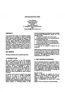
FIG. 1. Absolute-disparity– based and relative-disparity– based depth representations. A: absolute disparity reflects the depth of visual targets (open square and filled triangle) with respect to the fixation point (FP). Relative disparity is the difference in the absolute disparity between the 2 visual targets. B: top view of an observer and the stereoscopic depth in this experiment. Random-dot pattern (bottom right) illustrates the random-dot stereogram (RDS) with 2 regions: the center patch (C) and the surrounding annulus (S). C: response of a model neuron that codes for the absolute disparity of the center patch. Response is a function of 2 values: disparity of the center patch and disparity of the surrounding annulus. Discharge rate is indicated in grayscale with white areas denoting higher discharge rates. D: response of a model neuron that codes for relative disparity. Discharge rate is indicated as in C. E: tuning curves for a hypothetical absolute-disparity– coding neuron in response to the absolute disparity of feature 1 (to which the neuron is tuned) and 3 different absolute disparities of feature 2 (indicated by the solid, dotted, and dashed lines in C). F: tuning curves for a hypothetical relative-disparity– coding neuron in response to the absolute disparity of feature 1 and 3 different absolute disparities of feature 2 (indicated by the 3 lines in D).
show that compared with V2 cells, a substantial percentage of V4 neurons encode stereoscopic depth in a manner that more closely resembles an ideal relative-disparity–selective cell. The results suggest that stereo information about absolute disparities is progressively transformed into information about relative disparities along the ventral visual pathway. METHODS
We used two Japanese monkeys (Macaca fuscata), one female and one male, weighing 6 and 8 kg, respectively. The female monkey was one of the animals used in our previous studies (Tanabe et al. 2004, 2005). The general procedures are described in those papers. Briefly, a plastic head restraint and a plastic chamber for mounting an J Neurophysiol • VOL
We used programmable software (TEMPO, Reflective Computing, St. Louis, MO) to control the behavioral tasks. The monkeys were seated in a primate chair in front of a 21-in. cathode ray tube (CRT) monitor (NuVision 21MX, MacNaughton, Beaverton, OR). They were trained to fixate on a small white point at the center of the display for 2 s and were rewarded with fluid after successful trials. During the fixation, a visual stimulus was presented parafoveally for 1 s over the receptive field (RF) determined for each tested cell. We used dynamic random-dot stereograms (RDSs) to isolate stereo processing from neural processing of monocular cues. Care was taken to avoid overlap between the stimulus and the fixation point. Eye positions were measured using magnetic search coils (MEL-25, Enzansi Kogyou, Tokyo, Japan) and stored on a disk at a 1-kHz sampling rate. The electronic fixation window was typically 0.5– 0.8° from the center of the fixation point. In addition to the standard fixation window, which applies to the monocular gaze angle, we applied a binocular vergence window. The vergence angle was calculated as the horizontal position of the right eye minus the horizontal position of the left eye. The vergence window was centered at the angle where the eyes converged on the fixation point. The eyes were allowed to converge or diverge away only ⱕ0.4°. Trials were immediately aborted when the eye position crossed the borders of the window. Only data from successfully completed trials were analyzed. Visual stimuli were presented dichoptically using polarization filters that alternated the left and right eye’s image at 120 Hz (60 Hz for each eye). This dichoptic technique did not provide a perfect separation of the stereo images. Although we used only the R-gun to minimize the cross talk, we were left with a small amount of interocular cross talk. There was 10% cross talk from the left to the right eye, whereas no cross talk was detected from the right to the left eye (Tanabe et al. 2004). The asymmetry in the cross talk was a result of the asymmetrical time constants of the switches between driven and undriven states. The filter passed the left and right eye’s image in the driven and undriven states, respectively. Our stimulus was a circular patch of random dots, which consisted of bright and dark dots (3.6 and 0.5 cd/m2, respectively; 0.17 ⫻ 0.35°) on a midluminance background (2.0 cd/m2). Note that we compromised the luminance to achieve the minimal cross talk by using only one of the three CRT guns. The density of the dots was 26% and they were refreshed at 6 or 12 Hz. The RDS was bipartite with a center patch and a surrounding annulus (Fig. 1B). Binocular disparity was applied independently to each region. Hereafter, we refer to the absolute disparity of the center patch and the absolute disparity of the surrounding annulus as center disparity and surround disparity, respectively; relative disparity was defined as the center disparity minus the surround disparity. Changing the absolute disparity of the RDS center created a crescent-shaped area without dots between the center and the surrounding annulus. We filled the blank area with monocular dots. When absolute disparity was applied to the surrounding annulus, we either erased or added monocular dots on the left or right rim of the surrounding annulus. In this way, the contour of the entire patch viewed monocularly remained unchanged.
Electrophysiological recordings Custom-made glass-insulated tungsten microelectrodes (0.2–1.2 M⍀ at 1 kHz) were inserted into the prelunate gyrus. The recording chamber
98 • JULY 2007 •
www.jn.org
CODING OF RELATIVE DISPARITY IN V4
243
was centered 25 mm dorsal and 8 mm posterior to the ear canal, which allowed us to place our electrodes into V4 (Tanabe et al. 2004; Watanabe et al. 2002). We identified V4 on the basis of the relationship between the size and the eccentricity of the RF of recorded neurons as well as their locations relative to the superior temporal and lunate sulci (Desimone and Schein 1987; Gattass et al. 1988; Watanabe et al. 2002). In one of the monkeys, four pins were implanted into the brain at the corners of the recording chamber after all the experiments were completed (Fig. 2). The recording sites were then histologically confirmed to be within V4. Raw voltage signals were amplified and band-pass filtered (200 – 2,000 Hz) using custom-made instruments, and passed into a custommade window-discriminator or template-matching spike-sorting system (Multi-Spike Detector, Alpha-Omega Engineering, Nazareth, Israel). Waveforms were monitored on an oscilloscope (COR-5521, Kikusui, Yokohama, Japan). We recorded the occurrence of spikes at 1-ms resolution.
For some neurons from which we were able to record isolated spikes throughout the test for relative-disparity selectivity, we additionally performed one or more of the following tests. First, we examined the size tuning of these neurons. The RDS diameter was changed from 25 to 200% of the length of the RF diameter in steps equal to one fourth of the RF diameter. For this test, the RDS was a circular patch with zero disparity. Second, we tested the cells for relative-disparity selectivity using a wider range of surround disparities. In this test, we always included one of the surround-disparity levels used in the main test to check that the responsiveness of the neuron did not change between the two blocks of tests. Finally, we tested the cells for relative-disparity selectivity using differently sized RDSs. The size of the RDS used in this test was arbitrarily determined for each recording session, whereas the ratio of the diameter of the center patch to that of the surrounding annulus was set at 1.5. These three tests were performed in a random order.
Experimental protocol
Data analysis
The RF of each isolated V4 neuron was estimated using a small RDS patch or, in a few cases, either a bright bar or a small patch of drifting sinusoidal grating. After the RF was manually mapped, we tested each neuron for its selectivity for relative disparity. In this test, we presented an RDS over the RF with the center patch matched to the RF, except when specified otherwise. The outer diameter of the surrounding annulus was 1.5-fold the size of the diameter of the center patch. The responses of many V4 neurons are significantly attenuated by large stimuli within or beyond their RF (Desimone and Schein 1987). When recording from such cells, we reduced the center and surround size of the RDS to obtain sufficiently strong visual responses. We recorded the responses to various combinations of the center and surround disparities. In all recording sessions, the center disparity was varied between ⫺1.6 and ⫹1.6° with 0.4° steps. The tested surround disparities were ⫺0.4, 0.0, and 0.4° for most cells. Some cells from monkey 1 were tested with surround disparity levels of ⫺0.6, 0.0, and 0.6°, or ⫺0.8, 0.0, and 0.8°. Negative and positive values refer to crossed and uncrossed disparities, respectively. We also examined responses to random dots presented to only the right or left eye, and responses to RDSs that were binocularly uncorrelated for experiments in a parallel study (Tanabe et al. 2005). All of our stimulus conditions were presented in a pseudorandom order. We did not go onto the next block of trials unless all of the conditions were tested the same number of times. Neural responses to each condition were recorded in at least three independent trials (median, 10 times; mean, 9.3 times).
The neural response to the presentation of a stimulus was calculated as the mean firing rate over a 1-s period starting 80 ms after the onset of the stimulus presentation. Ongoing (spontaneous) firing rates were calculated during the 250-ms period immediately before the stimulus onset. During this period, the monkey had already fixated its gaze within the fixation window, while the RDS had not yet appeared. We summarized the neuronal responses as tuning curves. Tuning curves were constructed by plotting the mean firing rates for each condition against the absolute disparity of the center patch. If a neuron is selective for absolute disparity, it would ideally be tuned to respond to the absolute disparity of features in one plane, irrespective of the absolute disparity of features in other planes (Fig. 1, C and E). On the other hand, the response of an ideal relative-disparity–selective neuron would be constant for stimuli along an axis in which the difference between absolute disparities of the two features is constant (Fig. 1D). Thus the tuning curve for one feature on an absolute reference frame would shift in the direction and magnitude equal to the disparity shift in the other feature (Fig. 1F). To quantify the selectivity of V4 neurons for relative disparity, we analyzed the horizontal shift of their tuning curves. Disparity tuning curves were obtained for at least three different surround disparities in each tested neuron. From this data set, we estimated the shift between three pairs of tuning curves. Each pair of disparity tuning curves was fitted simultaneously with Gabor functions, given by
FIG. 2. Lateral view of the left cerebral hemisphere and the recording site in one of the monkeys used. Left and top sides indicate anterior (A) and dorsal (D) directions of the brain, respectively. Four dots indicate the position of pins inserted at the corners of the recording hole within the recording chamber. Shaded area depicts the region where the recordings were made. Recording hole covered the prelunate gyrus located between the lunate (lun) sulcus and the superior temporal (st) sulcus.
J Neurophysiol • VOL
R共x兲 ⫽ A ⫻ exp兵⫺共x ⫺ x0兲2/22其 ⫻ cos 关2ƒ共x ⫺ x0兲 ⫹ 兴 ⫹ B
where R(x) denotes the response to the center disparity x, A is the amplitude of the modulation, x0 is the horizontal offset, is the envelope width, f is the carrier frequency, is the carrier phase, and B is the baseline response. The best fit of each function was achieved by minimizing the sum-squared error between the responses of the neuron and the values of the function using the constrained minimization tool “fmincon” in the MatLab programming language (The MathWorks, Natick, MA). To tolerate data points that were clipped at a zero discharge rate, the sum-squared error was calculated from a Gabor function whose R was clipped at zero. The fit was performed with a set of constraints that limited the range of the estimated parameter values to avoid unreasonable fits (for details, see Tanabe et al. 2004). For fitting pairs of disparity tuning curves associated with two different surround disparities, three parameters (, f, and ) were shared by the two curves, whereas the other three parameters (A, B, and x0) were allowed to have independent values. The fitting of the paired Gabor functions was validated from two aspects. We first tested whether the parameters of a Gabor function were necessary for describing the disparity tuning curves in V4. The 95% confidence interval of the combination of Gabor parameters is a hyperellipsoid in a nine-dimensional space spanned by the nine
98 • JULY 2007 •
www.jn.org
244
K. UMEDA, S. TANABE, AND I. FUJITA
parameters. In nonlinear regression, individual parameters do not have a confidence interval of their own. For convenience, we calculated the projection of the hyperellipsoid onto each axis and used them as the confidence interval of each parameter as one would in linear regression. Widths of the projections are given by the diagonal elements of the covariance matrix C ⫽ (H/2)⫺1, where H is the Hessian matrix at the solution of the nonlinear regression. Of the nine parameters that were fitted, we looked at the confidence intervals of four of the positive parameters: one pair of A, , and f. If the projected 95% confidence interval of a parameter strode zero, that parameter does not have a significant contribution to the fit. This means that the fit could have been equally good even if that parameter was fixed at a value of zero. We then tested whether a Gabor function sufficiently described the disparity tuning curve. The quality of the fit was assessed by the goodness-of-fit R2 measure. This metric is the proportion of how much of the variance in the tuning data is explained by the fitted function. To statistically test whether the disparity tuning curve shifted with changes in the surround disparity, we analyzed the data using errors between the fitted tuning curves and the raw data. The null hypothesis was that the shift of a tuning curve was a result of noise variability. The null hypothesis was rejected when the residual variance of both curves fitted with independent values of x0 was statistically distinguishable from the sum-squared error of the curves fitted with a shared value of x0 in a sequential F-test with a significance level of P ⬍ 0.01 (Draper and Smith 1998). We refer to this evaluation of the shift based on the envelope offset as a position shift. We evaluated the magnitude of the observed shift as the ratio of the shift to that of an ideal relative-disparity–tuned cell. We calculated the shift ratio as Shift ratio ⫽
⌬x0 ⫺ ⌬V ⌬y ⫺ ⌬V
where x0 denotes the envelope offset, y denotes the surround disparity, and V denotes the averaged vergence angle for all of the center disparities. The ⌬ operator represents subtraction of the value associated with the smaller surround disparity (the “closer” feature) from the value associated with the larger surround disparity (the “more distant” feature). Note that the designations of smaller and larger concern the sign of the disparity. For example, the value associated with a crossed 0.4° disparity (⫺0.4°) was subtracted from the value associated with an uncrossed 0.4° disparity (⫹0.4°), but not the other way around. From the size tuning test, we assessed the suppressive influence of the stimulus size by subtracting the response to a large stimulus from the response to an optimally sized stimulus. Although this suppression is usually referred to as “surround suppression” or “surround inhibition,” we have called this effect “size suppression” herein to avoid using the word surround because “surround” might be confused with the outer region of the RDS. Size tuning curves were fitted with difference-of-error functions R共w兲 ⫽ Ae ⫻ erf
冉冊
冉 冊
w w ⫺ As ⫻ erf ⫹B ␣ ␣⫹
where R and w denote the neuronal response and the diameter of the RDS, respectively (DeAngelis and Uka 2003). The error function erf (x) is the integral of a Gaussian function over the range of ⫺⬁ to x. Ae and As denote the amplitudes of response modulation and ␣ and ␣ ⫹  represent the widths of the positive and negative error functions, respectively; B is the baseline activity. All parameters were constrained to have positive values. From the fitted size tuning curves, we calculated two measures of size suppression: the suppression strength and the suppression size index. The suppression strength is given by J Neurophysiol • VOL
Suppression strength ⫽
共Ropt ⫺ Rlargest兲 共Ropt ⫺ B兲
where Ropt and Rlargest are the values of the fitted curve at the peak and at the largest tested diameter, respectively. The suppression size index is defined as Suppression size index ⫽
wopt wRF
where wopt and wRF denote the RDS diameter at the peak of the fitted curve and the diameter of the manually mapped RF, respectively. RESULTS
We recorded from 125 V4 neurons in two monkeys performing a standard fixation task (94 from monkey 1 and 31 from monkey 2). For these neurons, we tested the selectivity for the center disparity for each group of surround disparities. Ninetyeight cells (75 from monkey 1 and 23 from monkey 2) showed significant selectivity for the disparity of the center patch combined with at least one surround disparity (Kruskal–Wallis test; P ⬍ 0.01). Eighty-three cells (65 from monkey 1 and 18 from monkey 2) were significantly selective for the center disparity combined with two or three surround disparities (Kruskal–Wallis test; P ⬍ 0.01). Shifts in the disparity tuning curves For many of the V4 neurons, the tuning curves for the center disparity shifted with changes in the surround disparity. The cell shown in Fig. 3A, for example, responded strongly to a center disparity of 0° when the surround disparity was also 0°. When the surround disparity was changed to ⫺0.4 and 0.4°, the cell responded strongly to a center disparity of ⫺0.4 and 0.4°, respectively. The maximum responses were evoked when the relative disparity of the center patch with respect to the surrounding annulus was zero. The size and direction of the shift in the tuning curves along the center disparity axis was roughly equal to the shift in the surround disparity. The shift of the peak position accompanied a decrease in the height of the peak for nonzero surround disparities. Thus this neuron primarily demonstrates selectivity for the relative disparity between the center patch and the surrounding annulus, whereas it was slightly sensitive to changes in the absolute pedestal disparity of the RDS. An alternative description of the responses of this neuron would be selectivity to the absence of a disparity edge. However, not many cells in V4 were suited for disparitycontinuity detection. For example, another cell strongly responded when the relative disparity was ⫺0.4° (Fig. 3B). The tuning curves of this neuron peaked at a relative disparity of ⫺0.4° and had a small trough at the relative disparity of ⫹0.4°. This cell represents typical responses observed in the V4 neurons, which are known to prefer small crossed disparity (as reported in Tanabe et al. 2005). The fact that only few cells responded maximally or minimally for relative disparity of zero suggests that V4 does not represent disparity-continuity or -discontinuity in the RDS. The shift in the tuning curves is evidence for relativedisparity selectivity only if the eyes’ vergence did not bring the surrounding annulus into register. If a vergence response did occur, we would see the same shift in the tuning curves even if we were to record from an absolute-disparity–selective cell.
98 • JULY 2007 •
www.jn.org
CODING OF RELATIVE DISPARITY IN V4
245
FIG. 3. Example responses of V4 neurons. A and B: tuning curves for center disparities with 3 different surround disparities from monkey 1 (M1) and monkey 2 (M2), respectively. Symbols and error bars show the means ⫾ SE of responses across 10 trials. Curves are interpolated with spline functions. Horizontal dashed line shows the mean ongoing firing rate. Bottom: time-averaged vergence angles during the response period. Vergence values represent the deviation of vergence from the ideal convergence on the fixation point.
While recording from the first example cell, the time-averaged vergence angle during the trials did not depend on the surround disparity, although it did weakly depend on the center disparity (Fig. 3A, bottom; two-way ANOVA; P values of 0.19 and 0.047, respectively). For the second example cell, the timeaveraged vergence angle depended on the surround disparity, whereas it was not dependent on the center disparity (Fig. 3B, bottom; two-way ANOVA; P ⬍ 0.0001 and P ⫽ 0.98, respectively). Although the nominal surround disparity significantly affected vergence, the magnitude of the offset was small. The average offset was ⬍3% (⫺0.01 and 0.01° for negative and positive surround disparities, respectively) of a complete registering of the surround. Thus the eyes were generally anchored well on the fixation point for the different surround disparity levels. It is unlikely that the shift in the tuning curves was caused by an absolute-disparity–selective cell in the presence of vergence alignment to the surround. Assessment of shift ratio To quantify the shift of tuning curves, we fitted Gabor functions to each pair consisting of two of the three tuning
curves. The three pairs of Gabor functions in Fig. 4 were from the three tuning curves shown in Fig. 3B. We confirmed the shifts in the Gabor fitting curves as in the spline fitting curves. In many cases including these three pairs, tuning curves shifted sideways accompanied by changes in the amplitude and baseline of the curves. Gabor functions were fitted to the tuning curve pairs (207/ 249) recorded from 83 cells. The pairs that had significant disparity selectivity for both tuning curves were subjected to the fit (Kruskal–Wallis test; P ⬍ 0.01). All four parameters had significant contributions in ⬎85% of the pairs [a pair of A: 87% (362/414), : 86% (177/207), f: 85% (176/207)]. The Gabor function did not overfit the tuning profile of V4 cells. The Gabor function adequately described the variance in the tuning data (median goodness-of-fit R2 ⫽ 0.89). Nevertheless, we discarded 42 pairs whose R2 value was ⬍0.7 for at least one tuning function, so that poorly fitted tuning functions would not confound the results. The remaining 165 pairs of curves from 75 neurons (127 pairs from 58 neurons in monkey 1 and 38 pairs from 17 neurons in monkey 2) were subjected to the analysis for evaluating the selectivity for relative disparity.
FIG. 4. Disparity tuning curves fitted with Gabor functions. A–C: 3 pairs of fitted tuning curves for the example cell in Fig. 3B. All tuning curve pairs showed shifts in the direction expected from the shift of surround disparities as indicated by the positive shift ratio inside each panel. Modulation amplitude, the baseline, and the position along the x-axis were fitted independently between the 2 curves in each pair, whereas the other parameters were constrained to share a common value.
J Neurophysiol • VOL
98 • JULY 2007 •
www.jn.org
246
K. UMEDA, S. TANABE, AND I. FUJITA
We evaluated the shift of the tuning curves by calculating the ratio of the observed shift to the shift that was expected for an ideal relative-disparity–selective cell. When calculating the shift ratio, we compensated for changes in the vergence angle (see METHODS). This compensation was necessary to estimate the absolute disparities of the retinal images because, in many recordings (e.g., Fig. 3B), the time-averaged vergence angle shifted slightly with changes in the surround disparity. The shift of vergence angle relative to the shift in the surround disparity was 4.3% (SD, 3.9) on average across 165 pairs. The shift ratios of the cell shown in Fig. 4 (same neuron in Fig. 3B) were 1.12, 0.73, and 0.89 for the three pairs of surround disparities: (⫺0.4°, 0°), (0°, ⫹0.4°), and (⫺0.4°, ⫹0.4°), respectively. For the tuning curves in Fig. 3A, the shift ratios were 0.74, 1.36, and 1.17, respectively. The tuning curves of most V4 neurons shifted in the same direction as the change in the surround disparity. For an ideal relative-disparity–selective cell, the tuning curves should shift parallel to the abscissa. The tuning curve shown in Fig. 5A displays such a shift, although the magnitude of the shift was smaller than that expected for an ideal cell (shift ratio: 0.61). Shifted tuning curves were also observed for “tuned inhibitory”-type cells (e.g., Fig. 5B). We also observed tuning curves that did not shift sideways (Fig. 5C). For one third of the tuning curve pairs (16/52 pairs for crossed and uncrossed surround disparities, 60/177 pairs for all surround disparities), the tuning curves did not show the significant shift (sequential F-test, P ⬎ 0.01). Some tuning curves demonstrated unexpected shifts. For example, the tuning curve of one neuron shifted in the direction opposite to what was expected for a relative-disparity– coding neuron (Fig. 6A). We also observed tuning curves with a calculated shift ratio that was very large, although the actual shift was not (Fig. 6B). For this cell, the tuning curve was broader than the range of tested disparities and was not properly estimated with Gabor functions. Therefore a change in the trough position without a change in the peak position would cause a large shift in the phase instead of the envelope offset; however, we forced the two curves to share the same phase parameter. The fitting algorithm resolved the shift in the trough by shifting the envelope offset. This might have caused an overestimation of the shift ratio for this pair of tuning curves.
The distribution of shift ratios in V4 To understand the overall influence of changes in the surround disparity on the tuning curves, we examined the distribution of the shift ratios for the population of V4 cells. We evaluated the distribution of shift ratios only from the pair of crossed and uncrossed surround disparities. One shift ratio thus represented data for each analyzed neuron. We selected 52 neurons that met the following two criteria: 1) significant selectivity for the center disparity in both crossed and uncrossed surround disparity conditions (Kruskal–Wallis test, P ⬍ 0.01) and 2) a reasonably good fit of the pair of tuning curves with Gabor function (R2 ⬎ 0.7). The shift ratios based on the shifts of the positions of the fitted Gabor functions were unimodally distributed and centered at a value above zero (median ⫽ 0.41, n ⫽ 52; Wilcoxon’s signed-rank test, P ⬍ 0.0001; Fig. 7A). Two thirds of the tuning curve pairs (36/52, 62%) showed shift ratios that significantly deviated from zero (sequential F-test, P ⬍ 0.01; filled columns) and almost all of the ratios (33/36) were positive. Pairs with overestimated shift ratios (such as the pair in Fig. 6B) might have biased the distribution toward positive values. To test this, we reestimated the shift ratios using an alternative method. We used spline functions to interpolate the tuning curves. Then, for a given pair of tuning curves, we simply calculated the difference in the positions of the two peaks. To calculate the shift ratio, we replaced ⌬x0 in the equation for the shift ratio with this value. This method allowed us to include 17 pairs that had been discarded based on poor fits in the previous analysis, but we had to discard four pairs that did not have a single peak in their disparity tuning curves. Distribution of the reestimated shift ratios was similar to the original distribution (median ⫽ 0.38, n ⫽ 65; Fig. 7B). The dip in the distribution was not statistically significant (Hartigan’s dip test using bootstrap resampling; P ⫽ 0.09). The two estimates of the shift ratios were not different from each other (Wilcoxon’s rank-sum test; P ⫽ 0.62) and were highly correlated on a pair-by-pair basis (Spearman’s rank correlation; r ⫽ 0.72, n ⫽ 48; P ⬍ 0.0001). The similarity between the two estimates of the shift ratios indicates that the bias for positive-shift ratios was not attributable to issues related to fitting accuracy. An ideal relative-disparity–selective cell would have a shift ratio of one, regardless of which pair of surround disparities was used. This was not the case for the population of V4 cells
FIG. 5. Examples of fitted tuning curves. A: example of a typical shift. B: a “tuned-inhibitory” neuron that showed a shift in the tuning curve. C: an example of a neuron that shifted its tuning vertically, but not horizontally.
J Neurophysiol • VOL
98 • JULY 2007 •
www.jn.org
CODING OF RELATIVE DISPARITY IN V4
247
FIG. 6. Examples of anomalous shifts. A: direction of the shift in the tuning curve of this cell was opposite to what was expected for a relative-disparity–selective cell. Opposite shift direction is represented by a negative shift ratio of ⫺1. B: this pair of tuning curves had an unusually large shift ratio.
from one of the two monkeys. For each monkey, we analyzed the shift ratio for each pair of surround disparities: crossed and uncrossed (“near”–“far”; Fig. 8, A and E), crossed and zero (“near”–“zero”; Fig. 8, B and F), and zero and uncrossed (“zero”–“far”; Fig. 8, C and G) surround disparities. In monkey 1, the distribution of the shift ratios differed significantly among the groups (Kruskal–Wallis test; P ⬍ 0.0001, n values of 41, 40, and 46; Fig. 8, A–C). The distribution of the shift ratios for “zero”–“far” pairs was strongly biased toward positive values with a median of 0.71 (Wilcoxon’s signed-rank test with Bonferroni correction; P ⬍ 0.0001; Fig. 8C). The distribution of shift ratios for “near”–“zero” pairs did not show a significant deviation from 0 (median ⫽ 0.02; P ⫽ 0.33; Fig. 8B). The shift ratios for “near”–“far” pairs showed an intermediate bias that fell between the other two groups of pairs (median ⫽ 0.40; P ⬍ 0.0005; Fig. 8A). In monkey 2, the distributions of shift ratios for all three groups were significantly biased toward positive values (Wilcoxon’s signed-rank test with Bonferroni correction; P values ⬍0.0005, ⬍0.005, and ⬍0.001, n values of 11, 15, and 12, respectively), and no
difference among the groups was observed (Kruskal–Wallis, P ⫽ 0.78; Fig. 8, E–G). The pooled histogram of all pairs showed a similar pattern of unimodal distribution centered near 0.5 for both monkeys (median values of 0.43 and 0.63, n values of 127 and 38; Fig. 8, D and H). Shift ratios were obtained for both “near”–“zero” and “zero”–“far” pairs in 45 cells. The two shift ratios were not correlated (Spearman’s rank correlation, r ⫽ ⫺0.28, P ⫽ 0.06; Fig. 8I). This shift asymmetry implies that coding of relative disparity by each V4 neuron was confined to a limited range of surround disparities. The tuning curves of many V4 neurons showed not only a horizontal shift, but also amplitude changes and vertical shifts associated with changes in the surround disparity (e.g., Figs. 4 and 5). The ratio of the amplitudes of the tuning curves for “far”–“zero” pairs (“far”/“zero”) was significantly larger than one (Fig. 9B; median ⫽ 1.13, n ⫽ 58; Wilcoxon’s signed-rank test; P ⬍ 0.0001). The ratio of amplitudes for a given pair depended on whether the pair was “near”–“zero” or “far”– “zero” (Wilcoxon’s rank-sum test; P ⬍ 0.005, n values of 55 and 58, respectively; Fig. 9, A and B), whereas the ratio of the baseline did not (P ⫽ 0.80; Fig. 9, C and D). This indicates that the only systematic relationship between the amplitude and the type of pair or between the baseline activity and the type of pair was that the tuning-curve amplitude increased when the surround disparity shifted from zero to uncrossed. Size suppression and the shift ratio
FIG. 7. Frequency distribution of the shift ratios for the tested population of V4 neurons. Shift ratios shown here were only from the pair of tuning curves with crossed and uncrossed surround disparities. A: distribution of the shift ratios obtained from the position-shift model. Filled columns denote significant shifts (sequential F-test; P ⬍ 0.01). B: distribution of the shift ratios obtained from spline curves.
J Neurophysiol • VOL
To generate neuronal selectivity for relative disparity, the information about the absolute disparity of the center disk must be integrated with that of the surround annulus. Size suppression is one of the well-known interactions between distant locations in a visual stimulus (Allman et al. 1985; Carandini 2004; Serie`s et al. 2003); visual stimuli extending beyond the classical RF often suppress the responses of neurons in V1 and other cortical areas, including V4 (Desimone and Schein 1987; Hubel and Wiesel 1968). Note that we use “size suppression” instead of “surround suppression” to avoid the confusion with the surrounding annulus of the RDS. If relative disparity is encoded by the same neural substrate underlying size suppression, one would expect a correlation between the shift ratio and a metric of size suppression. In a typical V4 cell, the discharge rate first increased, reached a maximum, and then decreased as the size of the RDS increased (Fig. 10A). We tested 49 neurons from the two monkeys for size tuning and selected 45 neurons that signifi-
98 • JULY 2007 •
www.jn.org
248
K. UMEDA, S. TANABE, AND I. FUJITA
FIG. 8. Distributions of the shift ratios grouped according to the pair of surround disparities and according to the subject from which they were recorded. A: shift ratios for “near”–“far” surround-disparity pairs from monkey 1. B: shift ratios for pairs of “near” and “zero” surround disparities. C: shift ratios for “zero”–“far” surround-disparity pairs. D: all shift ratios from monkey 1. E–H: shift ratios from monkey 2 with the same surround-disparity pairs as in A–D, respectively. Filled columns denote significant shifts (sequential F-test, P ⬍ 0.01). I: relationship of shift ratios between different combinations of surround disparity. No correlation was found between the “zero”–“far” surround disparity pair and the shift ratio from the “near”–“zero” pair (Spearman’s rank correlation, r ⫽ ⫺0.28, P ⫽ 0.06). Circles and square symbols represent the monkey identity.
cantly changed their responses according to changes in the RDS diameter (Kruskal–Wallis test; P ⬍ 0.01). We fitted the size tuning curve with a difference-of-error function and estimated the optimal size that elicited the maximal response. Most cells showed fairly good fits (median goodness-of-fit R2 ⫽ 0.95). We discarded three neurons because of poor fits (R2 ⬍ 0.7) and one neuron because no peak appeared for the range of tested diameters. For the remaining cells (n ⫽ 41), the optimal size was generally smaller than the manually mapped RF size (Fig. 10B; Wilcoxon’s signed-rank test; P ⬍ 0.0001). This indicates that size suppression begins for stimuli that are smaller than the manually determined RF, as previously reported (Desimone and Schein 1987). To quantify the suppression, we calculated two indices from the fitted curve: the suppression strength and the suppression size indices (see METHODS). Neither of the indices was correlated with the shift ratio (Fig. 10, C and D; Spearman’s rank correlation; r ⫽ 0.14, P ⫽ 0.33 and r ⫽ ⫺0.18, P ⫽ 0.23 for the suppression strength and the suppression size indices, respectively; 48 shifts from
32 cells). We found no evidence of a common mechanism underlying the shifts induced by surround disparity and size suppression.
Overlap of surround annulus with RF In our standard test for relative-disparity selectivity, the center patch was sometimes smaller than the RF and the surrounding annulus partially overlapped with the RF. To examine whether this overlap affected the magnitudes of the shifts, which was predicted by a model for relative-disparity selectivity (Thomas et al. 2002), we tested the correlation between the diameter of the center patch of the RDS relative to the diameter of the RF (the diameter ratio) and the shift ratio. The diameter ratio was not correlated with the shift ratio (Fig. 11A; Spearman’s rank correlation; r ⫽ ⫺0.09, P ⫽ 0.26, n ⫽ 158 from 72 cells). For 11 neurons, we performed the relativedisparity test with two or more differently sized RDSs. We
FIG. 9. Changes in the modulation amplitude and baseline response between pairs of surround disparities. A: histogram of amplitude ratios for “near”–“zero” surround disparities (median ⫽ 0.95). B: histogram of amplitude ratios for “far”–“zero” surround disparities (median ⫽ 1.13). C: histogram of baseline response ratios for “near”– “zero” surround disparities (median ⫽ 1.00). D: histogram of baseline response ratios for “far”–“zero” surround disparities (median ⫽ 0.97).
J Neurophysiol • VOL
98 • JULY 2007 •
www.jn.org
CODING OF RELATIVE DISPARITY IN V4
249
Structure of the response surface in a joint parameter space
FIG. 10. Relationship between size suppression and the shift ratio. A: a typical example of a size tuning curve of a V4 neuron. Symbols and error bars show the means ⫾ SE of the responses across 10 trials. B: relationship between the optimal size and the receptive field (RF) size. C: relationship between size suppression strength and the shift ratio. D: relationship between the suppression size index (optimal diameter/RF diameter) and the shift ratio.
compared the tuning curves obtained with stimuli in which the disparity edge matched the RF border with those obtained with stimuli in which the surrounding annulus substantially overlapped with the RF (Fig. 11B). The two sets of tuning curves differed only in their amplitudes and not in the characteristics of the shifts. We analyzed 14 pairs for which the shift ratio was estimated with differently sized RDSs. We found no evidence of the change in the diameter ratio affecting the shift ratio (Spearman’s rank correlation; r ⫽ 0.13, P ⫽ 0.65). It is unlikely that the overlap of the surrounding annulus with the RF caused an underestimation of the shift ratio (see DISCUSSION).
For 12 cells that were significantly selective for the center disparity with at least one surround disparity, we recorded the tuning curves using surround disparities other than the three disparities used in the standard test. To visualize these data, we color-coded the response strength and plotted them as a function of the center and surround disparities. Strong responses tended to align along an oblique axis. Some cells produced elongated diagonal areas of peak responses (Fig. 12A), as was expected for an ideal relative-disparity– coding cell shown in Fig. 1D. Other cells produced areas of peak responses in which the responsive region was diagonal at one end and bent vertically at the other end (Fig. 12B). These neurons coded for relative disparity only within a limited range of surround disparities. In a fraction of the cells, disparity-tuned responses were lost or attenuated by changes in the surround disparity. The response surface of these cells had either two responsive regions (Fig. 12C) or one responsive region (Fig. 12D). Cells responding only to certain combinations of center and surround disparities, such as those depicted in Fig. 12, C and D, imply a mechanistic explanation of relative-disparity selectivity. The existence of these combination-selective cells supports the feedforward model of relative-disparity selectivity, which is composed of combination-selective subunits (Thomas et al. 2002). DISCUSSION
In a considerable percentage of V4 cells, the tuning curve for center disparity shifts in response to changes in the surround disparity. The average magnitude of the shift for the population of V4 neurons was approximately half of that expected for ideal relative-disparity–selective cells. Therefore V4 neurons were not capable of completely coding relative disparity between the center patch and the surrounding annulus. Together with a previous study of V2 (Thomas et al. 2002), our data demonstrate a progressive conversion from an absolute-disparity– based to a relative-disparity– based representation of stereoscopic depth in the extrastriate cortex.
FIG. 11. Overlap between the annulus and the RF. A: relationship between center patch/RF diameter ratio and the shift ratio. B: example of the unchanged shifts of the disparity tuning curves despite the overlap between the annulus and the RF (solid square). Left panels: RDS overlapping the RF. Right 3 columns are the fitted disparity tuning curves for each pair of surround disparities. Top and bottom rows show similar shifts irrespective of the stimulus size.
J Neurophysiol • VOL
98 • JULY 2007 •
www.jn.org
250
K. UMEDA, S. TANABE, AND I. FUJITA
FIG. 12. Examples of the profile of response surfaces on the joint plane of center and surround disparities. A–D: center disparity is on the abscissa and surround disparity is on the ordinate. Discharge rate is represented with the color scale shown on the right of each panel.
Relative-disparity coding in V4 The distribution of the shift ratios was unimodal, unskewed, and centered at a value between zero and one. The characteristics of a typical V4 cell were between those of absolutedisparity– coding and ideal relative-disparity– coding cells. In a comparison of the distributions of the shift ratios from V4 and V2, the peak of the distribution of the V2 shift ratios was at zero (median: 0.12, Fig. 13), whereas that of the V4 shift ratios was shifted toward one (post hoc interareal comparison with Bonferroni correction; P ⬍ 0.005; median: 0.47; Fig. 13; data from Thomas et al. 2002). Additionally, the percentage of shift ratios significantly above zero was 39% (29/75) in V2, whereas the percentage was 60% (104/165) in V4, suggesting that V4 is at a more advanced stage than V2 in the progressive conversion of the representation of stereoscopic depth. The difference
FIG. 13. Direct comparison of shift ratios in 4 cortical areas. Open circles indicate the median shift ratios [⫺0.03, 0.12, 0.47, and 0.05 for areas V1, V2, V4, and middle temporal area (MT), respectively]. Error bars indicate the 25th and 75th percentiles of the distribution. Asymmetry of bar length shows that the distribution was skewed. Data are from Cumming and Parker (1999) for area V1, Thomas et al. (2002) for area V2, and Uka and DeAngelis (2006) for area MT. Data of V4 were from pooled shift ratios of all pairs of surround disparities from 2 monkeys.
J Neurophysiol • VOL
between V2 and V4 could also be a result of V2 neurons with larger shift ratios specifically projecting to V4. It remains to be determined how neurons with different shift ratios are distributed across the three types of cytochrome oxidase stripes in V2. A previously proposed model that achieves relative-disparity selectivity predicted that the shift ratio is underestimated if the surrounding annulus overlaps with the RF (Thomas et al. 2002). In other words, the observation that a cell’s shift ratio is less than one does not necessarily imply that the cell fails to encode relative disparity. We addressed this issue by examining tuning curves obtained with stimuli containing different degrees of overlap between the surrounding annulus and the RF. In contrast to the model’s prediction, the degree of overlap did not correlate with the shift ratio. Thus a typical value of a shift ratio between zero and one was unlikely to be an underestimation arising from the degree of overlap. One possible mechanism for a relative-disparity–selective cell is to sum the output of neurons that are selective for certain combinations of absolute center and surround disparities (Thomas et al. 2002). A number of V4 neurons resembled the subunits of this feedforward model (Fig. 12, C and D). The model, however, does not explain some of the observed characteristics of the V4 cells, including the observation that the shift ratio was uncorrelated with the amount of overlap between the stimulus annulus and the RF (see above). Another important contradiction is that the model predicts two groups of cells, one with a shift ratio of zero and the other with a shift ratio of one; we found only one group of cells with intermediate shift ratios between zero and one. The wiring from the combination-selective cells to a relative-disparity–selective cell may not be as precise as described by the model and other additional nonlinearities that are not included in the model may play crucial roles in the coding of relative disparities. For some V4 cells tested with additional surround disparities, a shift of the tuning curve in one direction in response to changes in the surround disparity was evident, whereas a shift in the other direction was not (e.g., Fig. 12B). With respect to
98 • JULY 2007 •
www.jn.org
CODING OF RELATIVE DISPARITY IN V4
a population, we did not find significant correlation between the shift ratio for “near”–“zero” pairs and that for “zero”–“far” pairs (Fig. 8). There was clear asymmetry of shifts in one of the two monkeys we examined (Fig. 8, B and C). With these cells, the coding of relative disparity was limited to disparity combinations whose surround disparity was uncrossed. These results suggest that relative-disparity coding in each neuron is limited to a particular range of surround disparities. Processing of stereoscopic depth along the ventral visual pathway Direct comparison of the shift ratios from areas V1, V2, and V4 shows a gradual increase along the hierarchy (median shift ratios: ⫺0.03, 0.12, and 0.47, respectively; Fig. 13; data for V1 from Cumming and Parker 1999). The shift ratio in the middle temporal area (MT) is not higher than that in V1 (median: 0.05; Fig. 13; data from Uka and DeAngelis 2006). The visual pathway including V4 gradually converts stereoscopic depth representation from an absolute to relative reference frame from the early stages. Areas along this pathway have properties that allow the encoding of 3-D object structure. Disparity-defined “slant” tuning of V4 cells and disparitygradient tuning of IT cells are similar across a range of absolute pedestal disparities (V4: Hinkle and Connor 2002; IT: Janssen et al. 1999, 2000). The response properties of these cells are tolerant to vergence misalignment, which is an expected characteristic of an ideal relative-disparity–selective cell. Hinkle and Connor (2002) reported that one third of “slant”-tuned V4 cells were tolerant to vergence misalignment; thus a number of these neurons likely code for relative disparity. However, relating this finding directly to our results is difficult because of two issues related to differences in the visual stimuli. One issue concerns the disparity continuity of the stimuli. Hinkle and Connor (2002) used a bar stimulus with a combination of orientation disparity and position disparity. The absolute disparity of any portion of the bar was a nontrivial function of the two-dimensional (2-D) position of the portion, the orientation disparity, and 2-D orientation of the bar. It is difficult to predict the responses of the presumed V1 neurons, which are selective for absolute disparity. The stimulus used in the present study consisted of patches of random dots whose absolute disparity was strictly under control. The second issue involves the difference in disparity selectivity of V4 neurons when tested with a solid-figure stereogram or an RDS. This issue is rather complicated because the disparity tuning of V4 neurons to one type of stereogram does not predict the disparity tuning to the other type of stereogram (Hegde´ and Van Essen 2005a; Tanabe et al. 2005). In V4, stereoscopic representation is not in a relative frame of reference when the disparity gradually changes in a visual stimulus (Hegde´ and Van Essen 2005b). Conversion of the reference frame is mostly complete for this kind of stimuli in IT (Janssen et al. 2000). In fact, cells are no longer driven by stimuli whose disparity is discontinuous across space. As stereoscopic processing advances along the pathway, there is a trade-off between two computations. One is the conversion of the reference frame for representing the zeroth order 3-D shape (discontinuous frontoparallel surfaces) and the other is the transformation of stereoscopic representation into higher-order 3-D shape (slanted or curved surfaces). Current data suggest J Neurophysiol • VOL
251
that no stereoscopic representation in this processing pathway achieves a complete relative frame of reference with a zeroth order 3-D shape. Comparison of stereoscopic representations in the ventral and dorsal visual pathways In contrast to V4, neurons in area MT are selective for absolute disparity. In the medial superior temporal (MST) area, some neurons have properties that imply relative-disparity selectivity (Eifuku and Wurtz 1999). Different tests, however, were used for MST cells and additional tests are required to make direct comparisons with cells from V2 (Thomas et al. 2002) and V4 (this study). Therefore current evidence suggests that the middle stages in the dorsal visual stream represent an absolute-disparity– based stereoscopic depth. This agrees with the results from imaging studies of the human brain (Neri et al. 2004). In addition, recent studies have revealed other important differences in these two pathways. Stereoscopic computation along the ventral pathway solves the stereo correspondence problem (IT: Janssen et al. 2003; V4: Tanabe et al. 2004) and the responses of IT cells are functionally linked with fine disparity discrimination (Uka et al. 2005). The representation in the ventral pathway may play a major role in perceiving detailed 3-D structures in a visual scene. In contrast, neuronal responses in MT and MST convey disparity energy signals computed in V1 (MT: Krug et al. 2004; MST: Takemura et al. 2001). Vergence eye movements are in the direction expected from the disparity energy signals conveyed along these areas (Masson et al. 1997). These mechanisms not only mediate reflexive behavior, but also underlie perceptual discrimination of coarse disparity (Uka and DeAngelis 2003, 2004, 2006). Stereoscopic depth information mediated in the middle stages of the dorsal pathway contributes to perceptual discrimination when relative disparity is irrelevent to the task, as well as to open-loop control of binocular vergence. Some reports show, in a preliminary form, that cells in the posterior parietal cortex preserve their selectivity for higherorder 3-D shape defined by disparity when pedestal disparity is varied (Stivastava et al. 2006; Taira et al. 2000), much in the same way as cells in IT (Janssen et al. 2000). How similar properties emerge in the two distant stereoscopic representations is an open question. Depth representation based on relative disparity and its reference frame If the conversion to a relative-disparity representation continues after V4, one would expect a higher shift ratio further along the processing hierarchy. As a consequence of the processing, the visual system may lose the absolute-disparity information that is present at early stages, which may appear counterproductive. Stereoscopic depth representation based only on relative disparity, however, is resistant to small translations of the retinal image caused by small eye movements, particularly vergence misalignment. Visual representations that are invariant to translations of retinal images have an object-centered reference frame. This reference frame was formalized with a theory of object recognition (Marr and Nishihara 1978) and is evident in the human brain. Visual information in some stroke patients is specifically
98 • JULY 2007 •
www.jn.org
252
K. UMEDA, S. TANABE, AND I. FUJITA
disrupted in the object-centered reference frame (for review, see Olson 2003). Information about pending saccadic eye movements is encoded in this reference frame in the supplementary eye field (Olson and Gettner 1995). Although V4 and IT cells have some translation-invariant properties (Gallant et al. 1993; Gross et al. 1972; Ito et al. 1995; Pasupathy and Connor 1999; Schwartz et al. 1983), there is no direct evidence for a representation of visual space in this reference frame. If future studies identify a complete representation of relative disparity, it would be the first demonstration of a representation of visual space in an object-centered reference frame. In summary, we examined the responses of V4 neurons to various combinations of center and surround disparities. We found significant progress toward a representation of relative disparity in V4 compared with that in V2. Therefore the visual system may use a large intercortical network to convert the reference frame of encoded visual information. ACKNOWLEDGMENTS
We thank T. Uka for comments on the manuscript and T. Doi, H. Kumano, and K. Kotani for comments and help with data collection. We are grateful to B. Cumming, O. Thomas, and A. Parker for providing data from areas V1 and V2 and to T. Uka and G. DeAngelis for data from area MT. GRANTS
This work was supported by the Ministry of Education, Culture, Sports, Science and Technology of Japan Grant 17022025 and grants from the Core Research for Evolutional Science and Technology of Japan Science and Technology Agency, the Toyota Physical and Chemical Institute, and the Takeda Science Foundation to I. Fujita. REFERENCES
Allman J, Miezin F, McGuinness E. Stimulus specific responses from beyond the classical receptive field: neurophysiological mechanisms for local-global comparisons in visual neurons. Annu Rev Neurosci 8: 407– 430, 1985. Carandini M. Receptive fields and suppressive fields in the early visual system. In: The Cognitive Neurosciences, edited by Gazzaniga MS. Cambridge, MA: MIT Press, 2004, p. 313–326. Cumming BG, Parker AJ. Binocular neurons in V1 of awake monkeys are selective for absolute, not relative, disparity. J Neurosci 19: 5602–5618, 1999. DeAngelis GC, Uka T. Coding of horizontal disparity and velocity by MT neurons in the alert macaque. J Neurophysiol 89: 1094 –1111, 2003. Desimone R, Schein SJ. Visual properties of neurons in area V4 of the macaque: sensitivity to stimulus form. J Neurophysiol 57: 835– 868, 1987. Desimone R, Schein SJ, Moran J, Ungerleider LG. Contour, color and shape analysis beyond the striate cortex. Vision Res 25: 441– 452, 1985. Draper NR, Smith HS. Applied Regression Analysis. New York: Wiley, 1998. Eifuku S, Wurtz RH. Response to motion in extrastriate area MSTl: disparity sensitivity. J Neurophysiol 82: 2462–2475, 1999. Erkelens CJ, Collewijn H. Motion perception during dichoptic viewing of moving random-dot stereograms. Vision Res 25: 583–588, 1985. Gallant JL, Braun J, Van Essen DC. Selectivity for polar, hyperbolic, and Cartesian gratings in macaque visual cortex. Science 259: 100 –103, 1993. Gattass R, Sousa APB, Gross CG. Visuotopic organization and extent of V3 and V4 of the macaque. J Neurosci 8: 1831–1845, 1988. Gross CG, Rocha-Miranda CE, Bender DB. Visual properties of neurons in inferotemporal cortex of the Macaque. J Neurophysiol 35: 96 –111, 1972. Hegde´ J, Van Essen DC. Stimulus dependence of disparity coding in primate visual area V4. J Neurophysiol 93: 620 – 626, 2005a. Hegde´ J, Van Essen DC. Role of primate visual area V4 in the processing of 3-D shape characteristics defined by disparity. J Neurophysiol 94: 2856 – 2866, 2005b. Hinkle DA, Connor CE. Disparity tuning in macaque area V4. Neuroreport 12: 365–369, 2001. Hinkle DA, Connor CE. Three-dimensional orientation tuning in macaque area V4. Nat Neurosci 5: 665– 670, 2002. Hubel DH, Wiesel TN. Receptive fields and functional architecture of monkey striate cortex. J Physiol 195: 215–243, 1968. J Neurophysiol • VOL
Ito M, Tamura H, Fujita I, Tanaka K. Size and position invariance of neuronal responses in monkey inferotemporal cortex. J Neurophysiol 73: 218 –226, 1995. Janssen P, Vogels R, Liu Y, Orban GA. At least at the level of inferior temporal cortex, the stereo correspondence problem is solved. Neuron 37: 693–701, 2003. Janssen P, Vogels R, Orban GA. Macaque inferior temporal neurons are selective for disparity-defined three-dimensional shapes. Proc Natl Acad Sci USA 96: 8217– 8222, 1999. Janssen P, Vogels R, Orban GA. Three-dimensional shape coding in inferior temporal cortex. Neuron 27: 385–397, 2000. Judge SJ, Richmond BJ, Chu FC. Implantation of magnetic search coils for measurement of eye position: an improved method. Vision Res 20: 535–538, 1980. Krug K, Cumming BG, Parker AJ. Comparing perceptual signals of single V5/MT neurons in two binocular depth tasks. J Neurophysiol 92: 1586 –1596, 2004. Marr D, Nishihara HK. Representation and recognition of the spatial organization of three-dimensional shapes. Proc R Soc Lond B Biol Sci 200: 269 –294, 1978. Masson GS, Busettini C, Miles FA. Vergence eye movements in response to binocular disparity without depth perception. Nature 389: 283–286, 1997. Neri P, Bridge H, Heeger DJ. Stereoscopic processing of absolute and relative disparity in human visual cortex. J Neurophysiol 92: 1880 –1891, 2004. Olson CR. Brain representation of object-centered space in monkeys and humans. Annu Rev Neurosci 26: 331–354, 2003. Olson CR, Gettner SN. Object-centered direction selectivity in the macaque supplementary eye field. Science 269: 985–988, 1995. Parker AJ. From binocular disparity to the perception of stereoscopic depth. In: The Visual Neurosciences, edited by Werner JS, Chalupa LM. Cambridge, MA: MIT Press, 2004, p. 779 –792. Pasupathy A, Connor CE. Responses to contour features in macaque area V4. J Neurophysiol 82: 2490 –2502, 1999. Regan D, Erkelens CJ, Collewijn H. Necessary conditions for the perception of motion in depth. Invest Ophthalmol Vis Sci 27: 584 –597, 1986. Schwartz EL, Desimone R, Albright TD, Gross CG. Shape recognition and inferior temporal neurons. Proc Natl Acad Sci USA 80: 5776 –5778, 1983. Serie`s P, Lorenceau J, Fregnac Y. The “silent” surround of V1 receptive fields: theory and experiments. J Physiol (Paris) 97: 453– 474, 2003. Srivastava S, Orban GA, Janssen P. Selectivity for three-dimensional shape in macaque posterior parietal cortex. Soc Neurosci Abstr 36: 407.9, 2006. Taira M, Tsutsui KI, Jiang M, Yara K, Sakata H. Parietal neurons represent surface orientation from the gradient of binocular disparity. J Neurophysiol 83: 3140 –3146, 2000. Takemura A, Inoue Y, Kawano K, Quaia C, Miles FA. Single-unit activity in cortical area MST associated with disparity-vergence eye movements: evidence for population coding. J Neurophysiol 85: 2245–2266, 2001. Tanabe S, Doi T, Umeda K, Fujita I. Disparity-tuning characteristics of neuronal responses to dynamic random-dot stereograms in macaque visual area V4. J Neurophysiol 94: 2683–2699, 2005. Tanabe S, Umeda K, Fujita I. Rejection of false matches for binocular correspondence in macaque visual cortical area V4. J Neurosci 24: 8170 – 8180, 2004. Thomas OM, Cumming BG, Parker AJ. A specialization for relative disparity in V2. Nat Neurosci 5: 472– 478, 2002. Uka T, DeAngelis GC. Contribution of middle temporal area to coarse depth discrimination: comparison of neuronal and psychophysical sensitivity. J Neurosci 23: 3515–3530, 2003. Uka T, DeAngelis GC. Contribution of area MT to stereoscopic depth perception: choice-related response modulations reflect task strategy. Neuron 42: 297–310, 2004. Uka T, DeAngelis GC. Linking neural representation to function in stereoscopic depth perception: roles of middle temporal area in coarse versus fine disparity discrimination. J Neurosci 26: 6791– 6802, 2006. Uka T, Tanabe S, Watanabe M, Fujita I. Neural correlates of fine depth discrimination in monkey inferior temporal cortex. J Neurosci 25: 10796 – 10802, 2005. Uka T, Tanaka H, Yoshiyama K, Kato M, Fujita I. Disparity selectivity of neurons in monkey inferior temporal cortex. J Neurophysiol 84: 120 –132, 2000. Watanabe M, Tanaka H, Uka T, Fujita I. Disparity-selective neurons in area V4 of macaque monkeys. J Neurophysiol 87: 1960 –1973, 2002. Westheimer G. Cooperative neural processes involved in stereoscopic acuity. Exp Brain Res 36: 585–597, 1979. Zeki SM. Colour coding in rhesus monkey prestriate cortex. Brain Res 53: 422– 427, 1973.
98 • JULY 2007 •
www.jn.org