Requirements for Automotive System Engineering Tools Joachim Schlosser BMW AG, EE-70 87088 Munich, Germany
[email protected]
Abstract
too, product quality as well as process quality. There are many tools on the market, but not much of them fulfil even a majority of the requirements of their own process area. Some tools have good user interfaces, but lack of the methodological background, others have good features, but are poorly implemented by simply not being able to handle the complexity of an automotive system, be it with regard of either visualization or data handling or both. This paper should try to give an impression on what kind of requirements to tools exist. As the tool chain does not exist end in itself, in the first section the general requirements to design in the automotive sector will be discussed. From the design requirements there result certain requirements to the methodology and the development process used, which will be treated in the second section. With the first two requirement areas clarified, the paper will handle the resulting requirements to the tool chain in the third section.
The requirements to system and software development tools brought up by the automotive industry differ from the requirements that other customers have. The important catchwords here are heterogeneity of suppliers, tools, technical background of the engineers, and – partially resulting from the just mentioned – the overall complexity of the systems that are built up. There are multiple suppliers delivering multiple programs and units, and all these are to be integrated into a car that has to meet a huge number of constraints regarding safety, reliability and consumer demands. This paper shows what the design of electric and electronic car systems is and has to be like, and what qualifications the methodology and the process therefore has to meet. From these two points a collection of requirements to the tools and the tool chain is derived, with a special focus on simulation tools.
2 1
Requirements to the Design of Automotive Systems
Why another Paper about Requirements? In the automotive sector, there are – in comparison to other areas where embedded computer systems are utilized – some additional aspects that result in some specific requirements.
In principle all big, complex systems have equal requirements to their design process, their methodology and so their tools. But for automotive systems it is even more complicated. Not only that the number of electronic control units (ECUs) and the amount of functionality is increasing with every new car release of any of the car manufacturers, but a big point – and a point that other industrial areas do not suffer from in the same amount – is the fact that car manufacturers are to a high degree dependent on the products of their suppliers, may it be specific products or commercialoff-the-shelf (COTS) products. Regardless whether the supplier uses the same or a different development process, the car manufacturer has the ungrateful task to integrate all the delivered functionality – packaged as an ECU in real hardware or passed as code fragments – in a car that has to meet a whole bunch of product quality, customer and security demands. Some aspects of product quality belong to the customer area, but security of course is a question of quality,
2.1
Functional Requirements
As more and more mechanical components in a car are replaced with electronic systems that realize an “increasing number of convenience and safety functions”[14], the number of functions, sensors and actuators also increases fast, and so the overall electronic system of a car becomes very complex. Sensors, e. g. for the number of wheel revolutions per minute, and actuators like brake actuators or ventilation flaps are spread across the car. It becomes clear that this huge complexity of functions cannot be integrated into a single central control unit [14], also because of the geometric constraints. Some of the sensors and actuators own some intelligence, meaning a simple unit housing a bus interface, 1
while others are connected directly to the ECU (electronic control unit) that processes or generates the data delivered or needed. Another argument against a central control unit is that certain functions need to be fault tolerant or at least fail silent, meaning that the function the system implements is either crucial for safety, or though not crucial still critical when producing wrong results. More on this can be read in section 3.3. So fault tolerance is another difference between embedded systems in the automotive sector and e. g. telecommunication. Though undesirable, an electronic system does not endanger personal lives if something fails.
2.2
is the best for one specific case or another. Obviously a separate ECU with an extra broadcast bus interface is more expensive than a dual-core CPU or a dual-CPU controller. On the other hand if there is already another ECU on the net that has enough resources to perform a replicated version of the particular function, the cost is less. Cost is a big factor, but of course then other criteria is available: What happens if the network between two ECUs fails? Generally, in order to determine which hardware components drop out at which probability, methods like FMEA (Failure Modes and Effects Analysis) [15][2] are utilized, in addition to the MTBF rates that semiconductor vendors usually provide.
2.3
Architectural Requirements
A functionality in a car like the upcoming Active Front Steering (AFS) does not exist on its own. It interacts with other functionalities like the Active Roll Stabilization by exchanging data. Furthermore the AFS does not have its own set of sensors, of course. Measurands like the individual wheel speeds, etc. are being received as messages via a broadcast bus and are shared with many other functions that require the speed signal in the same format as the AFS does. Nevertheless the complexity in the organization is not only a result of the interaction between functions, but also from the fact that many functions are implemented not by the car manufacturer but a system supplier. The supplier delivers either parts or the full function, including the hardware. As an example it may be that the car manufacturer defines a function including the interfaces. This specification is passed to the supplier who then begins to implement the function including the hardware. Mostly the operating system that runs on the hardware and possibly other functions the supplier has to integrate into the ECU are given by the car manufacturer. When the ECU is finished and tested by the supplier, the car manufacturer has the task to integrate all the ECUs from all the different vendors in an overall system and do more testing. This is usually done in several separate stages: module test, part system test, integration test and total system test. The number of suppliers and the number of functions is quite huge, and in the future a change in the process of development and a change in the fact that nearly every big function has its own ECU now will happen. The number of ECUs will be reduced, on the one hand to save money and geometric space in the car and on the other to reduce this type of complexity in order to be able to handle the upcoming complexity of increasing redundancy levels. It has to be clear that the involvement of multiple suppliers for systems and parts of systems introduces special problems. A big one is to ensure no participant’s intellectual property is disclosed. Regardless of the intellectual property, the function has to be testable and certifiable anyhow,
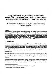
The different requirements regarding to safety lead to the realization of different bus systems, as there are not only safety critical functions that have to be deterministic and predictable in time, and so usually are configured statically [13] and run time-driven [4]. The other domain are the multimedia, information and communication functions that require a high bandwidth [11], but may have lower expectations regarding to safety. They are most often event-driven, although of course some parts may and will require nearly the same timing constraints as the safety-critical systems do. These different constraints lead to a net of sub-busses and a huge number of ECUs, as shown in figure 11 .
K-CAN System
MOST
K-CAN Peripherals
SI-Bus
Organizational and Interaction Requirements
PT-CAN
Figure 1. Current BMW 7 series bordnet structure. Boxes are ECUs. On the other hand, the functional requirement of failsilent or fault tolerant systems also implies that in order to ensure a system stays online, certain hardware components will have to be redundant, either in a symmetric or an asymmetric way. Different realizations are possible here: It is either possible to link two CPUs together directly, via an SPI [10] bus or a dual ported RAM, or to have both CPUs attached to the broadcast bus. The simple this decision appears to be, the difficult it is to determine which solution 1 Thanks to Torsten Linnemann of EE-1 dept. of BMW for the permission to use the diagram.
2
Requirements engineering
Functional simulation
ua rt Vi
Function-, system analysis
ra eg nt li
Virtual overallvehicle Test
n tio
l ua rt Vi
System design partitioning
SW analysis SW design
a gr te in
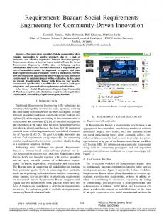
by reusing existing components. The scope of this fact is wider than it appears to be at first sight, because it implicates that there are existing models, existing source code and existing architectural structures that are to be integrated in possibly new processes and rounded out with the modified, enhanced or new functions. As a result the idealized top-down approach will be diluted with bottom-up methods, e. g. deriving structure from the items’ interfaces and interaction information. The bottom-up approach does not conflict with the V-model in every aspect, design still has to go through all the stages. Although bottom-up usually means starting with the implementation, still the requirements are gained and tests are made after implementation. The real difference lies in the compilation of the subsystems to the total system, respectively the partitioning of the total system in the design phase. In the total system set-up stage simulation may be an appropriate means for validating the design against the requirements. Most aspects are developed by analytic methods, e. g. bus load, but as theoretic thoughts always may contain errors, simulation can give additional certitude.
Vehicle test, large scale test
Acceptance trial. el. total system
n tio
Comm. test subsystem
SW integration
Implementation
Figure 2. Simplified future V-model of BMW, extended and derived from [6]
which introduces the question of who can and should be responsible for the correctness of the ECU and the compliance to all legal constraints. For various topics, there exist standards of the Association for Standardisation of Automation and Measurement Systems (ASAM) [1] in order to be able to build interoperable systems with standardized interfaces.
3
3.2
Requirements to the Methodology
The function development means the scope of the individual function rather than the whole system, here the internal structure, logic and the control circuits are designed. When talking about the integrated chassis management domain, the control circuits are usually designed using a graphical tool like Matlab/Simulink [3]. According to the requirements to the function, a model is created that reflects the behavior of the control circuits. Yet being in a early development stage, the design can be tested via simulation, including the interaction with other functions or with a model of the controlled system. Co-simulation is the keyword here; different techniques and approaches are used. In principle, the function development process consists of six phases [8]:
In the previous section some requirements that affect the design of a system were mentioned. From these needs we now will try to resolve some requirements to the process and methodology for designing automotive embedded systems. The techniques presented in this section are either already in use or in the development stage. Of course the more ideal techniques should be reviewed in this paper, as these will enable the designs of the near future.
3.1
Function Development
System Development
System development means the overall definition of functions and their general interaction, already including architectural decisions. As for nearly all other development areas the best process for designing the board net is the top-down approach. Top-down basically profits by the “divide et impera” paradigm meaning that a system does not have to be defined beginning with the detailed ECU description but the overall structure of functions and their interaction. This allows giving the total system a sensible topology and finding the optimal number of ECUs. Top-down does not exist on its own. It is tied to the lifecycle process model being used at BMW as shown in figure 2. Besides from this idealized process, in the absolute majority of cases a board net is not created from scratch. In fact the most recent existing board net will be the baseline for all development actions, to save time, work and money
1. Analysis. This initial phase the requirements to the specific function are gained and ideally modeled in an object-oriented structure via UML [5][7][12]. The requirements engineering of course includes requirements management during the whole development cycle, as there will always be iterations. 2. Specification. The specification phase the system is modeled without regarding the real world, meaning an first shot in continuous time with continuous values. Also here the environmental models are created if not already present. Functional simulation is as well done as virtual and hardware prototyping. 3. System Design. Now the real ECU architecture is considered, with the effects of limited data types and dis3
crete time. The function is allocated into a specific ECU. Ideally, virtual integration can be used to analyze timing and behavior in dependence of the hardware architecture without having it physically available.
before its possibly faulty output causes any bad effects. Failoperable (FO) in contrast is a system that can really handle one hardware error and keeps on working as if nothing has happened. With these two attributes the characteristics of a system can be described, e. g. FOFOFS is a system that can handle two hardware faults (it is fault tolerant) and goes offline if a third one occurs (and then is fail safe). Going offline can of course imply that before going offline a shutdown sequence is run to put some default values to the output ports that either put the system into a safe state or signal the fed systems that something is wrong. When finally having defined one or more possible architectures, these have to be validated. Ideally now the safety system is prototyped in software and then run on a simulator that can inject hardware errors into the virtual hardware to see if the system works as expected. This type of integration, the virtual integration, does not require real hardware to be set up, which is cost-intensive and takes a long time. If more than one architecture should be tested either sequentially or in parallel, it becomes very time-expensive. On the other hand, virtual integration requires a huge effort, too. The set-up of the architectural model and the adaptation of the software safety system are non-trivial tasks, but even then virtual integration can only supply some additional aid for the decision for an architecture. Another important task for the virtual integration is to accompany the specification and implementation process by providing the possibility to test the interface compliance and the interaction of the different ECUs. Besides the technical acceptance of course the proportional costs of the systems are calculated, which can be a criteria for technically equal designs, too.
4. Implementation. The final code is generated from models via appropriate tools. The generated code is to be compliant to the standard-core the car manufacturer uses, which generally is an OSEK [13] realization. 5. Integration and Calibration. In different sub-stages the function is built into the car system. This includes calibration of the parameters, testing with rest bus simulation and assembly with the lab car. 6. Production and after sales services. Also in this stage configuration may take place. The function, including the object code and the data, is flashed into the ECU, customized and again tested. Throughout the whole development cycle there has to be validation against the requirements and verification against the particular specification. For this ideally regression tests are used, meaning that for each requirement there is a test case that checks the correct working of the module. Automated regression testing will not be possible for all use cases and requirements due to complexity of the set-up, although this is the goal.
3.3
Architecture Design and Integration
A special attention in this paper should be put on the architecture definition process of the specification phase and the methods for virtual integration rather than physical integration. Especially in the integrated chassis management domain there is a shift towards new concepts of architecture set-up. Where there are ECUs for each functionality now, these functions will be integrated into less CPUs. This is necessary as the organization of and the interaction between the functions gets more and more complex with the future lack of mechanical fallback systems. The drive-by-wire systems so require a different interplay of functions that take influence on the individual wheels. The facts and preconditions leading to the decisions for the final architecture contain aspects like redundancy requirements, CPU load, busload and cohesion of functions. Redundancy requirements are being derived by the level of safety a system has. Derived from the FMEA information the safety class of a system can be determined by using the categories fail-silent and fail-operable. Both types of safety do not cover faulty designs but hardware errors, such as CPU outage, memory outage or data corruption, bus corruption or CPU task delay. Fail-silent (FS) means that a system recognizes an error and in consequence goes offline
4
Requirements to the Tools
The design requirements and the methodology requirements introduced in the previous two sections are realized with a set of tools that should meet certain additional requirements, too. These requirements are neither equally important nor necessarily very concrete in their substance, they may even be inconsistent in some aspects. There may be needs that interfere with others, as will be seen in the following subsections. The tool requirements will be presented in three parts General Tool Requirements, Integration with other Tools and Miscellaneous.
4.1
General Tool Requirements
Especially for modeling and simulation tools, there are some specific needs that each tool should provide. 4
Verifiability is a requirement to the design tools, too. Closely related to this is the need that they should be conformable to IEC 61508 [9], the standard defining the functional safety electronic safety-related systems. The reasons are quite obvious: If a product should be certifiable, the tools which were use to produce it have to meet the same requirements, too. This reproducibility is achieved through several prerequisites. As in other application domains, single source is preferable to multi source in the automotive domain, too. Multi source can be a consequence of different wrong techniques: A model created in one tool may have to be re-modeled in another tool because there is no link between them, which introduces the possibility of conversion mistakes and the constraint to use only one tool after the conversion. Another reason for unwanted multi source is that if an automated import from one model type into a tool is realized, but no links back to the original application. This is no problem as long as changes are only made in the original program and then re-imported into the second one. But if any design or parameter change is made in the second tool, the system gets inconsistent because it is very difficult to ensure the original model is modified the same way. When talking about models at first sight one thinks of the graphical boxes and lines that form it. In fact this is not the model itself but only its graphical representation. The information that the model contains never lies, or never should lie in the graphics. Due to the complexity mentioned in section 2.3 it is not possible to view the graphical representation of the whole model and see anything useful in it. This becomes worse when the model is not created by hand but generated through an import. Here an automation of the graphical layout is indispensable, so that the graphical representation follows certain rules that allow the developer to work with the model. The problems with the graphical representation of generated models of course is a result from the also necessary synchronization mechanisms with external sources and sinks, like mathematical model generators on the one side and simulators on the other side when having a design tool in mind. For each side there can be uni- or bi-directional synchronization. Again, this is necessary to save time for transferring the models and of course eliminate as much potential bug sources as possible. When the models are changed in external tools, the changes should be synchronizable with the tool of question, and not lead to the necessity to re-import the model from scratch and re-apply all tool specific settings. Wherever there are signals in form of tables or graphical representations like lines, a general requirement is that the developer should be able to bundle these to hide complexity. The image of this bundle should be expandably dynamically to either show or hide the details. A signal often has an
unequivocal direction, which should be visualized as well as the quality of a signal, including information like cycle time, quantity, unit and comment, or safety class. Closely related to signal bundling, handling of complexity is unthinkable without the usage of hierarchical models. This hierarchy is to be reflected in the graphics and has to be of equal method in each view of the model in the tool. A hierarchy is only useful if it is graphically expandable and can be collapsed at run-time. Besides that, tree structures are very useful that also allow the selection of different hierarchy levels that are then displayed in separate windows. These hierarchy requirements apply to all tools, whether they are responsible for functional networks or architectural networks or both. Besides that, a separation of the functional from the architectural network is very useful, because it keeps the functionality of a system independent of the hardware it is run on. Of course at a certain point in design these two models are to be merged and the glue code is to be generated that ensures the redundancy mechanisms of the hardware get used by the functions. Especially for simulation tools it is necessary that they are not only able to simulate the best case but also to inject errors and see how the designed system handles these.
4.2
Integration with other Tools
A very essential need is the seamless link to workflow accompanying tools, including configuration management (CM) and requirements management (RM). These links are absolutely necessary in order to keep the development comprehensible and reproducible, as presented in 4.1. In most cases the requirements and configuration management offers documentation generation from their databases to documents containing the accomplished milestones, changes to specifications and implementations and so are especially in the automotive domain where certifyability is very important due to the relevance of the safety systems in a machine where humans can potentially be injured. The granularity for the versioning has to be flexible, down to a certain level of model elements a part of the model should be possible to feed in the CM at once or in sub-steps. Requirements and change management is necessary to ensure a modification is made only once and with a reasonable process. An issue especially present in the automotive sector is the presence of different variants. There may be different possible functionalities in a car that overlap each other in certain parts, which does not take influence on the car because they are never built together into it. But in development, certain parts will be derived from the same models, so the tools have to support variant management of models and model primitives. Additionally, in R&D divisions of a 5
5
car manufacturer, in most cases there will be more than one car in development. So parts of a model should be usable in different projects, which brings up problems with CM and single-source that are to be solved by processes and the tools. Again, this includes variant management with the visualization of differences between similar models. When talking about import and export of models, nearly every design and simulation tool will need an interface to Matlab/Simulink [3], as this is the de-facto standard for control circuit design. On the other hand, for simulation tools it is required for them to support data formats of different model-checkers, data generation and processing tools and co-simulation back planes. The general paradigm should be that one design step is performed with only one tool to prevent from inconsistencies.
4.3
Conclusion
The car is said to be the most complex consumer product, so the process of developing these most complex consumer products require a tight development process. But a tight development process can hardly be installed without tool support. But finally, a tool shall aid a process, not define it. I would like to put special thanks in here to Dr. Peter Schiele, Dr. Michael von der Beeck and Thilo Demmeler, all BMW, for their valuable input and feedback on this paper.
References [1] Association for standardisation of automation and measuring systems homepage. http://www.asam.de. [2] FMEA Info Centre. http://www.fmeainfocentre. com. [3] The Mathworks, Inc. homepage. http://www. mathworks.com. [4] BMW AG, DaimlerChrysler AG, Robert Bosch GmbH. FlexRay Requirements Specification, 2001. [5] G. Booch, I. Jacobson, and J. Rumbaugh. Unified Modeling Language User Guide. Addison Wesley, October 1998. ISBN 0201571684. [6] Bundesamt für Wehrtechnik und Beschaffung IT I 5, Koblenz. Development Standard for IT Systems of the Federal Republic of Germany: Lifecycle Process Model, June 1997. DSK RR823320089. [7] B. P. Douglass. Real-time UML. Addison Wesley, February 1998. ISBN 0201325799. [8] S. Durach, D. Farr, and M. Geischeder. An Introduction to the EE Software Development Process. BMW AG, EE-24, Munich, April 2000. V2.2. [9] IEC 61508:1998, Functional safety of E/E/PE safety-related systems. International Electrotechnical Commission (IEC), Geneva, 1998. [10] F. G. Martin. The Mini Board Technical Reference. Media Laboratory, Massachusetts Institute of Technology, October 1995. http://fredm.www.media.mit.edu/ people/fredm/papers/mb/. [11] MOST Cooperation. MOST Specification Rev 2.1, February 2001. [12] Object Management Group. Final Report for UML 1.4.1, June 2002. http://www.omg.org/cgi-bin/doc? ad/2002-06-18. [13] OSEK/VDX Organization. OSEK/VDX Operating System Specification 2.2, September 2001. http://www. osek-vdx.org. [14] M. Peller, J. Berwanger, and R. Grießbach. Byteflight – A New High-Performance Data Bus System for Safety-Related Applications. BMW AG, EE-211 Development Safety Systems Electronics, 2000. [15] M. Villacourt. Failure Mode and Effects Analysis (FMEA): A Guide for Continuous Improvement for the Semiconductor Equipment Industry. Sematech, September 1992.
Miscellaneous
The remaining aspects describe needs that emerge from usability thoughts. They are presented unordered and again without an individual rating. The tool has to be usable offline, meaning that a developer can take his laptop into a test car and still do his work, including that changes can be fed into the system when being back in the office. To help the developer, the application has to support naming conventions by either proposing certain names or unobtrusively (without pop-ups) informing the user about violations. As for the naming conventions, consistency checks are important everywhere, to ensure a system works with itself or its neighbors. Complexity handling is a essential feature in every shadow, so the tool must be able to handle huge models and designs without overstretching the engineer by unreadable graphics. At the same time, if a database lies under the tool, it has to be multi-user capable to allow parallel development of different parts of projects. Good documentation is a must, and the same way the tool should generate documentation of the models, even specifications and test documentations. For this task the tool is to accept user-definable templates to make generated documentation e. g. compliant to the corporate identity. A good tool always has a good command line interface, with the possibility to perform most or all tasks related to transformation, simulation and generation through easy text commands. Of course, if a supplier or car manufacturer has put much effort into a model, it is unwanted that the particular counterpart can access the source information of the model, only the interfaces should be visible then. So mechanisms for preserving the confidentiality of intellectual property are to be implemented. 6