Hindawi Publishing Corporation e Scientific World Journal Volume 2014, Article ID 586403, 9 pages http://dx.doi.org/10.1155/2014/586403
Research Article Estimation of FBMC/OQAM Fading Channels Using Dual Kalman Filters Mahmoud Aldababseh and Ali Jamoos Department of Electronic Engineering, Al-Quds University, P.O. Box 20002, Jerusalem, Palestine Correspondence should be addressed to Ali Jamoos;
[email protected] Received 3 August 2013; Accepted 2 January 2014; Published 18 February 2014 Academic Editors: G. Jovanovic Dolecek and A. Materka Copyright © 2014 M. Aldababseh and A. Jamoos. This is an open access article distributed under the Creative Commons Attribution License, which permits unrestricted use, distribution, and reproduction in any medium, provided the original work is properly cited. We address the problem of estimating time-varying fading channels in filter bank multicarrier (FBMC/OQAM) wireless systems based on pilot symbols. The standard solution to this problem is the least square (LS) estimator or the minimum mean square error (MMSE) estimator with possible adaptive implementation using recursive least square (RLS) algorithm or least mean square (LMS) algorithm. However, these adaptive filters cannot well-exploit fading channel statistics. To take advantage of fading channel statistics, the time evolution of the fading channel is modeled by an autoregressive process and tracked by Kalman filter. Nevertheless, this requires the autoregressive parameters which are usually unknown. Thus, we propose to jointly estimate the FBMC/OQAM fading channels and their autoregressive parameters based on dual optimal Kalman filters. Once the fading channel coefficients at pilot symbol positions are estimated by the proposed method, the fading channel coefficients at data symbol positions are then estimated by using some interpolation methods such as linear, spline, or low-pass interpolation. The comparative simulation study we carried out with existing techniques confirms the effectiveness of the proposed method.
1. Introduction Wireless multicarrier (MC) communication systems are parallel data transmission techniques in which high data rates can be achieved by the simultaneous transmission over many orthogonal subcarriers [1]. Using MC communications, a wide-band frequency-selective fading channel is divided into many narrow-band frequency nonselective flat fading subchannels, facilitating channel estimation and equalization as well as time synchronization and narrow-band interference mitigation. In addition, the division of the whole bandwidth into many subchannels provides scalability and flexibility when configuring the communication link. The most widely used multicarrier modulation technique is orthogonal frequency division multiplexing (OFDM) with cyclic prefix (CP) [2]. Due to the various advantages of OFDM, it has become the key physical layer transmission technology adopted in current broadband communication systems such as wireless local area networks (WLAN), worldwide interoperability for microwave access (WiMAX), and long term evolution (LTE) as well as in digital video and audio
broadcasting (DVB and DAB) [2, 3]. The OFDM system offers simple implementation using the inverse fast Fourier transforms (IFFT) and the fast Fourier transform (FFT) pairs in the modulator and demodulator, respectively. However, the large side lobes of the frequency response of the filters that characterize the subcarrier channels result in significant interference among subcarriers. As an alternative to OFDM, filter bank multicarrier (FBMC) modulation, which is also implemented based on IFFT/FFT pairs, has several advantages over OFDM [4, 5]. Firstly, it does not require CP resulting in better use of the allocated spectrum. Secondly, instead of using a rectangular window, a prototype filter designed with the Nyquist pulse shaping principle is adopted, which can reduce greatly the spectral leakage problem of OFDM. This results in negligible intersymbol interference (ISI) and intercarrier interference (ICI). Thirdly, the combination of filter banks with offset quadrature amplitude modulation (FBMC/OQAM), known also as OFDM/OQAM, leads to a maximum data transmission rate [6]. Fading channel estimation and equalization techniques are crucial for coherent symbol detection at the receiver.
2 In the framework of multicarrier systems, many channel estimation techniques were proposed in the literature particularly for OFDM systems [7–11]. They can be classified as training sequence/pilot symbols based techniques and blind methods. In this paper, as blind techniques require a large amount of data and have higher complexity than training/pilot based techniques, we will focus our attention on the latter techniques. Compared to OFDM, few FBMC/OQAM studies have addressed the problem of channel estimation and equalization [12–18]. Indeed, when classical channel estimation methods used for OFDM systems are applied directly to FBMC/OQAM system, an intrinsic intersymbol-interference is observed. This results in system performance degradation. To reduce this intrinsic interference, several methods are recently proposed, including both preamble-based [12–14] and scattered pilots-based [15, 16] channel estimators. In [17], a two-stage minimum mean square error (MMSE) equalizer is proposed to cope more efficiently with intercarrier interference (ICI). A fractionally spaced adaptive decision feedback equalizer (DFE) based on the least mean square (LMS) algorithm was proposed in [18] where the input of each equalizer comprises only the output of each subcarrier. When dealing with Kalman filter based channel estimators, several approaches were developed for multicarrier systems such as multicarrier code division multiple access (MCCDMA) and OFDM [10, 11, 19]. Indeed, the Kalman filter combined with an autoregressive (AR) model to describe the time evolution of the fading channel is shown to track channel variations and to provide superior bit error rate (BER) performance over the standard LMS and recursive least square (RLS) estimators [19]. Nevertheless, the AR parameters are unknown and should be estimated. To jointly estimate the autoregressive process and its parameters from noisy observations, one of the authors of this paper has recently proposed dual Kalman filters based structure [11, 20]. This structure consists of two cross-coupled Kalman filters where the first filter uses the latest estimated AR parameters to estimate the fading process, while the second filter uses the estimated fading process to update the AR parameters. In this paper, we propose to investigate the relevance of the dual Kalman filters for the estimation of FBMC/OQAM time-varying fading channels based on pilot symbols. Once the fading channel coefficients at pilot symbol positions are estimated by the proposed method, the fading channel coefficients at data symbol positions are then to be estimated by using some interpolation methods such as linear, spline, or low-pass interpolation. The remainder of the paper is organized as follows. In Section 2, we explain the FBMC/OQAM system model. The estimation of the fading channels based on dual Kalman filters is introduced in Section 3. Simulation results are reported in Section 4. Conclusion remarks are drawn in Section 5.
2. FBMC/OQAM System Model There are different filter bank multicarrier structures that are proposed in the literature. Among them are discrete wavelet multitone [21], filtered multitone (FMT) [22], cosine modulated multitone (CMT) [23], modified discrete Fourier
The Scientific World Journal transform (MDFT) [24], exponentially modulated filter bank (EMFB) [25], and FBMC/OQAM [6]. The last is the most popular filter bank scheme that results in high bandwidth efficiency. The fundamental parts of the FBMC/OQAM system are the synthesis filter bank (SFB) at the transmitter and the analysis filter bank (AFB) at the receiver, arranged in the so-called transmultiplexer (TMUX) configuration as shown in Figures 1 and 2. It should be noted that the SFB and AFB pairs can be efficiently implemented using FFT and IFFT of size 𝑀 aided by polyphase filtering structures. When using uniformly modulated filter banks [26], a prototype filter 𝑝[𝑚] of length 𝐿 𝑝 is shifted in frequency to generate subchannels which cover the whole system bandwidth. Thus, the discrete-time baseband signal at the output of the FBMC transmitter with OQAM modulation can be expressed as 𝑀−1 ∞
𝑦 [𝑚] = ∑ ∑ 𝑥𝑘 [𝑛] 𝛽𝑘 [𝑛] 𝑝 [𝑚 − 𝑘=0 𝑛=−∞
𝑛𝑀 𝑗(2𝜋/𝑀)𝑘𝑚 ]𝑒 , (1) 2
where 𝑚 is the sample index at SFB output/AFB input, 𝑛 is the sample index at OQAM preprocessing output/postprocessing input, 𝑀 is the number of subcarriers in the filter bank, and 𝛽𝑘 [𝑛] = (−1)𝑘𝑛 exp (−𝑗
2𝜋𝑘 𝐿 𝑝 − 1 ( )) , 𝑀 2
(2)
𝑥𝑘 [𝑛] = 𝑑𝑘 [𝑛] 𝜃𝑘 [𝑛] ,
(3)
𝜃𝑘 [𝑛] = 𝑗𝑘+𝑛 .
(4)
In (3), 𝑑𝑘 [𝑛] are real-valued data symbols at subcarrier 𝑘, transmitted at a rate of 2/𝑇 where the signaling period is defined as 𝑇 = 1/Δ𝑓 with Δ𝑓 being the subcarrier spacing. The pair of symbols 𝑑𝑘 [𝑛] and 𝑑𝑘 [𝑛+1] represent, respectively, the in-phase and quadrature parts of the complex-valued input symbol 𝑐𝑘 [𝑙]. This complex-to-real conversion operation is considered to introduce an up-sampling by two. The inverse operation of real-to-complex conversion is performed at the receiver and results in down-sampling the signal by two. Thus, the complex-to-real operation performs the following mapping: Re (𝑐𝑘 [𝑙]) , 𝑑𝑘 [𝑛] = { Im (𝑐𝑘 [𝑙]) , Im (𝑐𝑘 [𝑙]) , 𝑑𝑘 [𝑛 + 1] = { Re (𝑐𝑘 [𝑙]) ,
𝑘 even 𝑘 odd 𝑘 even 𝑘 odd,
(5)
where 𝑙 is the sample index at OQAM preprocessing input/postprocessing output. Note that the complex-valued input symbols 𝑐𝑘 [𝑙] belong to QAM alphabet with the real and imaginary parts being interleaved by a time offset of 𝑇/2, resulting in OQAM modulation. To maintain orthogonality, 𝑑𝑘 [𝑛] is multiplied by 𝜃𝑘 [𝑛]. In order to achieve high spectral efficiency, complex modulated filter banks are usually used, which means that all subchannel filters are frequency shifted versions of the
The Scientific World Journal
3
𝜃0 [n] c0 [l]
Complex to real
𝛽0 [n]
d0 [n]
x0 [n]
A 0 [Z2 ]
𝜃1[n]
Complex to real
M 2
y[m]
Inverse 𝛽1[n]
c1[l]
↑
d1[n]
Z−1
fast
x1[n]
A 1 [Z2 ]
Fourier
↑
M 2
transform
. ..
𝛽M−1[n]
𝜃M−1[n]
cM−1 [l]
Complex to real
. ..
dM−1[n]
Z−1
xM−1[n]
OQAM preprocessing
A M−1 [Z2 ]
Transform block
↑
Synthesis polyphase filtering
M 2
Parallel/serial conversion
Figure 1: Block diagram of the FBMC/OQAM transmitter.
𝛽∗0 [n]
M ↓ 2
𝜃 ∗0 [n]
s 0[n] 2
B 0 [Z ]
Z−1
filtering s 1[n]
2
based
Fourier
B1[Z ]
̂ 1[n] d
̂ 1 [n] x
Real
Real to complex
transform
. . .
estimation 𝛽∗M−1 [n]
𝜃 ∗M−1 [n]
and
Z−1 M 2
̂c1[l]
channel
. ..
↓
̂c0 [l]
𝜃 ∗1 [n]
Fast
r[m]
Real to complex
Real
Kalman 𝛽∗1 [n]
M ↓ 2
̂ 0 [n] d
̂ 0 [n] x
sM−1[n]
B M−1[Z2 ]
equalization x ̂ M−1 [n]
̂ M−1[n] d
Real
Real to complex
ĉM−1[l]
OQAM postprocessing
Serial/parallel Analysis polyphase Transform block conversion filtering
Figure 2: Block diagram of the FBMC/OQAM receiver.
prototype filter 𝑝[𝑚]. So, the 𝑘th synthesis filter 𝑔𝑘 [𝑚] can be expressed as 𝑔𝑘 [𝑚] = 𝑝 [𝑚] exp (𝑗
𝐿𝑝 − 1 2𝜋𝑘 (𝑚 − )) , 𝑀 2
(6)
where 𝑚 = 0, 1, . . . , 𝐿 𝑝 − 1. The length 𝐿 𝑝 of the prototype filter 𝑝[𝑚] depends on the size of the filter bank and the number of FBMC/OQAM symbol waveforms 𝐾 that overlap in time as 𝐿 𝑝 = 𝐾𝑀.
The 𝑘th analysis filter 𝑓𝑘 [𝑚] is simply a time-reversed and complex-conjugated version of the corresponding synthesis filter: 𝑓𝑘 [𝑚] = 𝑔𝑘∗ [𝐿 𝑝 − 1 − 𝑚] .
(7)
It should be noted that the design of the prototype filter must satisfy perfect reconstruction (PR) conditions or at least provide nearly perfect reconstruction (NPR) characteristics.
4
The Scientific World Journal
However, the PR property is only achieved under the condition of ideal transmission channel. As interferences in the wireless channel are unavoidable, there is no way to have PR conditions. Thus, prototype filters are designed to satisfy NPR characteristics. In this paper, we used frequency sampling technique [27] or windowing based approach [28] to design NPR prototype filter. In these methods, the prototype filter coefficients can be obtained using a closed-form representation that includes only a few adjustable design parameters. The impulse response coefficients of the filter are obtained according to the desired frequency response, which is sampled on a 𝐾𝑀 uniformly spaced frequency point 𝜔𝑘 = 2𝜋𝑘/𝐾𝑀. So, the finite impulse response (FIR) of the low-pass prototype filter can be expressed as [29] 𝑝 [𝑚] = 𝑃 [0] 𝑈
+ 2 ∑ (−1)𝑘 𝑃 [𝑘] cos ( 𝑘=1
𝐾𝑀 − (𝐿 𝑝 − 1) 2𝜋𝑘 (𝑚 + )) , 𝐾𝑀 2 (8) 2
2
where 𝑚 = 0, 1, . . . , 𝐿 𝑝 −1, 𝑃[0] = 1, and 𝑃[𝑐] +𝑃[𝐾 − 𝑐] = 1 for 𝑐 = 1, 2, . . . , 𝐾/2, 𝑃[0] = 0 for 𝑘 = 𝐾, 𝐾 + 1, . . . , 𝑈 = (𝐾𝑀 − 2)/2. When polyphase filtering structures are used with the FFT and IFFT pairs to implement the FBMC/OQAM system, the synthesis polyphase filter at the transmitter is defined as 𝑎𝑘 [𝑚] = 𝑝 [𝑘 + 𝑚𝑀] .
(9)
At the receiver, the analysis filter polyphase is given by 𝑏𝑘 [𝑚] = 𝑎𝑀−1−𝑘 [𝑚] = 𝑝 [𝑀 − 1 − 𝑘 + 𝑚𝑀] .
(10)
The transmitted FBMC/OQAM signal 𝑦[𝑚] in (1) is assumed to go through a time-varying frequency-selective Rayleigh fading channel with background additive white Gaussian noise (AWGN). Assuming that the allocated bandwidth for each subcarrier is less than the coherence bandwidth of the wireless channel, each subcarrier undergoes frequency nonselective flat-fading. Thus, the received signal sample over the 𝑘th subcarrier for the 𝑚th FBMC/OQAM symbol can be expressed as 𝑟𝑘 [𝑚] = 𝑦𝑘 [𝑚] ℎ𝑘 [𝑚] + 𝑤𝑘 [𝑚] ,
(11)
where ℎ𝑘 [𝑚] is a complex valued fading process over the 𝑘th subcarrier for the 𝑚th FBMC/OQAM symbol and 𝑤𝑘 [𝑚] is an additive white Gaussian noise (AWGN) process. The noise processes {𝑤𝑘 [𝑚]}𝑘=0,1,...,𝑀−1 are assumed to be mutually independent and identically distributed zero-mean complex Gaussian processes, with equal variances 𝜎𝑤2 . The fading process ℎ𝑘 [𝑚] = |ℎ𝑘 [𝑚]|𝑒−𝑗𝜑𝑘 (𝑚) is assumed to be a zero-mean complex Gaussian process with uniformly distributed phase 𝜑𝑘 (𝑚) on [0, 2𝜋] and with Rayleigh distributed envelope |ℎ𝑘 [𝑚]|. The variances of the fading processes {ℎ𝑘 [𝑚]}𝑘=0,1,...,𝑀−1 are all assumed to be equal to 𝜎ℎ2 .
After processing the received signal 𝑟𝑘 [𝑚] with the analysis filter bank block, the resulting signal at the input of channel estimation and equalization is given by 𝑠𝑘 [𝑛] = [𝑟𝑘 [𝑚] ∗ 𝑓𝑘 [𝑚]]↓𝑀/2 = 𝑥𝑘 [𝑛] ⋅ 𝑞𝑘 [𝑛] + 𝜂𝑘 [𝑛] ,
(12)
where 𝑞𝑘 [𝑛] = [ℎ𝑘 [𝑚]𝑔𝑘 [𝑚] ∗ 𝑓𝑘 [𝑚]]↓𝑀/2 with ∗ denoting the convolution operator and 𝜂𝑘 [𝑛] being a Gaussian noise process with variance 𝜎𝜂2 . Under the assumption of nearly perfect reconstruction (NPR) conditions of the prototype filter, it follows that 𝑞𝑘 [𝑛] = [ℎ𝑘 [𝑚]𝑔𝑘 [𝑚] ∗ 𝑓𝑘 [𝑚]]↓𝑀/2 ≅ ℎ𝑘 [𝑛]. Thus, (12) is reduced to 𝑠𝑘 [𝑛] = 𝑥𝑘 [𝑛] ℎ𝑘 [𝑛] + 𝜂𝑘 [𝑛] ,
𝑘 = 0, 1, . . . , 𝑀 − 1. (13)
The statistical properties of the fading process ℎ𝑘 [𝑛] are given by its power spectrum density (PSD) and autocorrelation function (ACF). Indeed, the PSD of ℎ𝑘 [𝑛] is defined by the well-known U-shaped band-limited Jakes spectrum with maximum Doppler frequency 𝑓𝑑 [30]: 1 , { { 𝑆 [𝑓] = { 𝜋𝑓𝑑 √1 − (𝑓/𝑓𝑑 )2 { {0,
𝑓 ≤ 𝑓𝑑
(14)
elsewhere,
where 𝑓𝑑 = V/𝜆 with V is the mobile speed and 𝜆 is the wave length of the carrier wave. The corresponding normalized discrete-time autocorrelation function (ACF) hence satisfies 𝑅𝑘 = 𝐽0 (2𝜋𝑓𝑑 𝑇𝑠 |𝑘|) ,
(15)
where 𝐽0 (⋅) is the zero-order Bessel function of the first kind, 𝑇𝑠 is the symbol period, and 𝑓𝑑 𝑇𝑠 denotes the Doppler rate. To exploit the statistical properties of the fading channel given by its PSD and ACF, the fading process ℎ𝑘 [𝑛] can be modeled by a 𝑝th order AR process, denoted by AR(𝑝) and defined as follows [31]: 𝑝
ℎ𝑘 [𝑛] = −∑𝑎𝑖 ℎ𝑘−𝑖 [𝑛] + 𝜐𝑘 [𝑛] ,
(16)
𝑖=1
where {𝑎𝑖 }𝑖=1,2,...,𝑝 are the AR model parameters and 𝜐𝑘 [𝑛] denotes the zero-mean complex white Gaussian driving process with equal variance 𝜎𝜐2 over all subcarriers. Increasing the AR mode order 𝑝 will provide better fitting between the resulting model and the theoretical PSD and ACF [11, 31]. However, the computational complexity of the resulting channel estimation algorithm will also increase. Therefore, a compromise between the accuracy of the model and the computational complexity of the estimation algorithm has to be found. When the Doppler rate 𝑓𝑑 𝑇𝑠 is available at the receiver, the AR parameters {𝑎𝑖 }𝑖=1,2,...,𝑝 can be computed by solving the so-called Yule-Walker (YW) equations. However, as the Doppler rate 𝑓𝑑 𝑇𝑠 is usually unknown, we propose to complete the joint estimation of the fading process ℎ𝑘 [𝑛] and its AR parameters {𝑎𝑖 }𝑖=1,2,...,𝑝 based on dual Kalman filters.
The Scientific World Journal
5
Kalman filter (1) Fading process estimation
ĥ k [n]
Frequency
sk [n] xk,pilot [n]
Kalman filter (2) AR parameter estimation
Time Pilot
{̂ai }i=1, 2,..., p
Figure 4: Dual Kalman filters based structure for the joint estimation of the fading process and its AR parameters over the 𝑛th FBMC/OQAM symbol.
Data
Figure 3: Comb-type pilot arrangement.
Note that, for the sake of simplicity and clarity of presentation, the time index subscript is dropped. Then, (16) can be written in the following state-space form:
3. Dual Kalman Filters Based Channel Estimation The estimation of the fading process ℎ𝑘 [𝑛] along the 𝑛th FBMC/OQAM symbol will be performed in two steps. Firstly, the fading process ℎ𝑘 [𝑛] at the pilot symbol position is estimated using dual Kalman filters. Secondly, the fading process at data symbol position will then be estimated by using some interpolation methods such as linear, spline, or low-pass interpolation. When using comb-type pilot arrangement [8] as shown in Figure 3, 𝑁𝑝 pilots are uniformly inserted into 𝑥𝑘 [𝑛] as follows: 𝑥𝑘 [𝑛] = 𝑥𝑢𝐿+𝑖 [𝑛] {𝑥𝑢𝐿,pilot [𝑛] , ={ {𝑥𝑢𝐿+𝑖,data [𝑛] ,
h𝑘 = 𝜙h𝑘−1 + g𝜐𝑘 ,
(19)
where −𝑎1 −𝑎2 ⋅ ⋅ ⋅ −𝑎𝑝 1 0 ⋅⋅⋅ 0 ] ] .. .. ] , .. . . d . ] [ 0 ⋅⋅⋅ 1 0 ]
[ [ 𝜙=[ [
(20)
𝑇
g = [1 0 ⋅ ⋅ ⋅ 0] . In addition, given (13) and (18), it follows that
𝑖=0
(17)
where 𝑥𝑢𝐿,pilot [𝑛] is the 𝑢th pilot symbol with 𝑢 = 0, 1, . . . , 𝑁𝑝 − 1, and 𝐿 = 𝑀/𝑁𝑝 is the pilot interval spacing with 𝑀 being the number of subcarriers. Thus, using known comb-type pilot symbols 𝑥𝑘 [𝑛] = 𝑥𝑘,pilot [𝑛], we propose to jointly estimate the fading process ℎ𝑘 [𝑛] and its AR parameters {𝑎𝑖 }𝑖=1,2,...,𝑝 based on dual Kalman filters as shown in Figure 4. Indeed, the first Kalman filter in Figure 4 uses the pilot symbol 𝑥𝑘,pilot [𝑛], the output of the analysis filter bank 𝑠𝑘 [𝑛], and the latest estimated AR parameters {̂ 𝑎𝑖 }𝑖=1,2,...,𝑝 to estimate the fading process ℎ𝑘 [𝑛], while the second Kalman filter uses the estimated fading process ̂ℎ [𝑛] to update the AR parameters. 𝑘 3.1. Fading Process Estimation at Pilot Symbol Positions. In this subsection, our purpose is to estimate the fading process ℎ𝑘 [𝑛] over the 𝑛th FBMC/OQAM symbol based on Kalman filtering with known pilot symbols. To this end, let us define the state vector as follows: 𝑇
(21)
𝑇
𝑖 = 1, 2 . . . , 𝐿 − 1,
h𝑘 = [ℎ𝑘 ℎ𝑘−1 ⋅ ⋅ ⋅ ℎ𝑘−𝑝+1 ] .
𝑠𝑘 = x𝑘𝑇 h𝑘 + 𝜂𝑘 ,
(18)
where x𝑘 = [𝑥𝑘,pilot 0 ⋅ ⋅ ⋅ 0] . Hence, (19) and (21) represent the state-space model dedicated to the 𝑛th FBMC/OQAM symbol fading channel system (13) and (16). A standard Kalman filtering algorithm ̂ can then be carried out to provide the estimation h 𝑘/𝑘 of the state vector h𝑘 given the set of observations {𝑠𝑖 }𝑖=1,...,𝑘 . To this end, let us introduce the so-called innovation process 𝛼𝑘 which can be obtained as follows: ̂ 𝛼𝑘 = 𝑠𝑘 − x𝑘𝑇 𝜙h 𝑘−1/𝑘−1 .
(22)
The variance of the innovation process can be expressed as 𝐶𝑘 = 𝐸 [𝛼𝑘 𝛼𝑘∗ ] = x𝑘𝑇 P𝑘/𝑘−1 x𝑘 + 𝜎𝜂2𝑘 ,
(23)
where the so-called a priori error covariance matrix P𝑘/𝑘−1 can be recursively obtained as follows: P𝑘/𝑘−1 = 𝜙P𝑘/𝑘−1 𝜙𝐻 + g𝜎𝜐2 g𝑇 .
(24)
The Kalman gain is calculated in the following manner: K𝑘 = P𝑘/𝑘−1 x𝑘 𝐶𝑘−1 .
(25)
6
The Scientific World Journal
The a posteriori estimate of the state vector and the fading process are, respectively, given by
Taking into account that P𝑘/𝑘−1 is a symmetric Hermitian matrix, one can rewrite (25) in the following manner:
̂ ̂ = 𝜙h h 𝑘/𝑘 𝑘−1/𝑘−1 + K𝑘 𝛼𝑘 ,
b𝑇𝑘 P𝑘/𝑘−1 = 𝐶𝑘 K𝐻 𝑘 ,
̂ℎ = ̂ℎ = g𝑇h ̂ . 𝑘 𝑘/𝑘 𝑘/𝑘
(26)
By combining (33) and (34), 𝜎𝜐2 can be expressed as follows:
The error covariance matrix is updated as follows: P𝑘/𝑘 = P𝑘/𝑘−1 −
K𝑘 x𝑘𝑇 P𝑘/𝑘−1 .
(27)
3.2. Estimation of the AR Parameters. To estimate the AR parameters from the estimated fading process ̂ℎ𝑘 , (26) are firstly combined such as the estimated fading process is a function of the AR parameters:
̂ where h 𝑘−1
=
𝑇
[̂ℎ𝑘−1 ̂ℎ𝑘−2 ⋅ ⋅ ⋅ ̂ℎ𝑘−𝑝 ] and a𝑘
(28) =
[−𝑎1 −𝑎2 ⋅ ⋅ ⋅ −𝑎𝑝 ] . In addition, the variance of the process 𝜍𝑘 = g𝑇K𝑘 𝛼𝑘 is given by 𝜎𝜍2𝑘 = g𝑇 K𝑘 𝐶𝑘 KH 𝑘 g.
(29)
When the channel is assumed stationary, the AR parameters are invariant and satisfy the following relationship: a𝑘 = a𝑘−1 .
(30)
As (28) and (30) define a state-space representation for the estimation of the AR parameters, a second Kalman filter can be used to recursively estimate a𝑘 as follows: 𝑇 ̂a𝑘 = ̂a𝑘−1 + Ka𝑘 (̂ℎ𝑘 − ̂ℎ𝑘−1 ̂a𝑘−1 ) ,
(31)
where the Kalman gain Ka𝑘 and the update of the error covariance matrix Pa are, respectively, given by 2 −1 ̂𝐻 P h ̂ ∗ (h ̂ Ka𝑘 = Pa𝑘−1 h 𝑘−1 𝑘−1 a𝑘−1 𝑘−1 + 𝜎𝜍𝑘 ) ,
̂𝑇 P Pa𝑘 = Pa𝑘−1 − Ka𝑘 h 𝑘−1 a𝑘−1
(35)
where f = [g𝑇g] g𝑇 = g𝑇 is the pseudoinverse of g. Thus, we propose to estimate 𝜎𝜐2 recursively as follows: 𝜎̂𝜐2𝑘 = 𝜆𝜎𝜐2𝑘−1 + [1 − 𝜆] 2 𝑇 × f [P𝑘/𝑘 − 𝜙P𝑘−1/𝑘−1 𝜙𝐻 + K𝑘 𝛼𝑘 K𝐻 𝑘 ]f ,
(36)
where the variance of the innovation process 𝐶𝑘 is replaced by its instantaneous value |𝛼𝑘 |2 and 𝜆 is the forgetting factor. It should be noted that 𝜆 can be either constant or time-varying (e.g., 𝜆 𝑘 = (𝑘 − 1)/𝑘). 3.4. Fading Process Estimation at Data Symbol Positions. Once the fading process at pilot symbol positions is estimated by the dual Kalman filters, the fading process at data symbol positions will then be estimated by using some interpolation methods such as linear, spline, or low-pass interpolation [8]. (1) Linear Interpolation. Using linear interpolation method, the channel estimates at data positions, 𝑢𝐿 < 𝑘 < (𝑢 + 1)𝐿, are given by 𝑙 ̂ ̂ ̂ℎ = (̂ℎ + ℎ𝑝𝑘 , 𝑘 𝑝𝑘+1 − ℎ𝑝𝑘 ) 𝐿
0 ≤ 𝑙 < 𝐿,
(37)
where ̂ℎ𝑝𝑘 is the estimated fading process at pilot symbol position. (2) Low-Pass Interpolation. The low-pass interpolation is carried out by inserting zeros into the data symbol positions of the original sequence and then applying a special low-pass filter. In this paper, we use the Matlab function interp. (3) Spline Interpolation. Spline interpolation produces a smooth and continuous polynomial fitted to the estimated fading process at pilot symbol positions. In this paper, we use the Matlab function spline.
(32)
with initial conditions ̂a0 = 0 and Pa0 = I𝑝 . 3.3. Estimation of the Driving Process Variance. To estimate the driving process variance 𝜎𝜐2 , the Riccati equation is first obtained by inserting (24) in (27) as follows: P𝑘/𝑘 = 𝜙P𝑘−1/𝑘−1 𝜙𝐻 + g𝜎𝜐2𝑘 g𝑇 − K𝑘 x𝑘𝑇 P𝑘/𝑘−1 .
𝑇 𝜎𝜐2 = f [P𝑘/𝑘 − 𝜙P𝑘−1/𝑘−1 𝜙𝐻 + K𝑘 𝐶𝑘 K𝐻 𝑘 ]f , −1
It should be noted that the state vector and the error covariance matrix are initially assigned to zero vector and ̂ = 0 and P = I . identity matrix, respectively; that is, h 0/0 0/0 𝑝 Equations (22)–(27) can be evaluated providing the availability of the AR parameters that are involved in the transition matrix 𝜙 and the driving process variance 𝜎𝜐2 . They will be estimated in the next subsections.
̂ + g𝑇 K 𝛼 = h ̂𝑇 a + 𝜍 , ̂ = g𝑇𝜙h h 𝑘 𝑘−1 𝑘 𝑘 𝑘 𝑘−1 𝑘
(34)
(33)
3.5. Fading Channel Equalization. Once the fading process at pilot and data symbols is estimated using the proposed approach, channel equalization can be performed by multiplying (13) with a normalized version of the complex conjugate of the channel estimate as follows: ̂ℎ∗ [𝑛] 𝑥̂𝑘 [𝑛] = 𝑠𝑘 [𝑛] ( 𝑘 2 ) . ̂ℎ [𝑛] 𝑘
(38)
The Scientific World Journal
7 100
10 5
Bit error rate (BER)
Envelope (dB)
0 −5 −10
10−1
10−2
−15 −20 −25 100
10−3
110
120
130
140
150 160 Symbols
170
180
190
200
0
6 8 10 12 14 16 Signal-to-noise ratio (SNR) (dB)
18
20
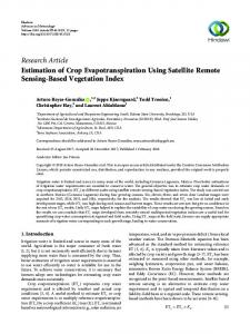
Figure 6: BER performance versus SNR for the FBMC/OQAM system with the various channel estimators. 𝑀 = 2048, 𝑁𝑝 = 1024, and 𝑓𝑑 𝑇𝑠 = 0.0167.
4. Simulation Results
100
Bit error rate (BER)
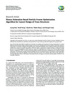
In this section, we carry out a comparative simulation study on the estimation of FBMC/OQAM fading channels between the proposed dual Kalman filters based channel estimator and the conventional LMS and RLS channel estimators. In addition, we test the performance of three interpolation techniques, namely, low-pass, spline, and linear interpolation. Furthermore, we investigate the effect of the number of pilot symbols 𝑁𝑝 and Doppler rate 𝑓𝑑 𝑇𝑠 on the BER performance. In all of our simulations, the fading channels are generated according to the autoregressive based method presented in [31]. The autoregressive model order 𝑝 in the proposed dual Kalman filters based estimator is set to 𝑝 = 2. The step size for LMS algorithm is set to 𝜇 = 0.5 and the forgetting factor for RLS algorithm is set to 𝜆 = 0.1. Figure 5 shows the envelope of estimated fading process using the various channel estimators with low-pass interpolation, SNR = 15 dB, 𝑀 = 2048, 𝑁𝑝 = 1024, and𝑓𝑑 𝑇𝑠 = 0.0167. One can notice that the dual Kalman filters based estimator provides much better estimation than the LMS and RLS based ones. Figure 6 shows the BER performance versus SNR for the FBMC/OQAM system when using the various channel estimators with 𝑀 = 2048, 𝑁𝑝 = 1024 pilots, 𝑓𝑑 𝑇𝑠 = 0.0167, and using low-pass interpolation. According to Figure 6, the proposed dual Kalman filters based estimator outperforms the conventional LMS and RLS estimators with the performance difference increasing as the SNR increases. Figure 7 displays the BER performance of the FBMC/OQAM system versus Doppler rate when using the various channel estimators with low-pass interpolation, 𝑀 = 2048, and 𝑁𝑝 = 1024 pilots. One can notice that the dual Kalman filters
4
Known channel LMS estimation RLS estimation Dual Kalman filters estimation
Known channel envelope Dual Kalman filters estimation RLS estimation LMS estimation
Figure 5: Envelope of estimated fading process using the various estimators. SNR = 15 dB, 𝑀 = 2048, 𝑁𝑝 = 1024, and 𝑓𝑑 𝑇𝑠 = 0.0167.
2
10−1
10−2
10−3 0.01
0.02
0.03
0.04 0.05 0.06 0.07 Doppler rate fd Ts
0.08
0.09
0.1
Known channel LMS estimation RLS estimation Dual Kalman filters estimation
Figure 7: BER performance versus Doppler rate for the FBMC/OQAM system with the various channel estimators. SNR = 15 dB, 𝑀 = 2048, and 𝑁𝑝 = 1024.
based estimator yields lower BER performance than the LMS and RLS estimators with the BER performance difference increasing as the Doppler rate increases. This confirms that the dual Kalman filters based estimator can exploit the fading channel statistics and can track fast variations of rapidly varying fading channels.
8
The Scientific World Journal Figure 9 shows the BER performance of the FBMC/ OQAM system when using dual Kalman filters with the various interpolation methods, 𝑀 = 2048, 𝑁𝑝 = 256 pilots, and 𝑓𝑑 𝑇𝑠 = 0.0167. It is confirmed that the low-pass interpolation yields the best BER performance.
Bit error rate (BER)
100
10−1
5. Conclusions 10
−2
10−3
0
2
4
6
8
10
12
14
16
18
20
Signal-to-noise ratio (SNR) (dB) 1024 pilots 512 pilots 256 pilots
128 pilots 64 pilots
Figure 8: BER performance versus SNR for the FBMC/OQAM system with different number of pilot symbols. 𝑀 = 2048 and 𝑓𝑑 𝑇𝑠 = 0.0167.
Bit error rate (BER)
Conflict of Interests The authors declare that they have no conflict of interests regarding the publication of this paper.
References
100
10−1
10−2
This paper addresses the estimation and equalization of FBMC/OQAM fading channels based on pilot symbols. A dual Kalman filters based structure is proposed for the joint estimation of the fading process and its AR parameters over each subcarrier at pilot symbol positions. The fading process at data symbol positions is then obtained by using some interpolation methods such as linear, spline, or low-pass interpolation. The simulation results showed that the proposed dual Kalman filters based estimator outperforms the LMS and RLS based ones. In addition, the low-pass interpolation is confirmed to outperform both spline and linear interpolation.
0
2
4
6 8 10 12 14 16 Signal-to-noise ratio (SNR) (dB)
18
20
Low-pass interpolation Spline interpolation Linear interpolation
Figure 9: BER performance versus SNR for the FBMC/OQAM system with the various interpolation methods. 𝑀 = 2048, 𝑁𝑝 = 256, and 𝑓𝑑 𝑇𝑠 = 0.0167.
The effect of changing the number of pilot symbols 𝑁𝑝 on the BER performance of the FBMC/OQAM system when using dual Kalman filters based channel estimator with lowpass interpolation is shown in Figure 8. Indeed, increasing the number of pilot symbols 𝑁𝑝 will improve the BER performance of the system.
[1] Z. Wang and G. B. Giannakis, “Wireless multicarrier communications: where Fourier meets Shannon,” IEEE Signal Processing Magazine, vol. 17, no. 3, pp. 29–48, 2000. [2] G. Li and G. Stuber, Orthogonal Frequency Division Multiplexing for Wireless Communications, Springer, New York, NY, USA, 2006. [3] K. Baum, B. Classon, and P. Sartori, Principles of Broadband OFDM Cellular System Design, Wiley-Blackwell, New York, NY, USA, 2009. [4] B. Farhang-Boroujeny, “OFDM versus filter bank multicarrier,” IEEE Signal Processing Magazine, vol. 28, no. 3, pp. 92–112, 2011. [5] H. Zhang, D. Le Ruyet, D. Roviras, Y. Medjahdi, and H. Sun, “Spectral efficiency comparison of OFDM/FBMC for uplink cognitive radio networks,” Eurasip Journal on Advances in Signal Processing, vol. 2010, Article ID 621808, 2010. [6] P. Siohan, C. Siclet, and N. Lacaille, “Analysis and design of OFDM/OQAM systems based on filterbank theory,” IEEE Transactions on Signal Processing, vol. 50, no. 5, pp. 1170–1183, 2002. [7] M. K. Ozdemir and H. Arslan, “Channel estimation for wireless OFDM systems,” IEEE Communications Surveys & Tutorials, vol. 9, no. 2, pp. 18–48, 2007. [8] S. Coleri, M. Ergen, A. Puri, and A. Bahai, “Channel estimation techniques based on pilot arrangement in OFDM systems,” IEEE Transactions on Broadcasting, vol. 48, no. 3, pp. 223–229, 2002. [9] J. H. Manton, “Optimal training sequences and pilot tones for OFDM systems,” IEEE Communications Letters, vol. 5, no. 4, pp. 151–153, 2001. [10] W. Chen and R. Zhang, “Estimation of time and frequency selective channels in OFDM systems: a Kalman filter structure,” in Proceedings of the IEEE Global Telecommunications Conference (GLOBECOM ’04), pp. 800–803, December 2004.
The Scientific World Journal [11] A. Jamoos, A. Abdo, and H. Abdel Nour, “Estimation of OFDM time-varying fading channels based on two-cross-coupled Kalman filters,” in Proceedings of the International Joint Conferences on Computer, Information and Systems Sciences, and Engineering (CISSE ’07), University of Bridgeport, December 2007. [12] C. L´el´e, J.-P. Javaudin, R. Legouable, A. Skrzypczak, and P. Siohan, “Channel estimation methods for preamble-based OFDM/ OQAM modulations,” European Transactions on Telecommunications, vol. 19, no. 7, pp. 741–750, 2008. [13] E. Kofidis, D. Katselis, A. Rontogiannis, and S. Theodoridis, “Preamble-based channel estimation in OFDM/OQAM systems: a review,” Signal Processing, vol. 93, no. 7, pp. 2038–2054, 2013. [14] E. Kofdisa and D. Katselisb, “Improved interference approximation method for preamble based channel estimation in FBMC/OQAM,” in Proceedings of the 19th European Signal Processing Conference (EUSIPCO ’11), Barcelona, Spain, 2011. [15] T. H. Stitz, T. Ihalainen, A. Viholainen, and M. Renfors, “Pilotbased synchronization and equalization in filter bank multicarrier communications,” Eurasip Journal on Advances in Signal Processing, vol. 2010, Article ID 741429, 14 pages, 2010. [16] C. L´el´e, “Iterative scattered-based channel estimation method for OFDM/OQAM,” EURASIP Journal on Advances in Signal Processing, vol. 2012, p. 42, 2012. [17] A. Ikhlef and J. Louveaux, “An enhanced MMSE per subchannel equalizer for highly frequency selective channels for FBMC/ OQAM systems,” in Proceedings of the IEEE 10th Workshop on Signal Processing Advances in Wireless Communications (SPAWC ’09), pp. 186–190, Perugia, Italy, June 2009. [18] D. S. Waldhauser, L. G. Baltar, and J. A. Nossek, “Adaptive decision feedback equalization for filter bank based multicarrier systems,” in Proceedings of the IEEE International Symposium on Circuits and Systems (ISCAS ’09), pp. 2794–2797, May 2009. [19] D. N. Kalofonos, M. Stojanovic, and J. G. Proakis, “Performance of adaptive MC-CDMA detectors in rapidly fading rayleigh channels,” IEEE Transactions on Wireless Communications, vol. 2, no. 2, pp. 229–239, 2003. [20] A. Jamoos, E. Grivel, N. Shakarneh, and H. Abdel-Nour, “Dual optimal filters for parameter estimation of a multivariate autoregressive process from noisy observations,” IET Signal Processing, vol. 5, no. 5, pp. 471–479, 2011. [21] S. D. Sandberg and M. A. Tzannes, “Overlapped discrete multitone modulation for high speed copper wire communications,” IEEE Journal on Selected Areas in Communications, vol. 13, no. 9, pp. 1571–1585, 1995. ¨ ¸er, and J. M. Cioffi, “Filter [22] G. Cherubini, E. Eleftheriou, S. Olc bank modulation techniques for very high-speed digital subscriber lines,” IEEE Communications Magazine, vol. 38, no. 5, pp. 98–104, 2000. [23] L. Lin and B. Farhang-Boroujeny, “Cosine-modulated multitone for very-high-speed digital subscriber lines,” Eurasip Journal on Applied Signal Processing, vol. 2006, Article ID 19329, 16 pages, 2006. [24] S. Mirabbasi and K. Martin, “Overlapped complex-modulated transmultiplexer filters with simplified design and superior stopbands,” IEEE Transactions on Circuits and Systems II, vol. 50, no. 8, pp. 456–469, 2003. [25] J. Alhava and M. Renfors, “Exponentially-modulated filter bank-based transmultiplexer,” in Proceedings of the 2003 IEEE International Symposium on Circuits and Systems, vol. 4, pp. 233–236, Bangkok, Thailand, May 2003.
9 [26] P. P. Vaidyanathan, Multirate Systems and Filter Banks, PrenticeHall, Englewood Cliffs, NJ, USA, 1993. [27] M. G. Bellanger, “Specification and design of a prototype filter for filter bank based multicarrier transmission,” in Proceedings of the IEEE Interntional Conference on Acoustics, Speech, and Signal Processing, pp. 2417–2420, Salt Lake City, Utah, USA, May 2001. [28] P. Martin-Martin, R. Bregovic, A. Martin-Marcos, F. CruzRoldan, and T. Saramaki, “A generalized window approach for designing transmultiplexers,” IEEE Transactions on Circuits and Systems I, vol. 55, no. 9, pp. 2696–2706, 2008. [29] A. Viholainen, T. Ihalainen, T. Stitz, M. Renfors, and M. Bellanger, “Prototype filter design for filter bank based multicarrier transmission,” in Proceedings of the 17th European Signal Processing Conference (EUSIPCO ’09), 2009. [30] W. C. Jakes, Microwave Mobile Communications, Wiley, New York, NY, USA, 1974. [31] K. E. Baddour and N. C. Beaulieu, “Autoregressive modeling for fading channel simulation,” IEEE Transactions on Wireless Communications, vol. 4, no. 4, pp. 1650–1662, 2005.
International Journal of
Journal of
Control Science and Engineering
The Scientific World Journal Hindawi Publishing Corporation http://www.hindawi.com
Volume 2014
Rotating Machinery
Advances in
Mechanical Engineering
Journal of
Robotics Hindawi Publishing Corporation http://www.hindawi.com
Volume 2014
Hindawi Publishing Corporation http://www.hindawi.com
Volume 2014
Hindawi Publishing Corporation http://www.hindawi.com
Volume 2014
Engineering
Hindawi Publishing Corporation http://www.hindawi.com
Volume 2014
Journal of
Hindawi Publishing Corporation http://www.hindawi.com
International Journal of
Chemical Engineering Hindawi Publishing Corporation http://www.hindawi.com
Volume 2014
Volume 2014
Submit your manuscripts at http://www.hindawi.com International Journal of
Distributed Sensor Networks Hindawi Publishing Corporation http://www.hindawi.com
Advances in
Civil Engineering Hindawi Publishing Corporation http://www.hindawi.com
Volume 2014
Advances in Acoustics & Vibration
International Journal of
VLSI Design
Volume 2014
Navigation and Observation
Advances in OptoElectronics
Modelling & Simulation in Engineering Hindawi Publishing Corporation http://www.hindawi.com
Volume 2014
Active and Passive Electronic Components
Hindawi Publishing Corporation http://www.hindawi.com
Hindawi Publishing Corporation http://www.hindawi.com
Volume 2014
Hindawi Publishing Corporation http://www.hindawi.com
Volume 2014
Hindawi Publishing Corporation http://www.hindawi.com
Volume 2014
Volume 2014
International Journal of
Antennas and Propagation
Journal of
Hindawi Publishing Corporation http://www.hindawi.com
Sensors Volume 2014
Hindawi Publishing Corporation http://www.hindawi.com
Volume 2014
Hindawi Publishing Corporation http://www.hindawi.com
Volume 2014
Journal of
Shock and Vibration Hindawi Publishing Corporation http://www.hindawi.com
Volume 2014
Electrical and Computer Engineering Hindawi Publishing Corporation http://www.hindawi.com
Volume 2014